Ultra-Plumbing, the magnificent obsession. I’ve never seen anything like this amount of tortured styrene before but it looks fantastic. PS what’s that high-tech towel (?) wrapped around in that final photo?
Manfred, I don’t see the photos in the last post in safari search engine but I ‘m sure they are there. The 3D view photograph is awesome as usual. I do wonder about its timeline cause NASA needs to have a chat with their corrosion control department. Yikes…
Thanks Tim for your nice compliments, ![]()
wait and see, it’s getting even better, or rather, even crazier. ![]()
I also puzzled over this part for a long time because I wanted to know what’s underneath so I could scratch it and have discovered it. It’s an interface assembly group, I have to find the photo where it’s not covered with this high-tech towel. ![]()
![]()
2 Likes
Yep Mike, if you don’t use it, you lose it. And the MLPs are no longer needed in contrast to the two Crawlers. ![]()
![]()
Hi Tim,
I have dug in my Project databases (68 GB) and actually found the solution to the riddle. ![]()
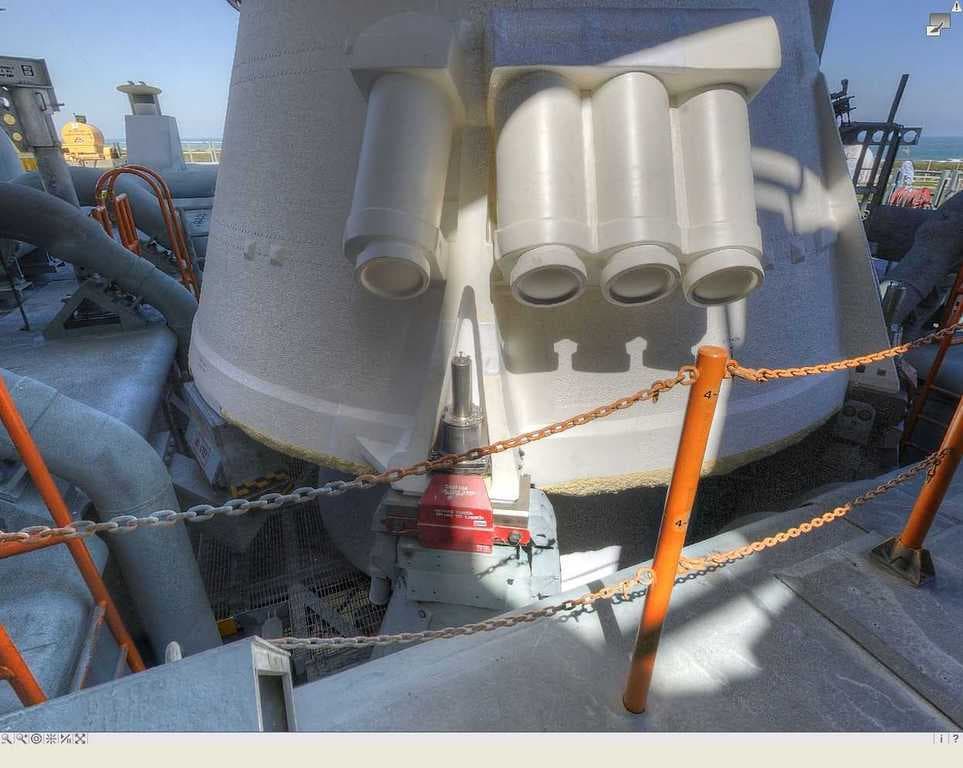
One day after a long time I first came across this picture, where one can see this interface assembly group undisguised. 

Source: NASA
On it one can see a slanting box with several contacts, which is an Umbilical interface to the Booster, as I found out from a longstanding Pad guy in NSF forum (padrat). ![]()
But I still wasn’t satisfied with that, ![]() kept looking and actually found a nasatech panorama on which one can see this interface in contact with the Aft Skirt of the booster.
kept looking and actually found a nasatech panorama on which one can see this interface in contact with the Aft Skirt of the booster. ![]()
3D-rotatable view of this area at nasatech
And at this salvaged burned-out booster one can recognize this interface too, and in the zoom even a bit better.

Source: wordpress.com
And if that’s not enough as an explanation, one can look at this image and read the labeling of the interface. ![]()

Source: Library of Congress
So much to this small detail for anyone curious. 
![]()
2 Likes
Bravo another mystery solved – I guess it had to be something electrical to need protection. I’m more used to seeing the old Saturn V launch footage, where the umbilicals were yanked out much higher up the side of the boosters ![]()
1 Like
That was pretty tricky to find out, ![]() but seek and you shall find.
but seek and you shall find. ![]()
![]()
Hi friends,
before I have started with the dimensioning of the parts for the outlet from Ø 3,2 mm to Ø 2,0 mm, I have looked some of the details a little bit closer.
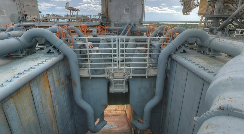
As one can see in this Street-view image, the bends of the outlets are about at the same height,

Source: NASA Street View
and the geometry of the tube turns seem to be about the same.
3D-rotatable view of this area at nasatech
Source: nasatech.net
Here you can walk around the whole SSWS pipe system and look all details closer. ![]()
Walk around the SSWS
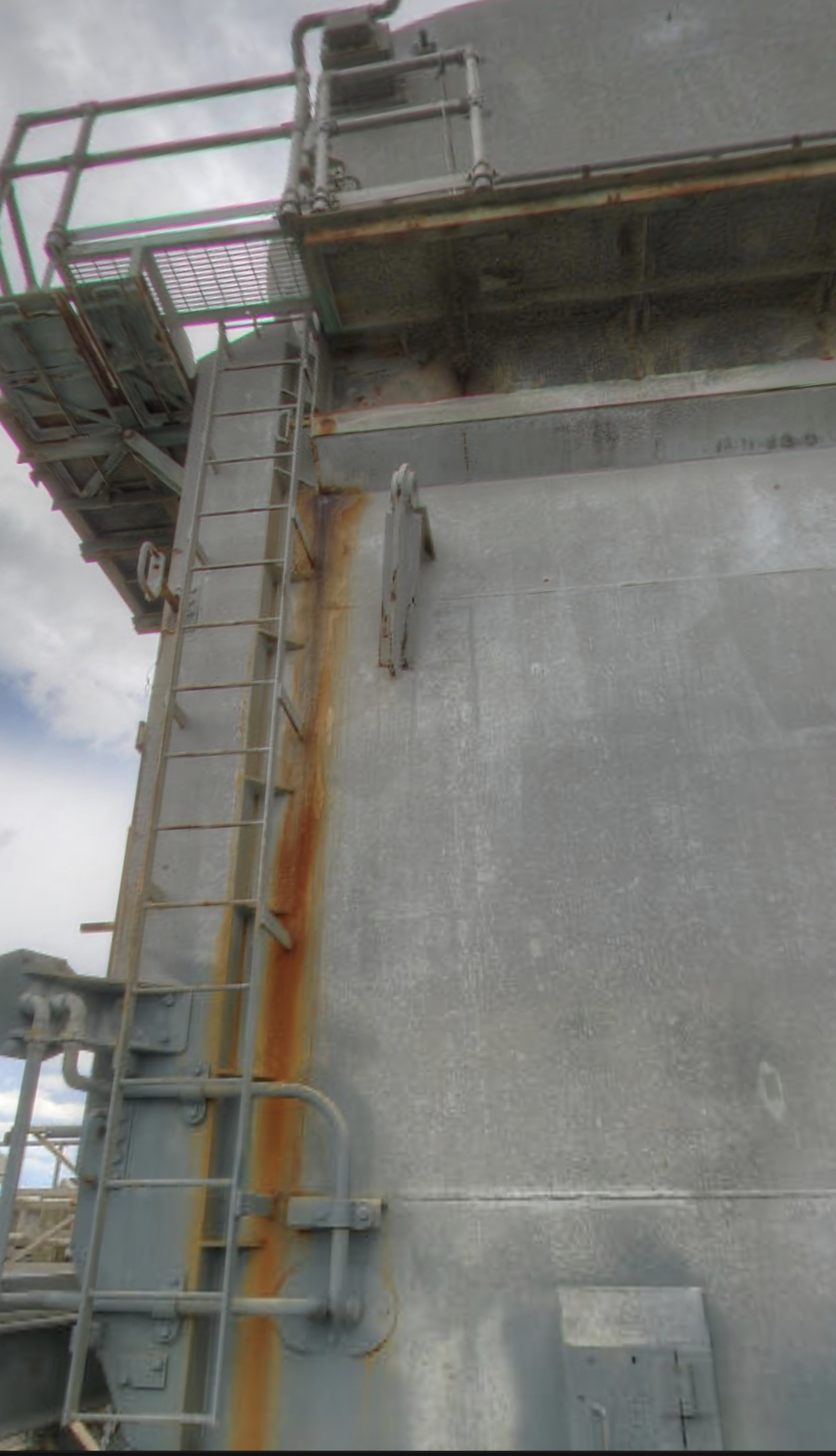
As one can see in this panorama, the transition region to the tapering lies approximately over the top of the triangular pipe support, and the vertical 12’’ outlet is scratching even at the SRB-Blast Shield.

Source: nasatech.net
And since this outlet is directly running to the shaft wall downwardly, would this 18’’ tube turn actually be somewhat narrower or shorter than that of the outlet behind the SRB support with no taper. Accordingly, the pipe supports should be about the same size, I guess.
And this outlet I have now composed of two parts. The shape of the upper bow (Ø 3,2 mm) is identical to that of the previous outlets and was cut off at the point above the triangular support. And then the angled part of the taper was attached (Ø 2,0 mm), whose transition still will be modeled with Apoxie Sculpt.
The image shows also the first attempt to indicate the outflow opening at the end of the pipe.


Source: nasatech.net
For this I have drilled out the 2 mm rod below with Ø 1,6 mm and removed one half of the “tube”. The resulting opening becomes still beveled and closed downwards with a small disc. And I mean that one can definitely accept it, right? ![]()
And this is now the test fitting of the tapered outlet at the ring line. But as one can see, unfortunately, does not fit properly so, which indeed would be too good. 

The upper 18’’ bow protrudes too far inwards, whereby the support does not fit under the 12’’ outlet, which also is not snug enough on the shaft wall. ![]()
That’s why I have to shorten the inside of the bend a little bit, whereby the outlet is coming closer to the shaft wall. Thereby the support also should fit better under the tapered part, I hope at least. ![]()
So I have further experimented and both the 18’’ bow as well the 12’’ outlet slightly shortened.
And this is the preliminary result. The outlet has thereby indeed moved a bit closer to the shaft wall,

but the bend protrudes still too far inwards, whereby the clearance for the support is still not enough.

Therefore, the bow must be estimated shortened by 1 mm, then it possibly could fit better. ![]()
Step by step one gets closer …
Here is the result after the shortening of the bow.

And lo and behold, now the support fits better. 
At the front outlet this support inevitably is missing now, whereby this is not fixed properly and logically sagged down too much.

Thanks for watching and bye for now.
![]()
4 Likes
Hello everybody,
if one looks at this 12’’ outlet more closely, one can see that it is still too much rounded at the kink, ![]()

which is why I have this pronounced even stronger, as can be seen right in the image.

And from these outlets I need a total of six pieces that I need to scratch now.
Since the 18’’ bows of these tapered outlets but are slightly narrower than those of the other four 18’’ outlets without taper, I had to create a new Balsa template for bending. ![]()


For further handling, it was skillful, initially to file the rounding at the left end of the bow and only then to remove the right end of the bow. ![]()

How now the test fitting in the next image shows, the new bow is but still a bit too long and still needs to be shortened somewhat, so that the outlet comes closer to the shaft wall. ![]()

And then I have tried to also represent the outflow opening opened at the 18’’ outlets, whereto I drilled out the end with Ø 2,5 mm and sanded a bit at the inside.

Then I have heated the opening and pressed together in the sliding caliper.

And this opening really appeals to me actually completely well,

especially as it looks more realistic than the first attempt. ![]()

Maybe I’ll find even a slightly larger drill to reduce the wall thickness a bit more without having to smooth the opening yet. ![]()
![]()
2 Likes
Attention to detail at an unbelievable level… amazing
Thanks John for looking in on me again. ![]()
The SSWS is the most time consuming chapter and is a real challenge for a scratch builder like me. I can’t let go until I’m really satisfied with a certain solution. ![]()
The greatest difficulty here is the reproducible bending of the multiple-bend pipelines. ![]()
That’s why everything takes a little longer and requires a lot of patience, but what I have fortunately.
![]()
2 Likes
I have not tried to bend pipes and I have read many modelers have problem with such skills as it’s truly an art to bend a pipe and keep its shape true. Looks like you have this art down as the results are phenomenal ![]()
Thanks Mike for your nice compliments. ![]()
In reality, the SSWS are pipes, but to be correct, I have to say that I’ve bent round rods and not tubes, since bending pipes can be a bit trickier to do, what I haven’t tried it yet. ![]()
![]()
Hello everybody,
after the first training, I have now begun to scratch the six outlets with the taper from 18’’ to 12’', which consist of two parts. ![]()
Thereto at first I have bent the 18’’ bows with my new Balsa template, and then the simple angles of the 12’’ outlets. The shortening of the bows happened initially based on my sketch, but the comparison of the bows showed slight differences in width. ![]()

So I had to be little more exactly when shortening the bows, wherefore this upper stop was helpful. So the position of the bow is clearly fixed, and the shortening always happened in the same place, which has thus delivered same lengths.

Thereby the 12’’ outlets could be precisely measured and shortened, which in turn shows how important a defined stop is. ![]()

And finally, still the test arrangement of this modified outlet, here still in the wrong place in front of the SRB support, but not too disruptive in this case. But it is just clearer than on the back of the support. ![]()

And so now to the outlet opening at the bottom that I had already tried.

The 2 mm (12’') rod I have drilled below with Ø 1,5 mm, have cut the opening and beveled, and then glued a disc with Ø 2,5 mm as a final deflector. And then there’s still this little protective plate, which I’ve rounded from 0,1 mm Styrene.

And then finally it looks like this,


and would be the outlet at this point, whereby the outlet opening is obscured however here.

Thanks for watching. ![]()
![]()
1 Like
Another neat update ![]()
Thanks John for staying tuned. ![]()
![]()
Hello friends,
today we broke the sound barrier of 1 Million views in our German Raumcon forum. ![]()

If that is not a reason to celebrate. 
Cheers! ![]()
![]()
2 Likes
Well done on that milestone … impressive numbers indeed.
Wow, 1 million views. You are a celebrity builder my friend. Keep it up!
Thanks John and Mike for your good wishes. ![]()
Stay tuned guys, the show will be going on. ![]()
![]()