Space Shuttle Launch Complex 39A with Challenger STS-6 (1:144)

Hi everyone,

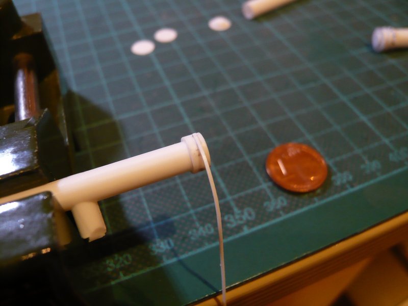
there is still the supplement to the nozzle pipe on LH2 TSM, which now also waiting for the final assembly and mounting to the 24’’ ring line, which will follow soon.

And so I would then also have crossed through the maze of SSWS pipes.
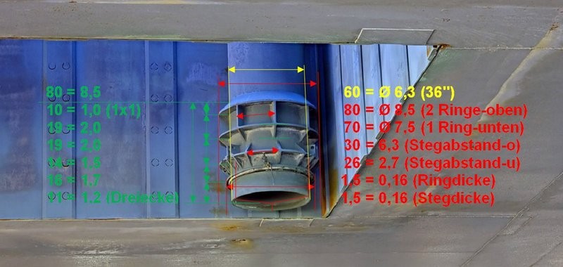
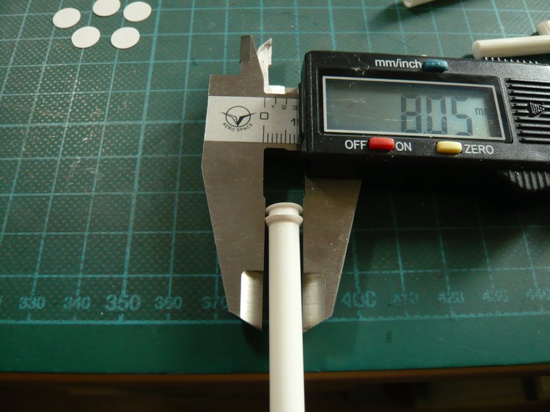
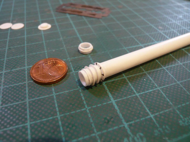
After lately the pipe diameters became smaller from 24’‘-18’‘-16’‘-12’‘- 9’’ down to 6’', it now once again goes back to the thickest 36’’ pipes (Ø 6,3 mm), through which both ring lines being supplied with water.

The connecting pieces of the feed pipes in the corners of the SRB Chambers I had mounted already during bending of the ring lines.

3D-rotatable view of this area at nasatech

Source: nasatech.net

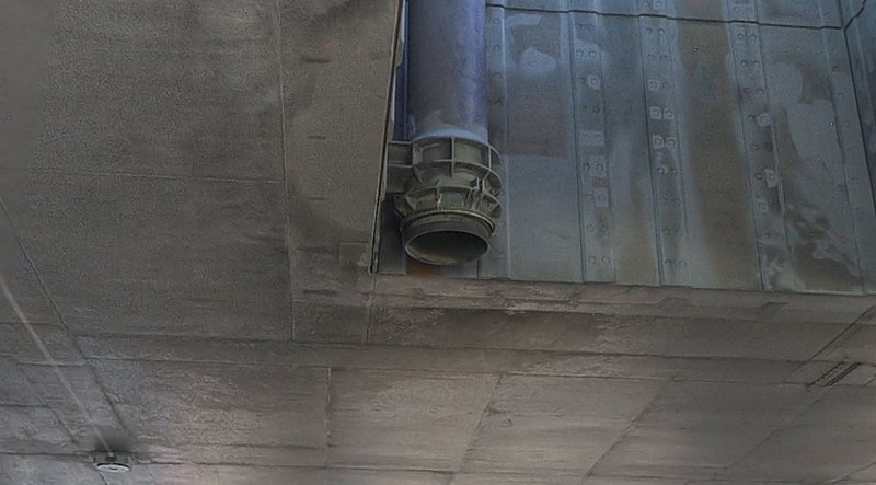
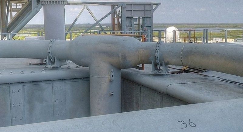
Here is another great panorama view from under the MLP.

3D-rotatable view of this area at nasatech

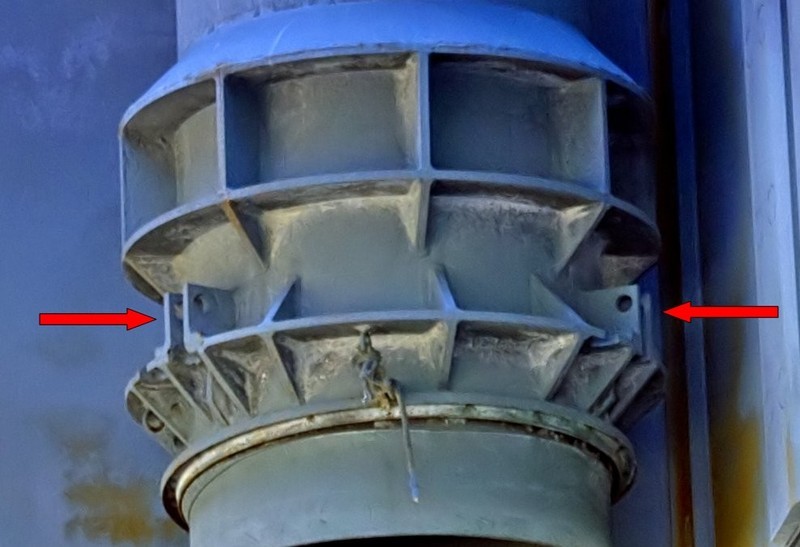
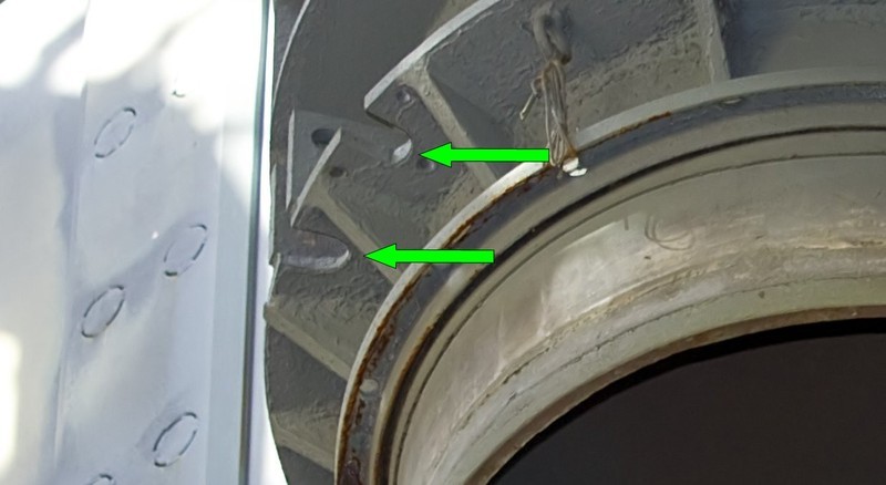
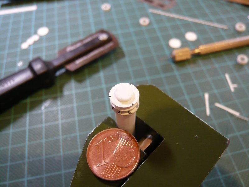
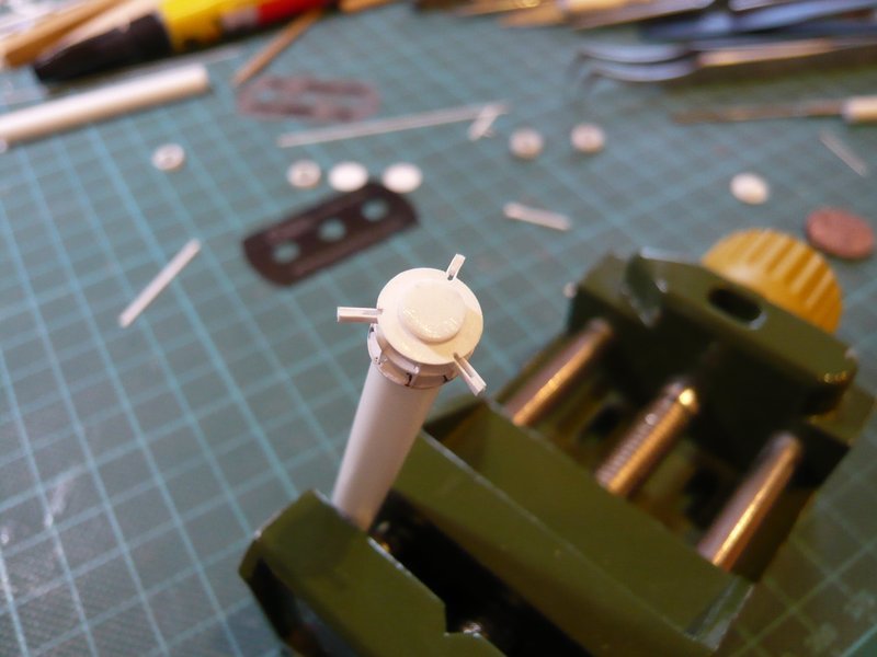
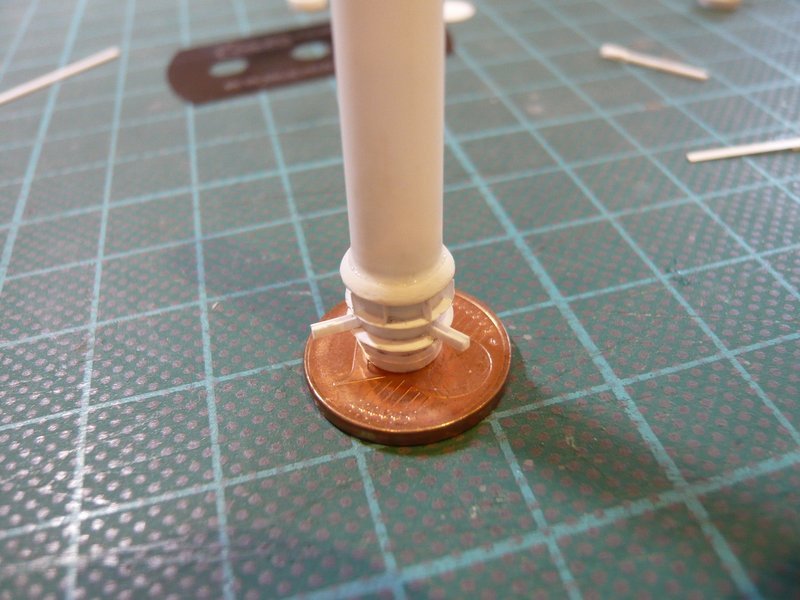
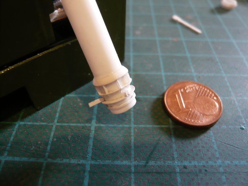
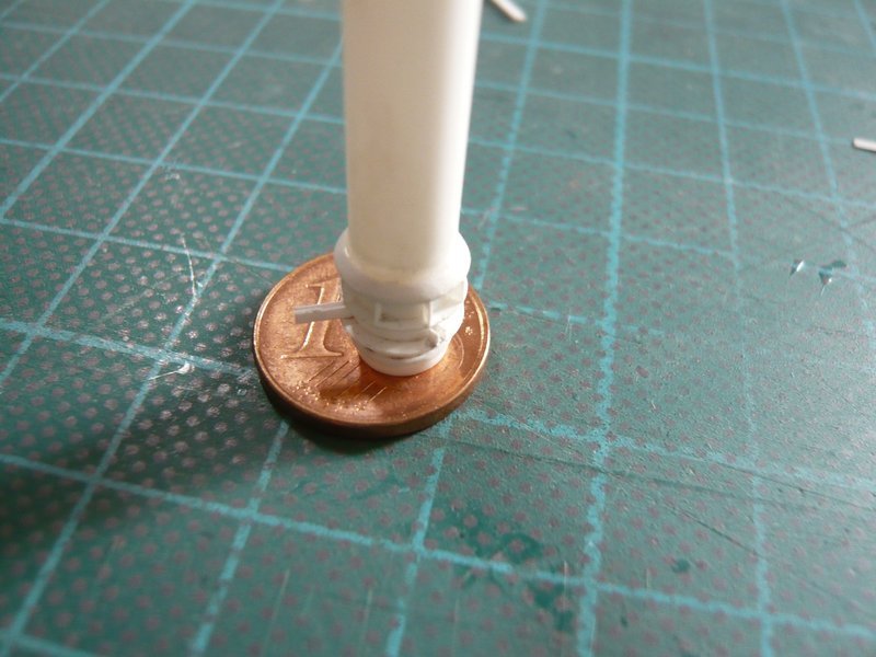
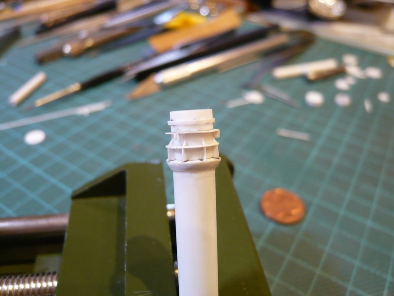
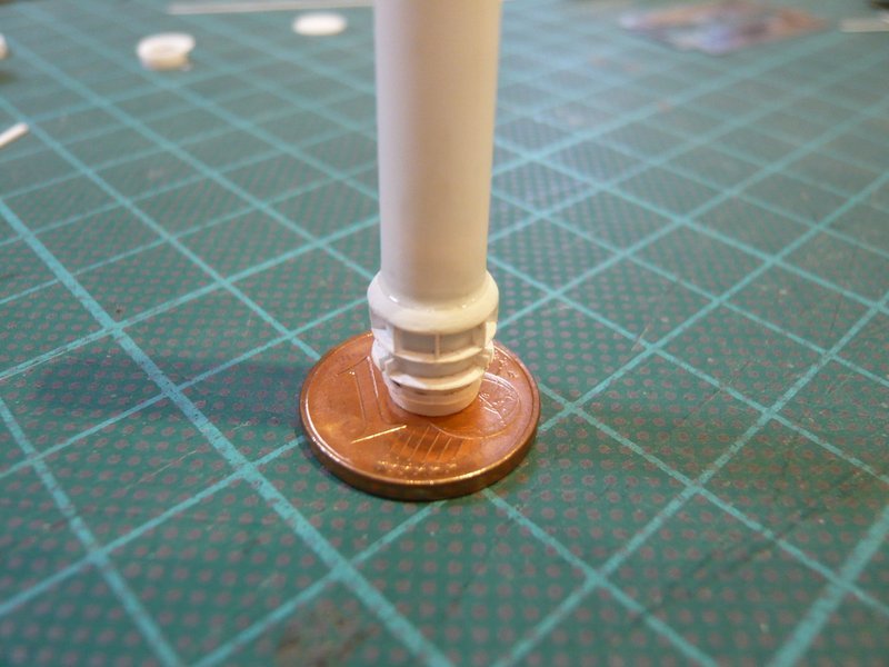
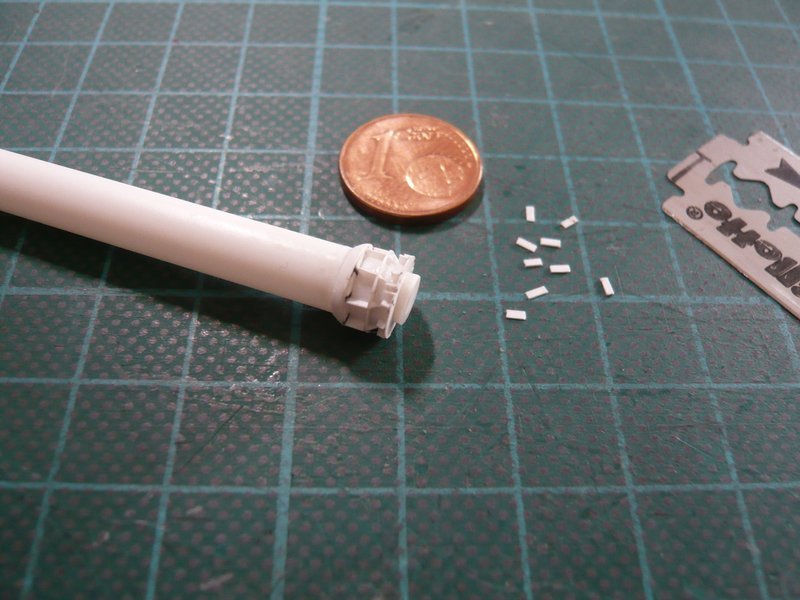
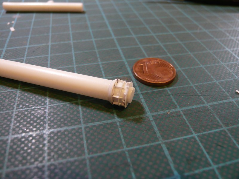
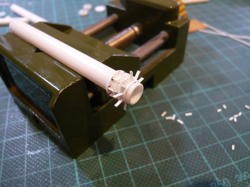
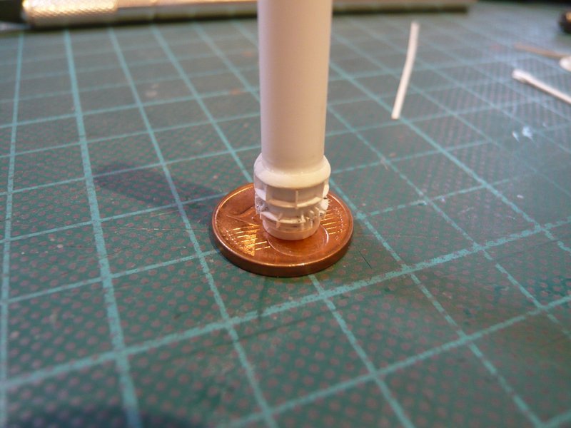
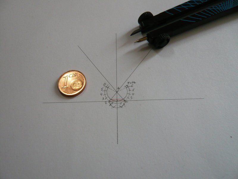
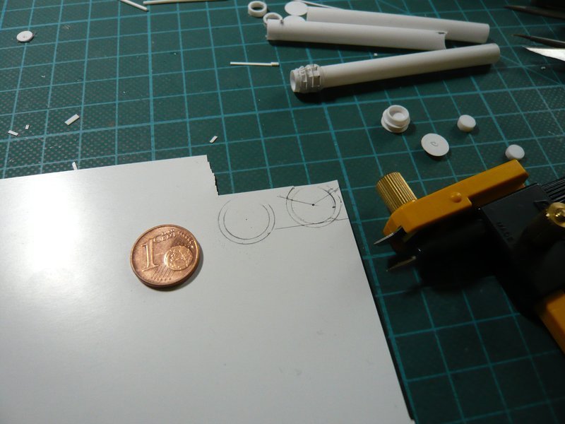
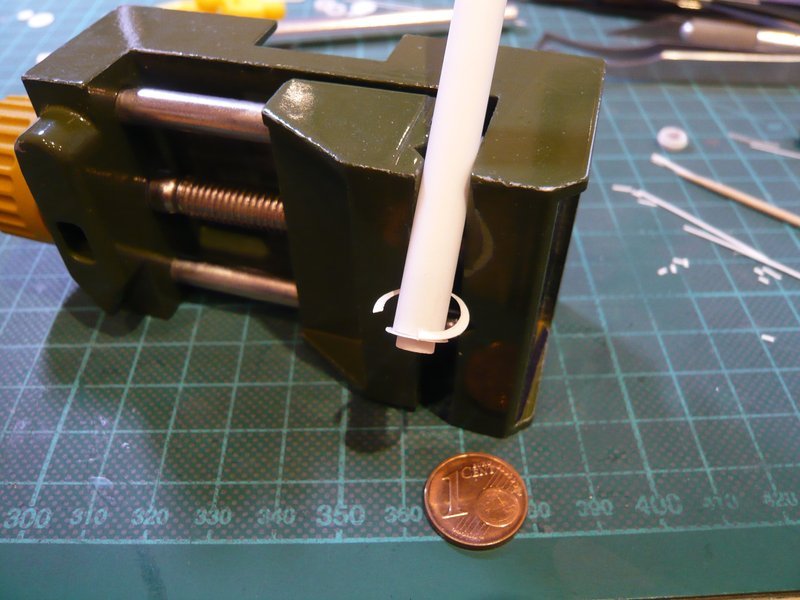
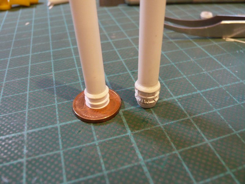
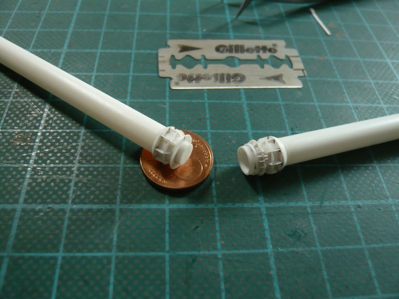
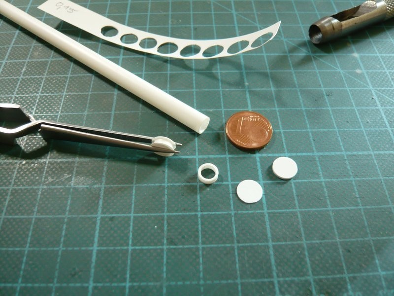
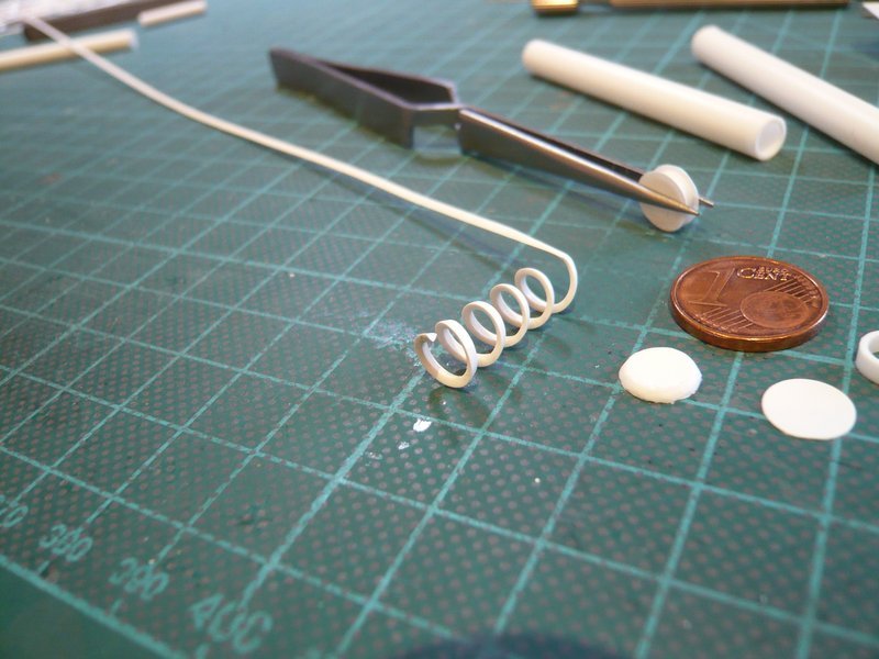
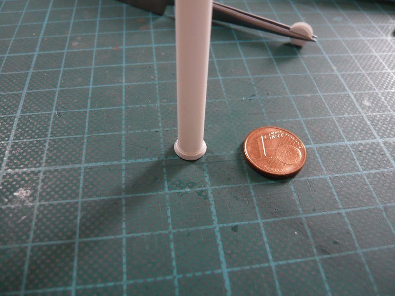
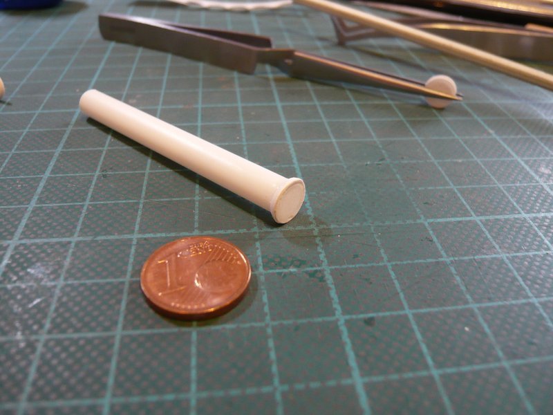
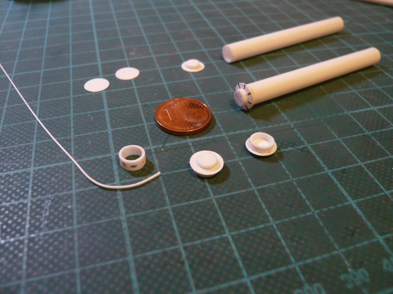
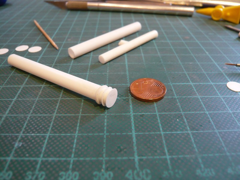
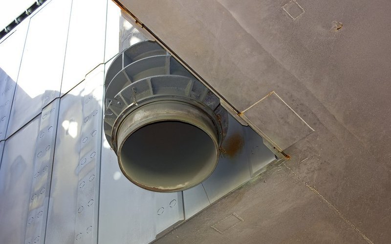
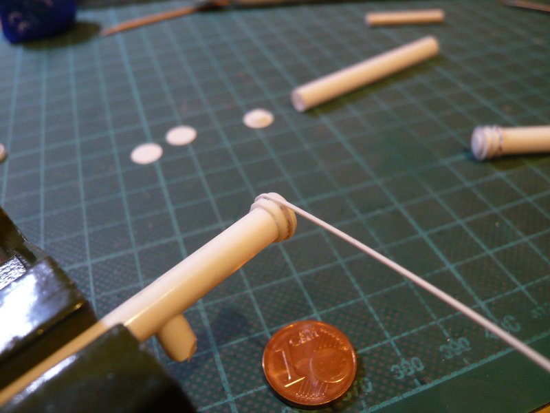
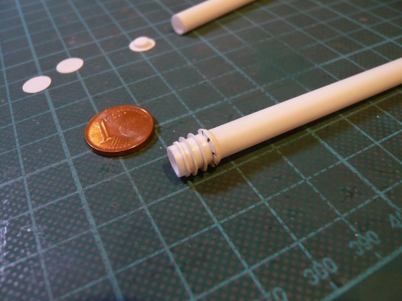
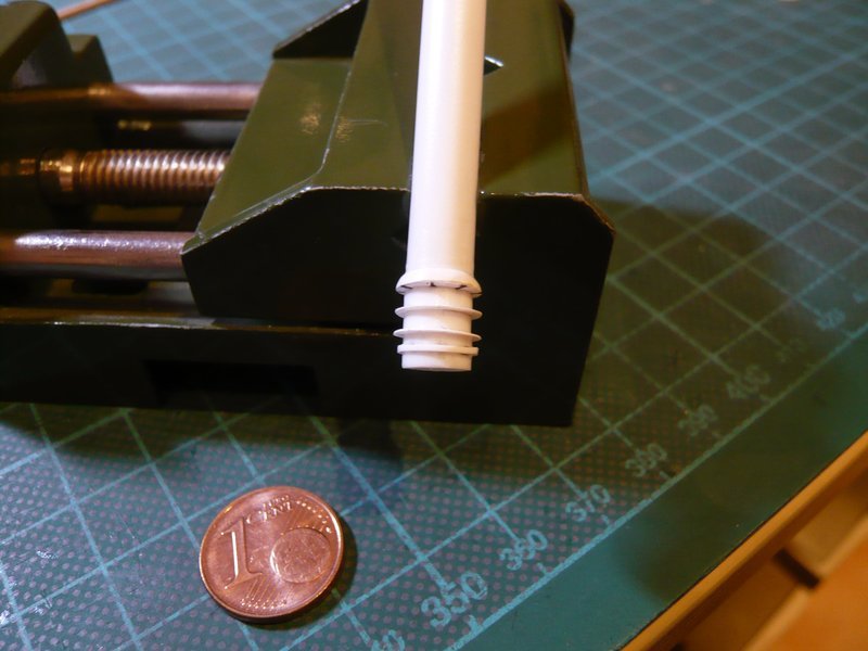
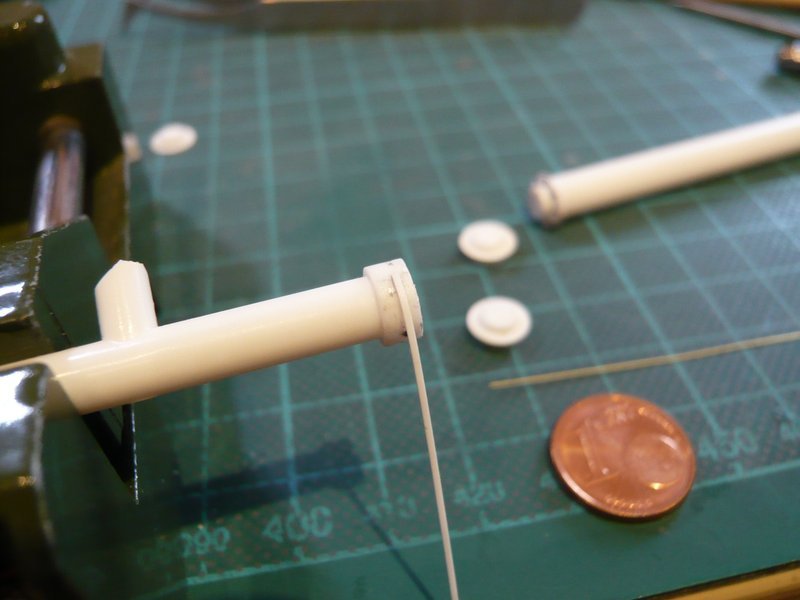
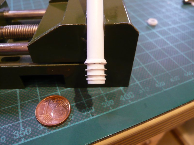
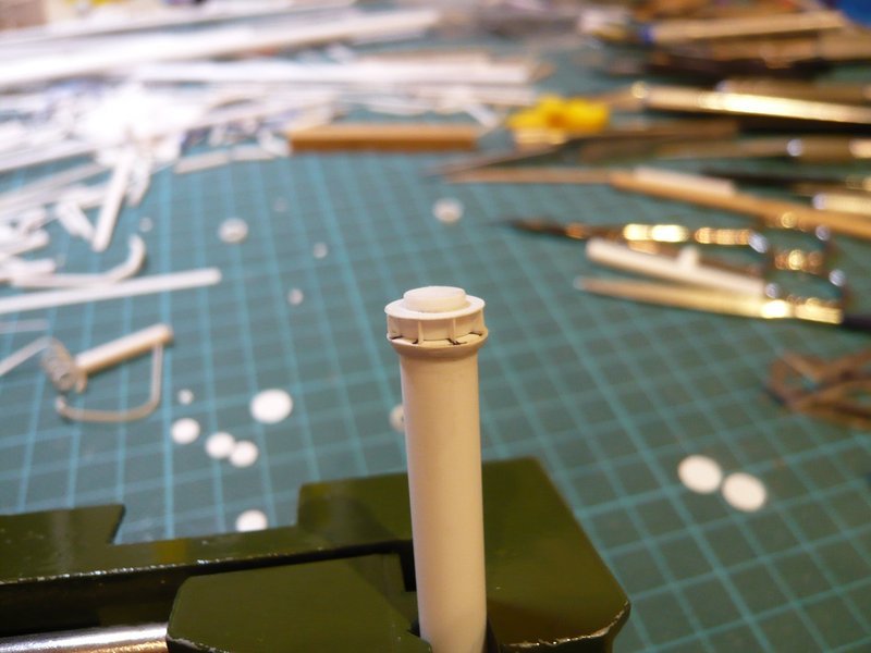
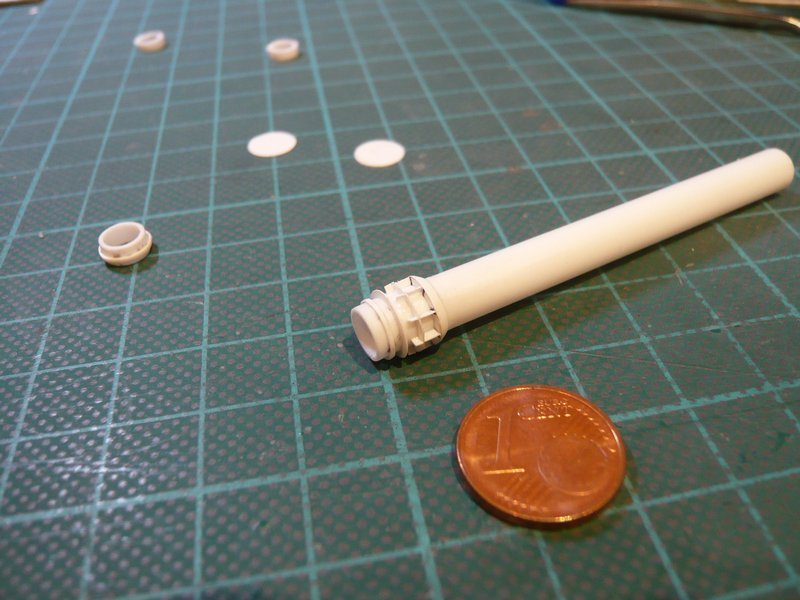
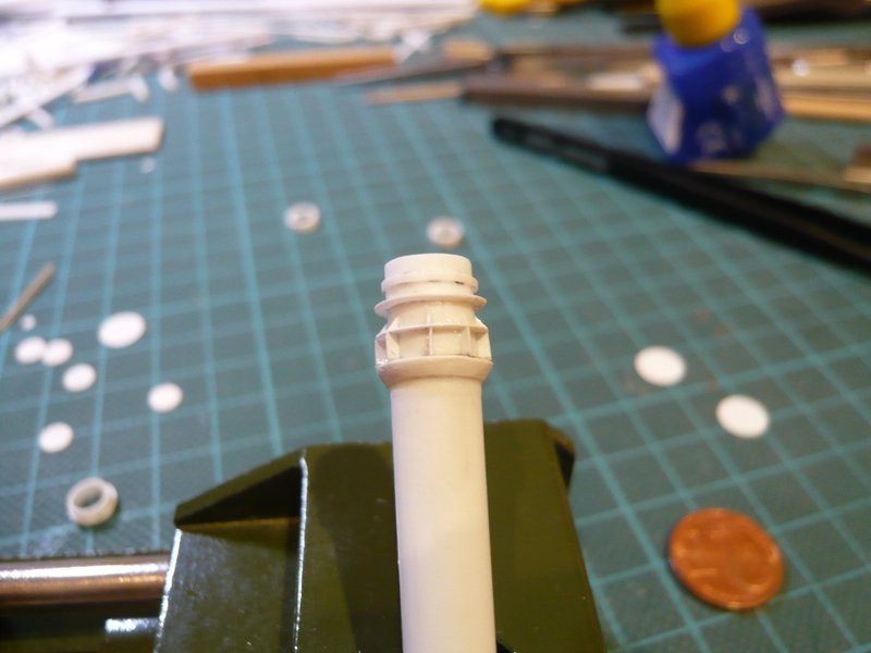
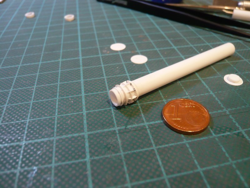
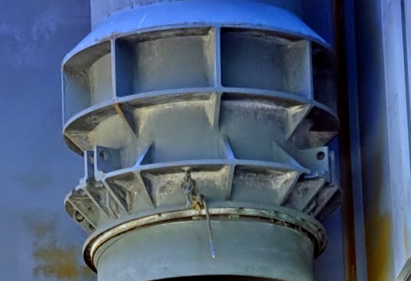
And now it comes to the lower end of the tube with the connecting piece, for whose items I have again estimated their dimensions.


Source: Troy McClellan

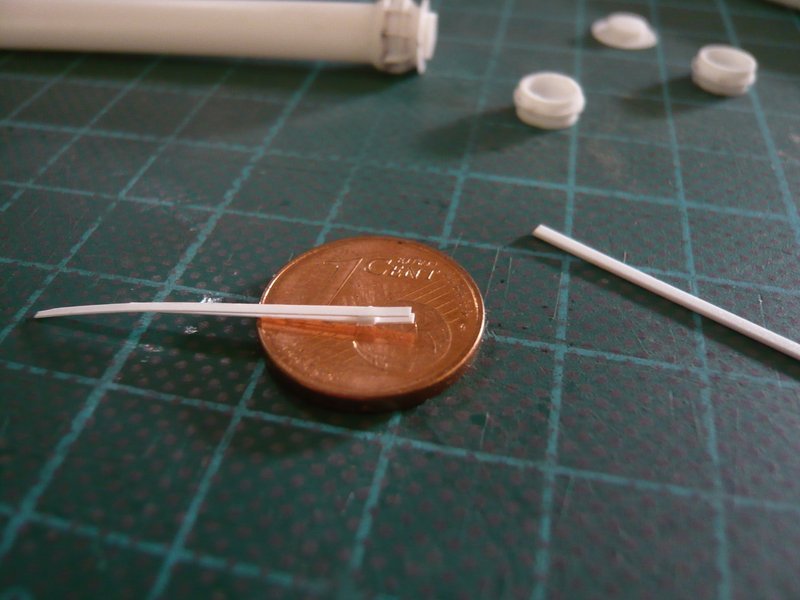
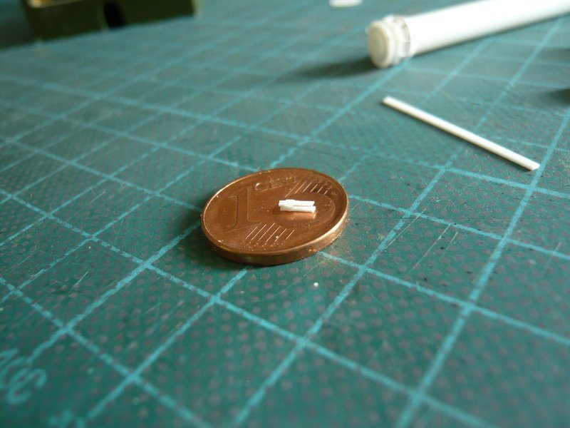
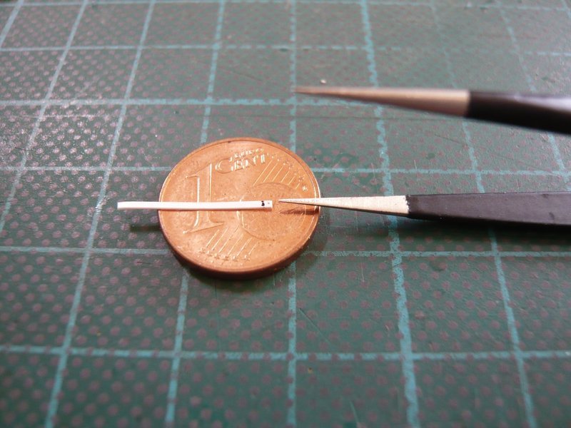
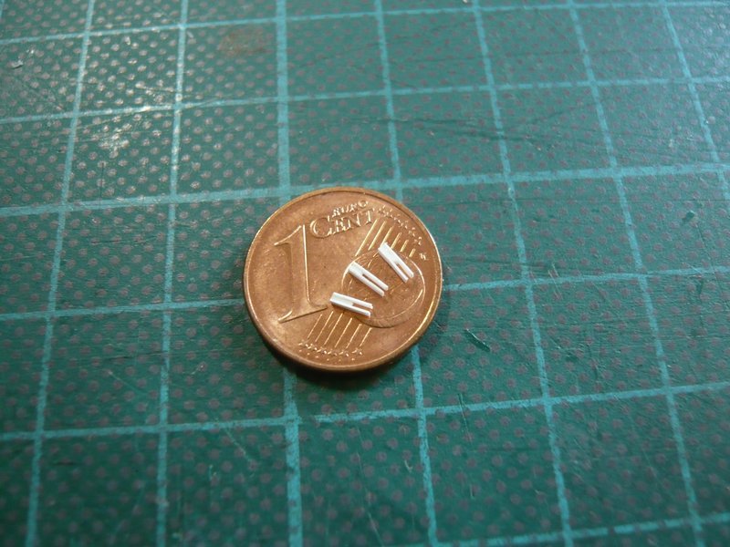
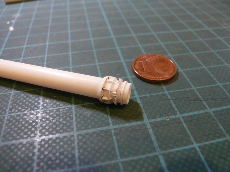
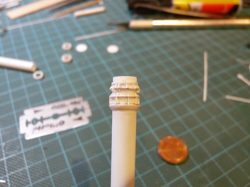
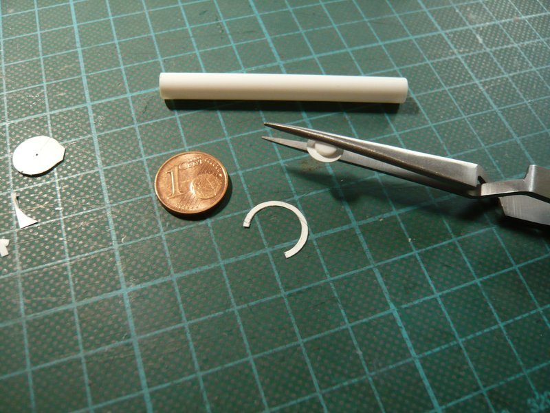
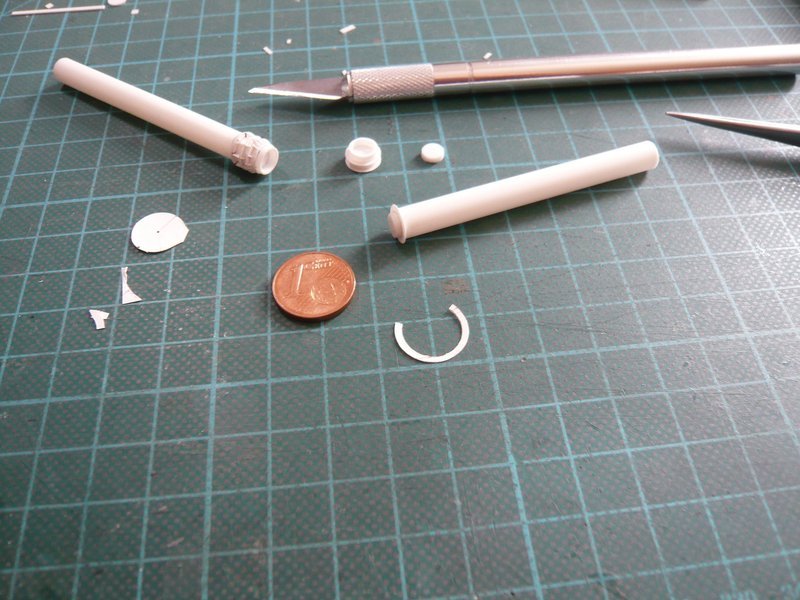
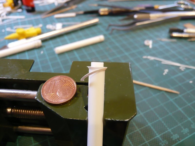
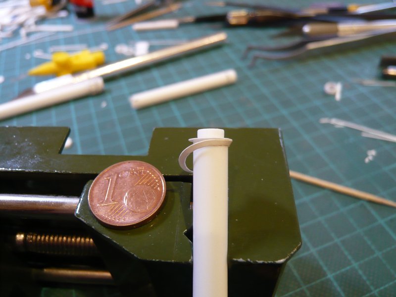
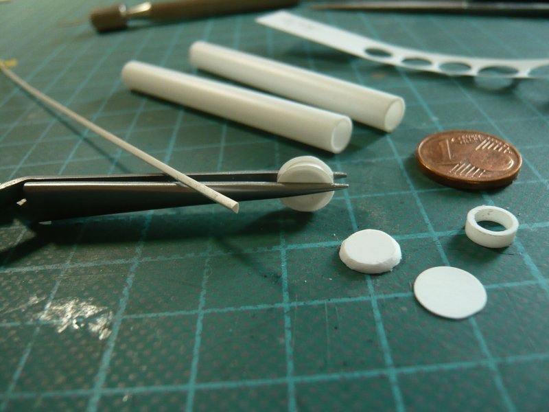
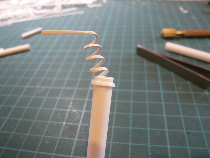
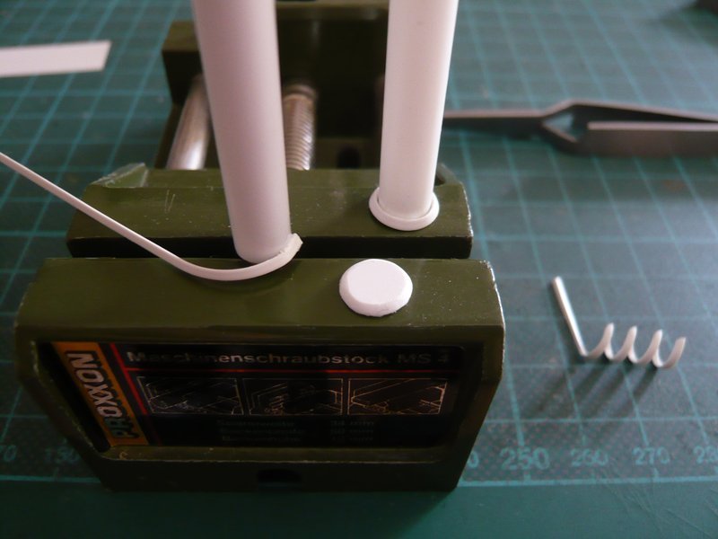
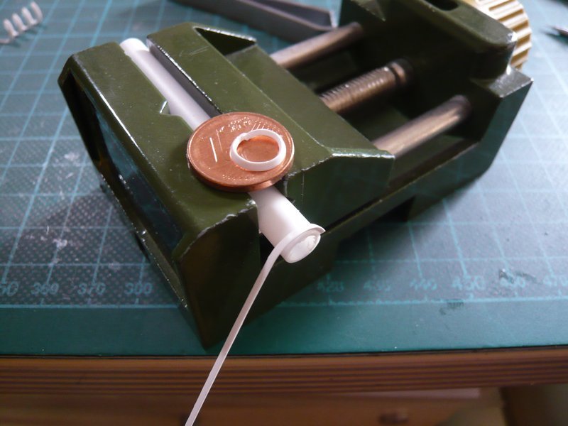
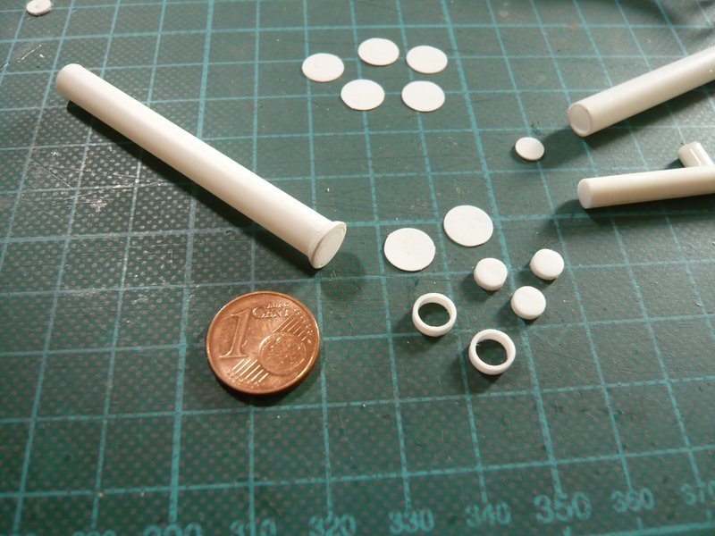
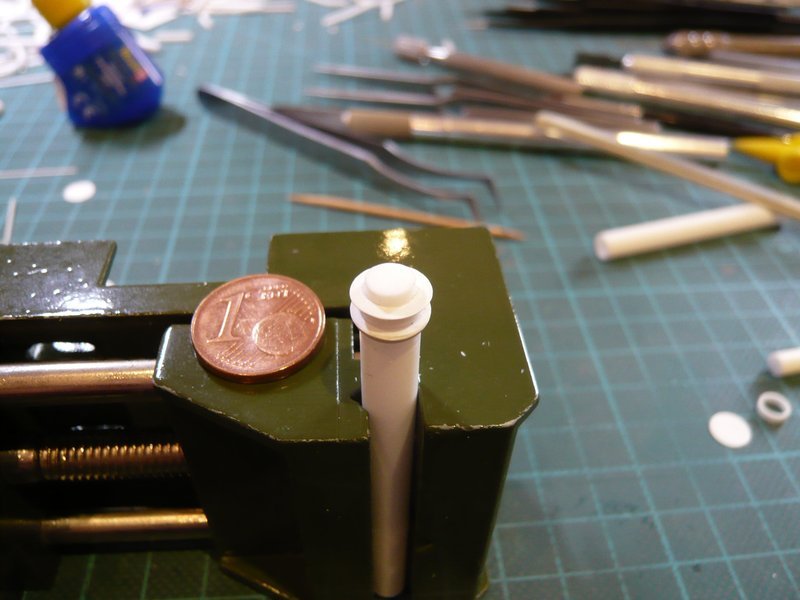
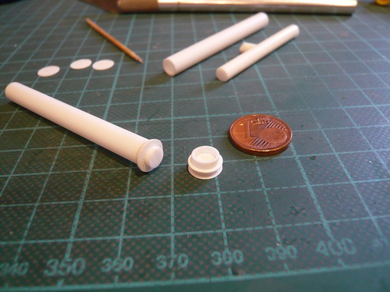
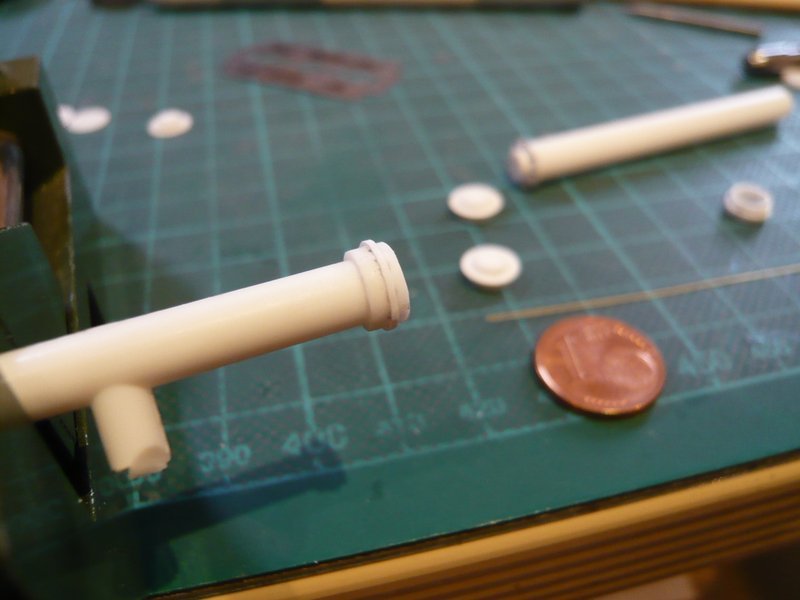
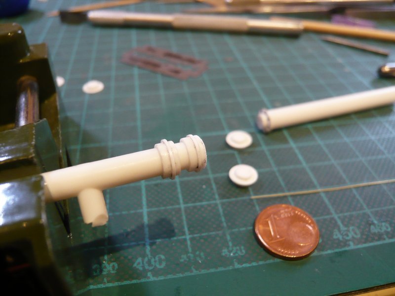
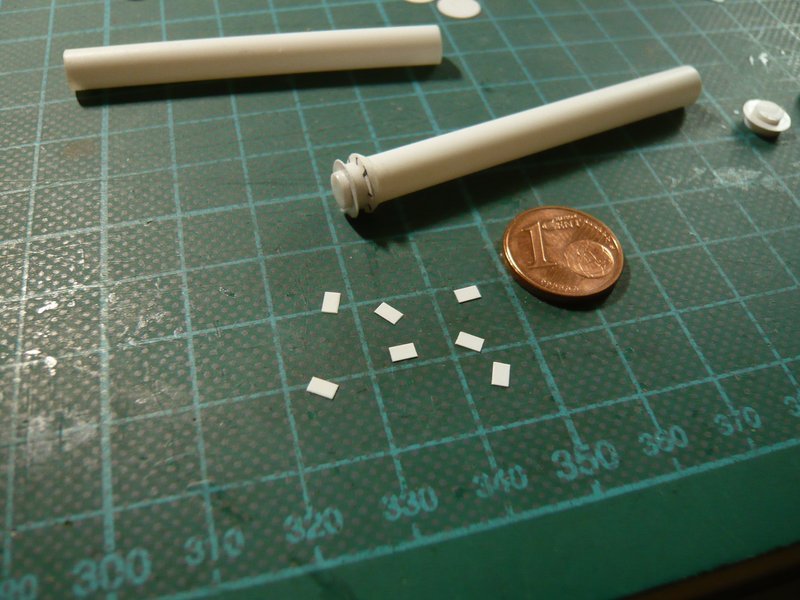
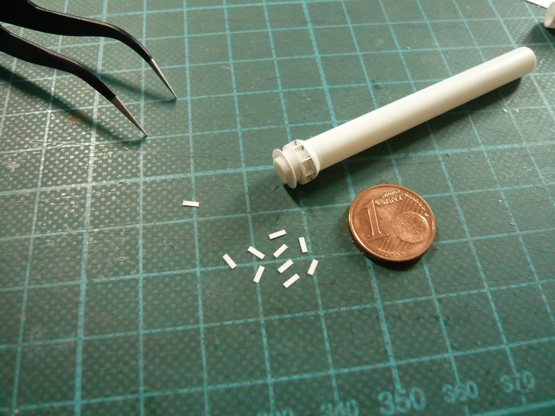
For the construction of this connecting piece I have imagined that I could cut the 6,3 mm tube into short rings, which are subdivide by punched plastic discs (0,15 mm) and finally are glued together.

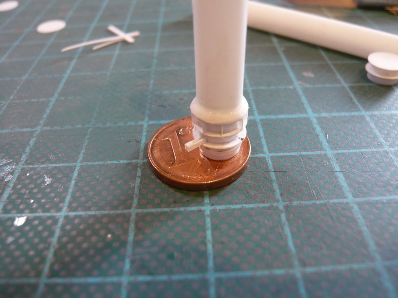
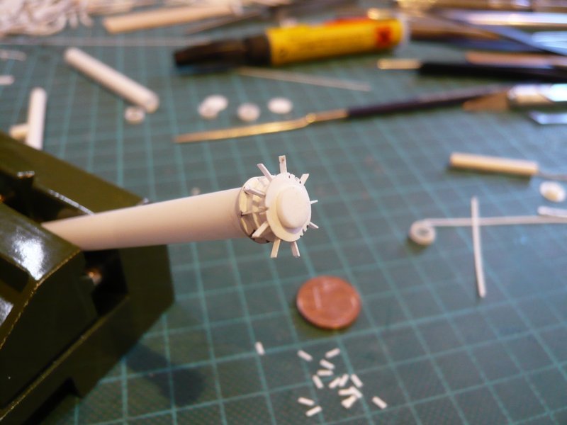
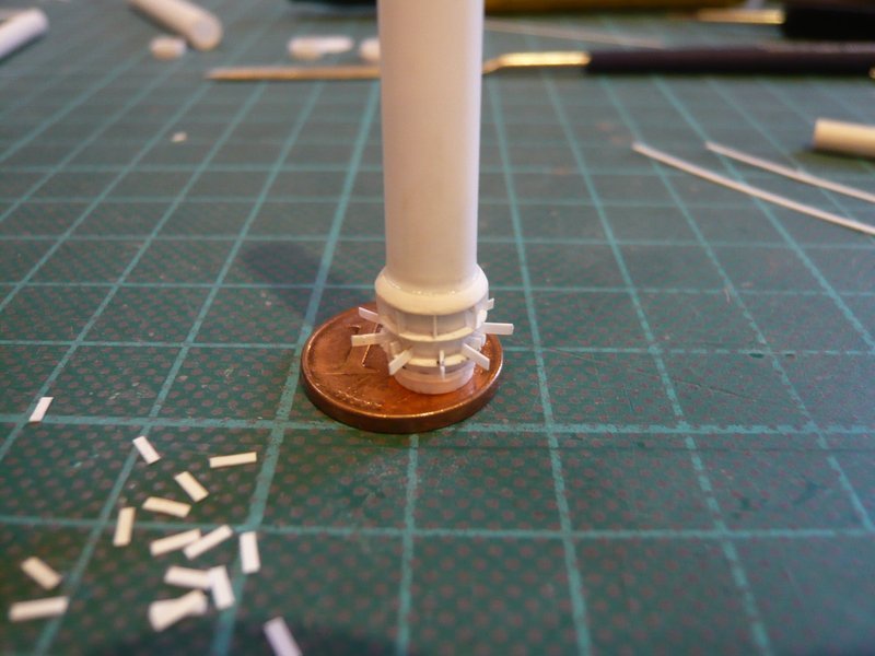
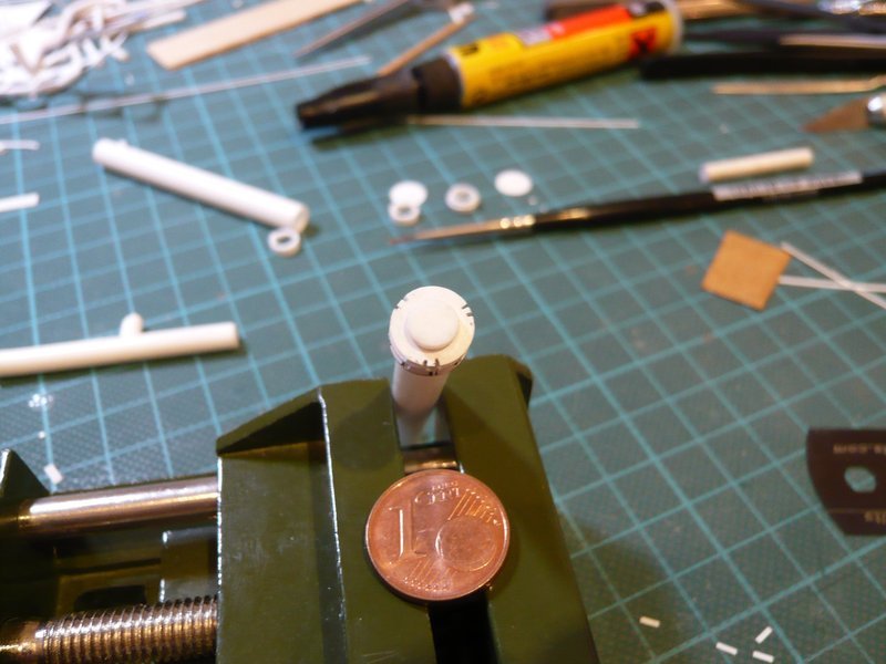
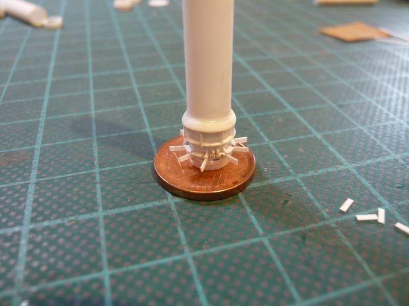
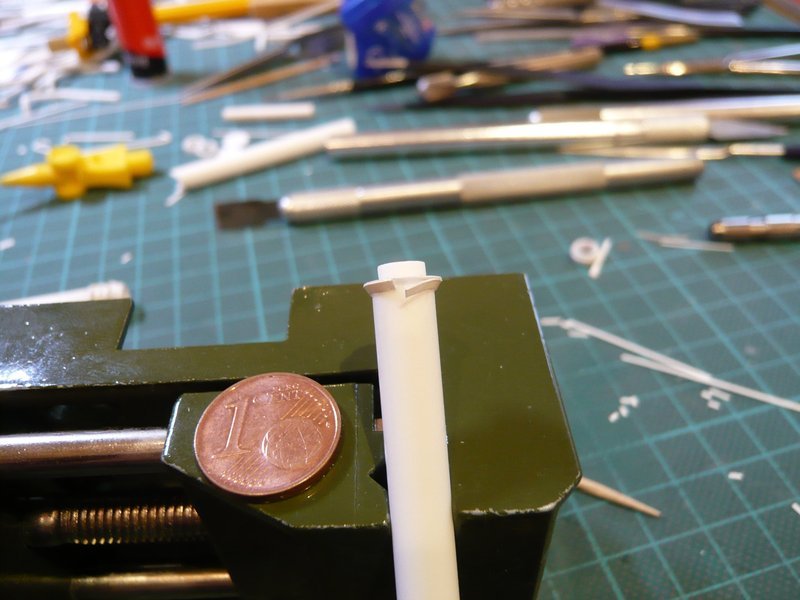
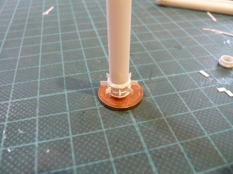
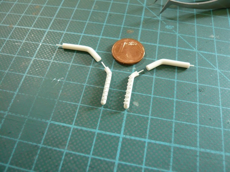
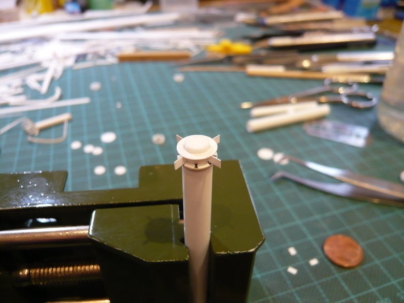
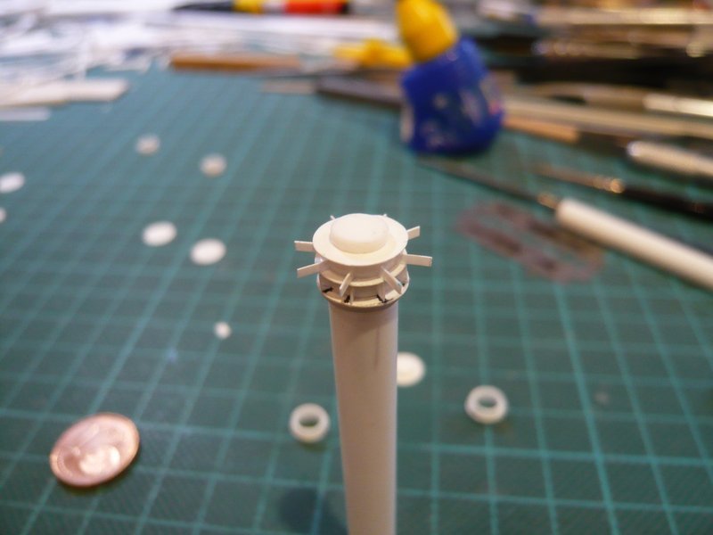
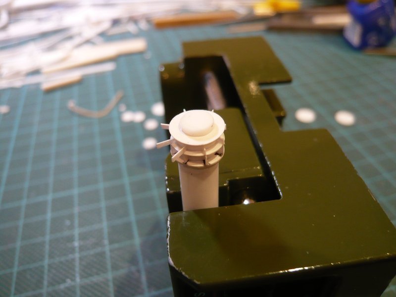
The more difficult part of the exercise subsequently follows, when these tiny stiffening ribs and corners must be glued all-around, for which I already have an idea, but what could become quite a tricky fumbling.

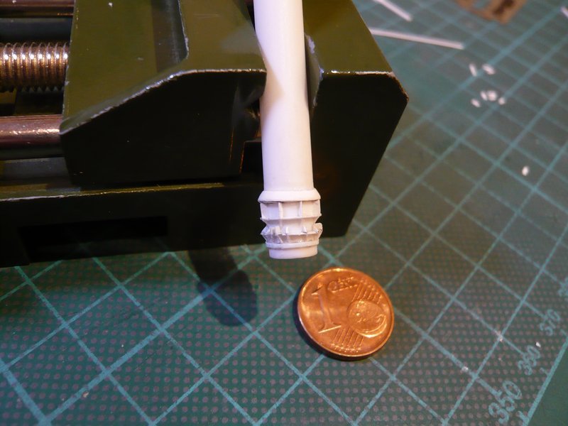
As far as for today.

1 Like

When I look at the detail you do, and the time these initial build ups take, then if you have to correct something…the sheer effort leaves me lost for words … I go crazy putting a set of indi track links together…:see_no_evil:

Thanks and keep cool, John.

For me it is the purest déjà vu feeling …

If I have to take a closer look at these details again after many years in order to post it for you, I am often speechless too and amazed at how I did it that time …

And if I don’t get a detail right the first time, I try to do it better the second or third time until I’m satisfied, saying to myself: It’s now or never!

1 Like

Kudos to you :+1:

Thanks John!

Learned again something, my Samsung translator says: Hats off!

BTW, you seem to be the lonely and only one here with an opinion.

But one is better than none!

1 Like

Whoa, whoa, hold them horses…I’m here!

1 Like

Well roared, Lion!

Glad you got out of the saddle again, my friend. Wanted to start a missing persons report already.

2 Likes

Hello friends,

before the tiny stiffening ribs and corners get their turn, the subdivided construction of the connecting piece must first be put into practice what I first have tried, whereby I proceeded from top to bottom.

This starts up on top with this conical ring (truncated cone), about which I’ve been thinking.

One possibility would be to file off a circumferential 45° bevel to a 1 mm thick slice (Ø 8,0 mm), what is tedious and not easy if it should become perfectly round, as one can see.

Then one could also imagine a ring of triangular profile (60 °), as can be seen on the tweezers. That is not from Evergreen, but in an architecture shop I have found and was very happy.

But already at the hot bending of the rings proved the profile to be quite stubbornly because it has aligned to the wood core, as it wanted,

and has also still twisted itself.

Thus, it could not so nice and smoothly be attached to the 36’’ feed pipe (Ø 6,3 mm) as I would have liked. As can be seen, namely a gap emerged at the top, what I do not like and still has to be filled somehow. But then one could also mould the bevel with Apoxie Sculpt.

So I wanted to try something else and have glued a slightly pre-bent triangular strips all around with CA.

Although this has worked a little bit better than before, but a smaller gap could not be avoided altogether.

But with the result I first times contented myself in order to test the further construction. But I definitively did not wanted to glue together the rings and discs in order to make even possibly corrections of segment heights. That’s why I have cut small 1 mm base plates of a sprue, which correspond to the inner diameter of the rings.

These plates should serve as a base, on which then the rings are placed loosely without glue.

Then followed the stepwise construction of the connecting piece with the parts, whereby one has to pay attention on a central alignment of the slices and rings.

On the lower tubular segment of the connecting piece sits a double-profile ring, as can be seen in this picture.


Source: Troy McClellan

In order to scratch this ring simplified, I glued an Evergreen strip (0,4 mm x 0,5 mm) around the lower tubular segment.

Then I have put together all the segments, whereby the connecting piece slowly takes its shape.

However the lower ring appears a little too massive, maybe a strip 0,25 mm x 0,5 mm would look something more pleasing from what I could still try, 
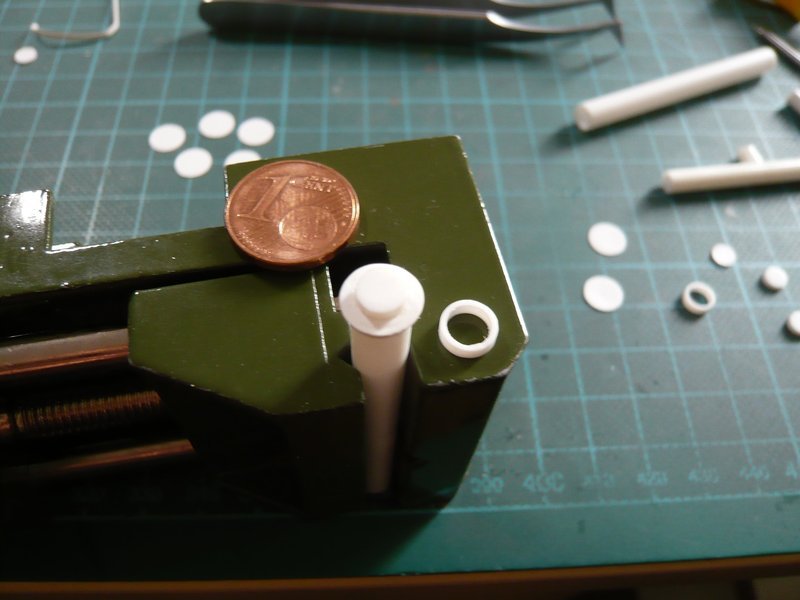
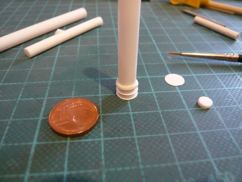
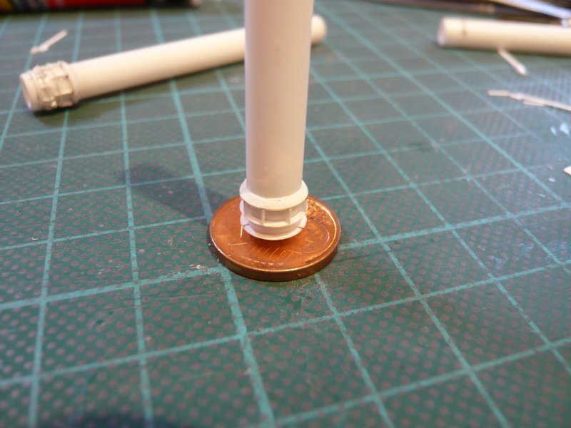
especially because the connecting piece still can be disassembled.

Now then are still missing the stiffening ribs and corners, for what I’ve come up with a special trick again, which I will present next time.

Therefore stay tuned.

2 Likes

Let’s go guys,

as already indicated, the lower ring of the connecting piece I have still slimmed down a bit and by using a thinner strip of 0,25 mm x 0,5 mm.

And in a direct comparison of both rings the optic of the new ring (right) looks something more pleasing, I think so,

but that is as always a matter of taste.

And now followed the upper eight stiffening ribs, for what I have cut short Styrene strips (0,15 mm), which are a little longer in order to assemble and glue easier,

which I have again done with MEK.

But do not worry, I’m not on the wrong path, this should not become a turbine rotor.

And now only the protruding ends had to be carefully cut off with a razor blade from top to bottom,

which has pretty well worked.

However I fear, that the tiny stiffening triangles certainly shall become much more complicated and stressful.

3 Likes

Amazing work continues. Yes the lower smaller ribs are going to test your patience & there are a lot of them. Maybe you could glue rectangular pieces in place, and then cut them at a 45° (?) diagonal angle with your sharpest blade, instead of cutting triangles?

2 Likes

Yep Tim, that was exactly my plan at the time, true to my successfully implemented idea with the overhangs, and then to cut them with the narrowest blade, so again with the razor blade.

1 Like

Hello folks,

to be frightened is not an option, and so I have got down to work, whereby the manufacture of the triangular stiffening ribs happened according to the same recipe for success.

First, I have cut 0,8 mm wide strips of 0,15 mm Styrene and separated from these then 3 mm long sections.

But now came the gluing, and I first tried with the normal Revell glue. But due to the minimal contact zones (0,8 mm x 1 mm) it is quite problematic to establish a sufficiently strong connection. For the fixation of the strips it was initially sufficient, but if they would survive the reducing of the overhangs, I was not sure.

Therefore I wanted to stabilize the contacts even from both sides with MEK. But that failed because the MEK dissolves the contact point too strong, whereby the strip has lost his footing and tipped over.

At the 2nd attempt I have therefore the strips initially fixed only with CA, but this is quite difficult because the correct location must be found immediately and the seat almost can not be corrected. But with a little practice and a quiet hand then I have succeeded.

And after that, the strips then could be stabilized with MEK yet again.

In this position I then first have cut off the overhangs perpendicular with the razor blade.

And then I have gently cut off the 45° bevels, which to my surprise was actually relatively easily doable.

And now I’m actually quite confident that I will be able to scratch the remaining triangular ribs on both sides of the lower disc too.

Upon closer examination one can see, that there are about twice as many ribs as on the middle disc, which are also unevenly distributed over the circumference.


Source: Troy McClellan

And then there are as a further delicacy still three pairs of rectangular ribs (0,8 mm x 1 mm) with holes (Ø 0,2 mm), which are staggered to 120°, whereupon I cannot probably renounce, or maybe yet?

Let’s see what I can do!

2 Likes

Ouch! You must have thought you were having a nightmare seeing that last image. Kinda reminds me of my own love/hate relationship with scratch-building, how much thumb-screw torture can one take before surrendering to 3D printing? :scream:

1 Like

Wow! 'Only just caught up with all this. I don’t quite know what to say; there are those of us who build kits then there’s model-makers.

Well done Manfred - a tour de force that’s for sure.

1 Like

Thanks Tim for your nice respond,
when I have seen this Connecting Pipe socket for the first time, I thought for myself,
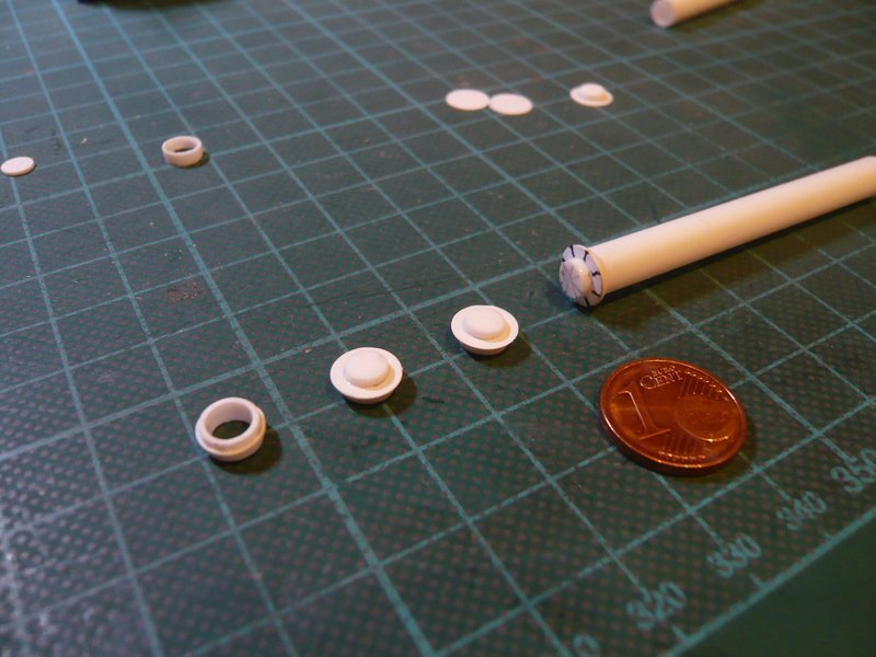
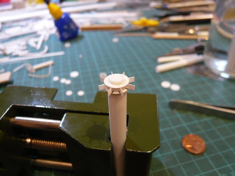
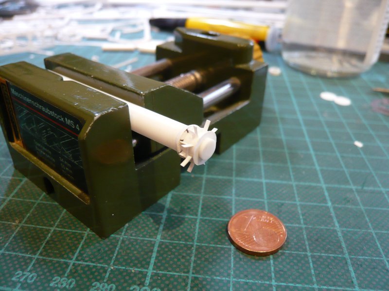
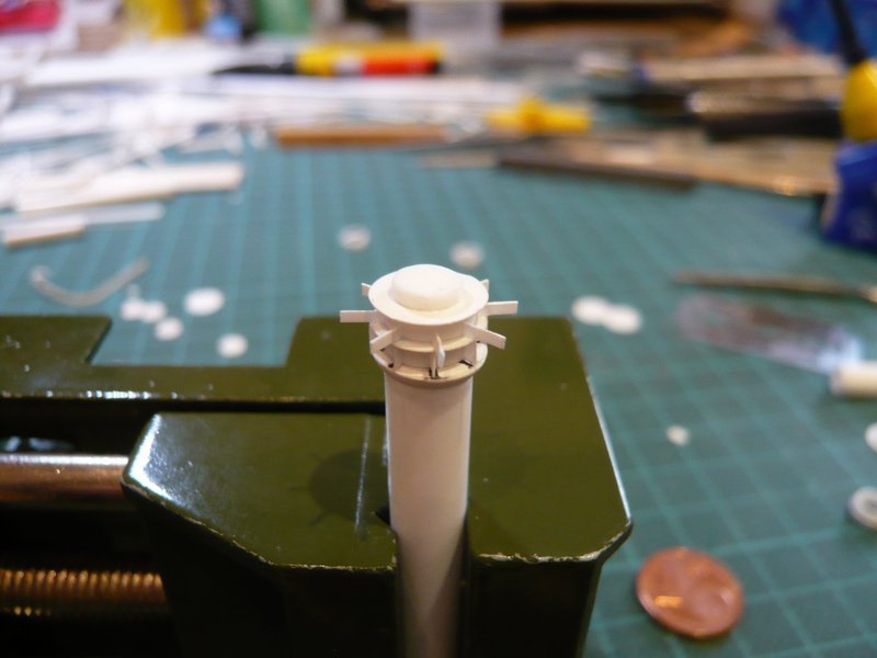
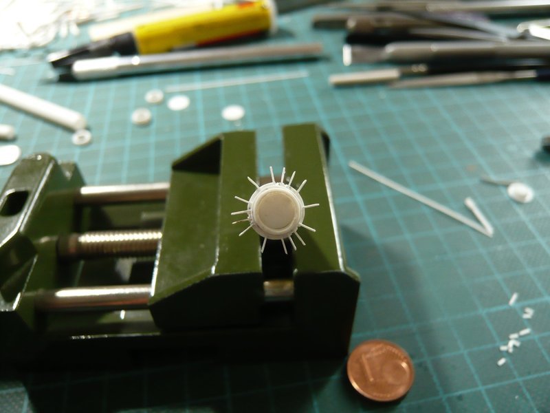
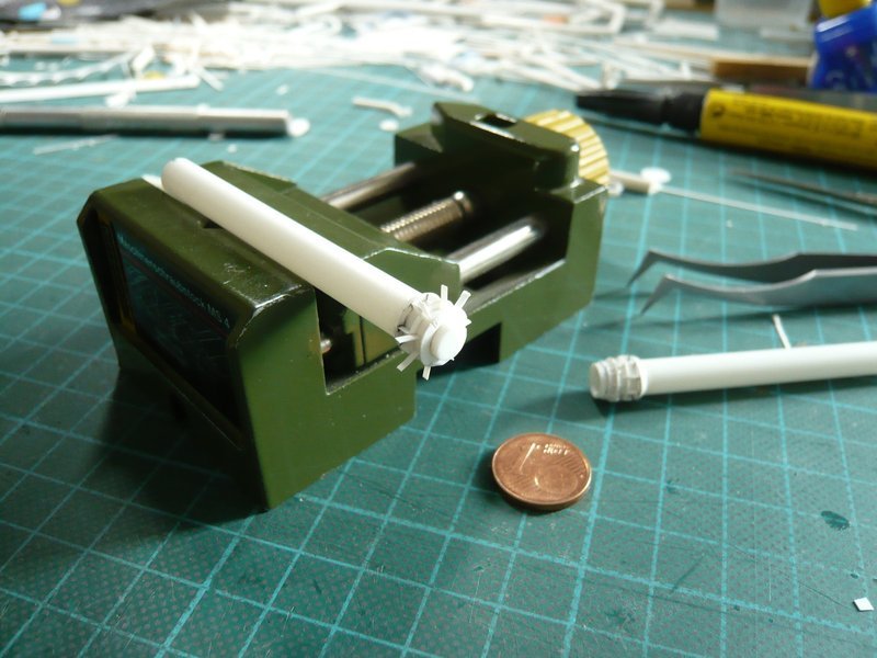
what a crazy part, a true challenge for scratch-building freaks like me.

But working with 3D printing myself is out of the question for me, because one would have to be familiar with 3D modeling, which I can’t do. And for many model builders, gluing the 3D printed parts together is not real model building, but a kind of OOB.

2 Likes

Thanks Brian for your nice compliment,

I also started with OOB model building once, but then I always wanted to try more details, and then you have to improvise and you end up with scratch-building.

3 Likes

Hello everybody,

here it goes on with the tricky puzzle at this Connecting Pipe socket.

Initially, I have made intensive photo analysis once more in order to accurately understand how these 30 ribs are arranged on the circumference of the pipe end, especially since one can always see only certain partial areas on most photos. And after I had reasonably decrypted the arrangement from the optics, the laborious measuring and scaling were started in order to determine the required dimensions and clearances for the scratch-building, I can tell you …

The starting point for the determination the position of the triangular ribs on both sides of the 3rd ring was the 120° arrangement of these rectangular pairs of ribs (0,8 mm x 1 mm) with the holes (Ø 0,2 mm).


Source: Troy McClellan

And on closer inspection one can still see these two slots, one directly between the pair of ribs, and one close to it.


Source: Troy McClellan

But for now enough of preliminary observations.

However, the flipside of these great close-ups of a friend from the ARC Forums is now the implementing of these details in real components because they shrink drastically after scaling, will be seen as equal.

Initially I wanted to take a similar approach in the production of rib pairs as in the previous triangles ribs, for which I have glued two 0,8 mm wide Styrene strips (0,15 mm) again with some overhang with a respective spacer (0,4 mm).

Previously, I had tried to bore this tiny hole (Ø 0,2 mm), which after a few failed attempts still could be realized.

But then these tiny fins (0,8 mm x 1 mm) would have to be glued individually what myself appeared illusory considering my sharpest tweezers, because the rib would then have glued rather to my tweezers. So I had to go without these holes for better or worse which could still be indicated with a fineliner after painting.

And thus, I then made the three rib pairs without the holes.

After that, I have marked the 120° positions and have sawed the small slots.

After that, I have marked the 120° positions and have sawed the small slots, and above it then glued the first pair of ribs with CA.

But already during cutting off the overhang with a razor blade both ribs are broken off.

Probably I have not waited long enough, perhaps the blade was canted, or the adhesive bond was still too weak.

Therefore, the following rib pairs after the CA-attachment I have precautionally still stabilized with MEK.

And then I have cut off the overhangs of the first couple gently and was glad that everything went well,

and looked not bad.

And then the other two pairs followed,

which proves that it works indeed so, if somewhat difficult and stressful, what in this size range is truly but no wonder.

And so next the small triangle-ribs would be on my plan, with whom I fortunately already have some experience, but nevertheless it will probably become a rather swarm.

2 Likes

Hello together,

although the next step went on only a small one, it should become rather stressful.

Here are initially the small 3 mm long strips (0,15 mm x 0,8 mm) for the triangular ribs, 24 of which are needed.

Here 9 ribs sit above the ring, each between the rectangular ribs pairs of,


Source: Troy McClellan

and below there are even a few more, namely 15 pieces. But that was again an undertaking, which has very stressed me.

Firstly, the snippets are difficult to keep in the tweezers, then the front ends were carefully dipped in CA and glued, whereby one but immediately has to meet the marked spot. On the other hand some strips also were glued on the tweezers, so it was all in all again a nerve-wracking game of patience.

The previous intermediate result certainly looks like this, and conveys already a foretaste of what then awaits me on the underside.

The overhangs will be cut off next, and then follow the 15 ribs on the underside of the ring, which certainly should be even more stressful because the already small distances should move together still closer.

But somehow it will work out, I hope.

Now follows the last act of the Ribs Festival at the lower ring of the coupling socket.

First, the upper nine overhangs were cut off, first vertically again, to create more free movement for the 45° cuts,

and then the oblique sections were made very carefully.

Then the still missing three slots were sawed.

And only now I have glued the lower tube segment with the narrow ring definitively with MEK.

Then it went onto the underside of the ring, on which now 15 triangular ribs must be placed.

And since in this narrow space it is hardly possible in order to measure tiny distances, the space was divided much more of the optics ago.

Therefore, I have initially glued in each case the three ribs in the interspaces below the rectangular ribs pairs,

and then in each case the two ribs, which are located below the ribs pairs.

These ribs were then cut off again initially vertically,

and finally chamfered at a 45° angle, which was truly no bed of roses.

And here, finally, is still the view of the mounting position.

And when one considers that about 60 parts were scratch-built at this pipe, then that is really hardly to believe.

But so it’s now almost done, because now only the small support is missing, with which the coupling socket of the pipe is fastened to the inner wall of the SRB Chamber, which can be seen in this image.

3D-rotatable view of this area at nasatech

Source: nasatech.net

Fortunately, there are only two of these feed pipes, so I have the whole procedure only to exercise once again, thank God.

3 Likes

Hello everybody,

and thus back to the coupling socket at the other 36’’ inlet pipe.

This time, however, I did not use a triangular profile for the conical ring (truncated cone) but wanted to try it with the winding-off of the truncated cone, for which I wanted to use a thin Styrene sheet (0,15 mm). In doing so, I had hoped that this ring would let align closer to the pipe than the bulky 1 mm triangular profile.
But for that one needs the winding-off of this part, whose construction however I had to look for initially.
And after I had found a corresponding guidance, I tried out the design on paper on a 1:1 scale. The truncated cone is 1 mm high and the diameters are 6,3 mm and 8,0 mm respectively (see red contour).

Afterwards, I’ve repeated it on the thin Styrene sheet and tried to cut the winding-off with the circular cutter, but because of the small size did not go so easily from the hand.

And that was the proud piece, the edges of which I then had to smooth something.

After sticking of the first ring segments it was then possible to start with the gradual sticking of the winding-off above the ring,

whereby the beginning was important, which had to be fixed tightly.

And then it went with normal Revell glue in small steps round about.

And here is the result, whereby I find that one can already see the difference, because the new ring has leaned up closer to the pipe, and the cone is slightly more flat than the other.

After this, the ribs followed in the usual way, first the eight wider strips between the upper rings,

and then the narrower strips for the underlying triangular ribs,

here after the final circumcision.

That’s it for the moment, because now it becomes again a little more stressful.

3 Likes

Sheer brilliance !!! The fins and rings look great. As a rough idea … How many hours work did just the rings and fins take up ?