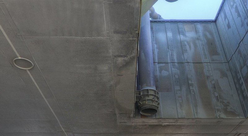
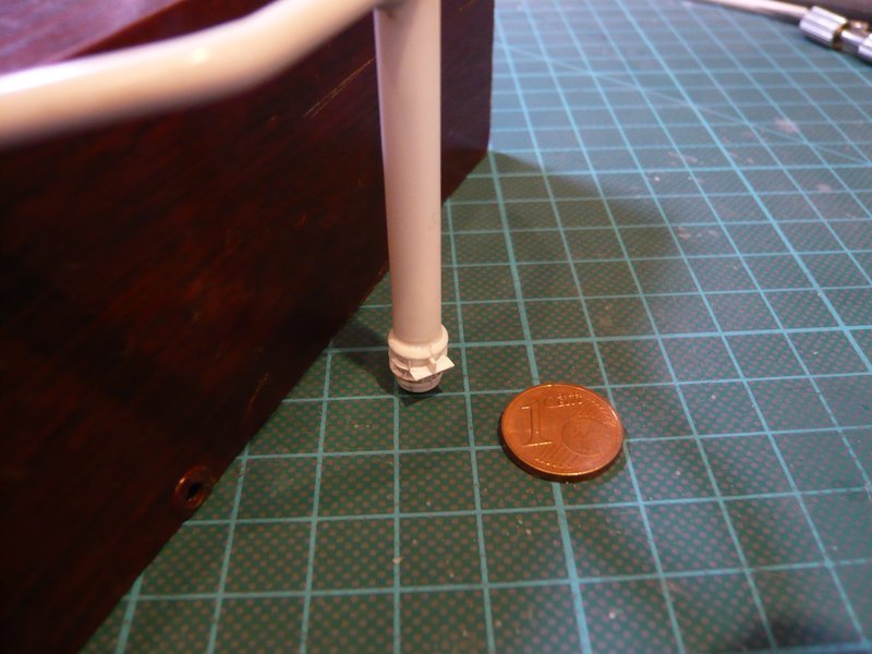
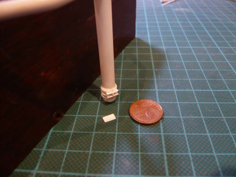
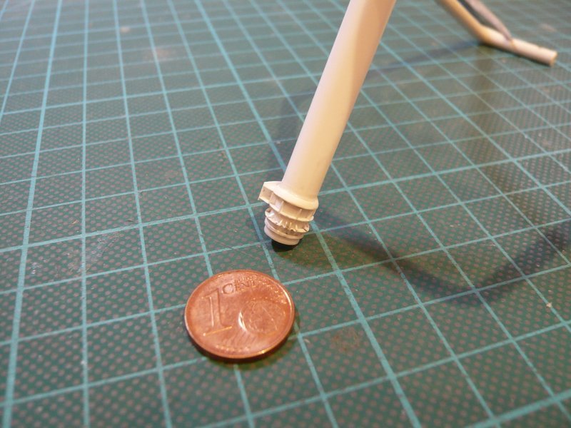
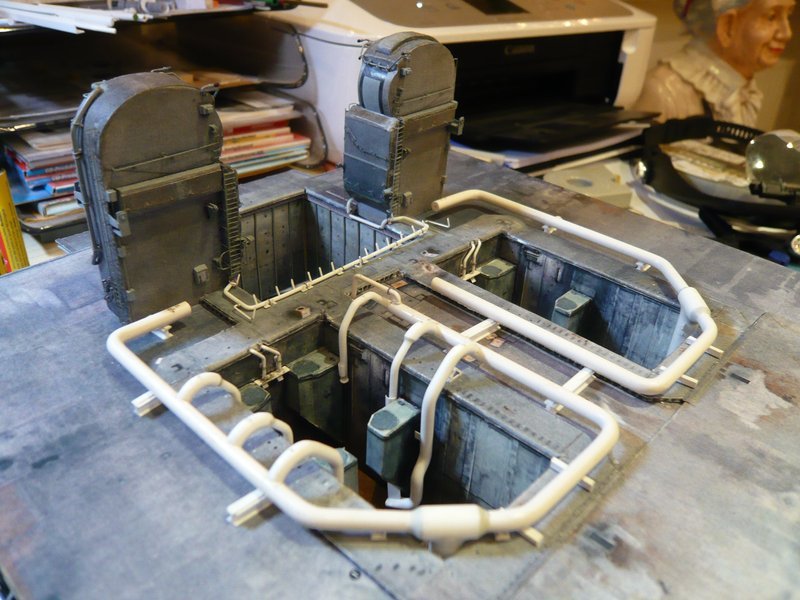
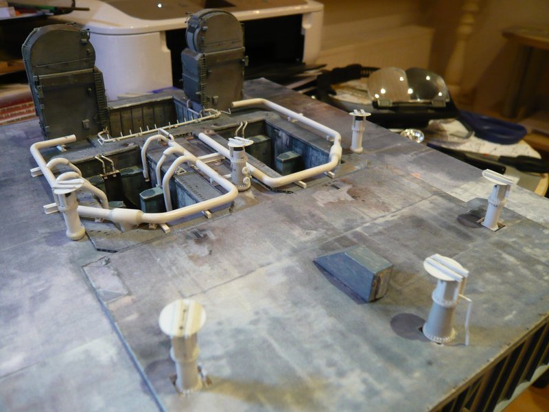
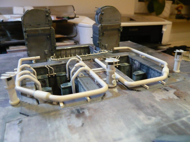
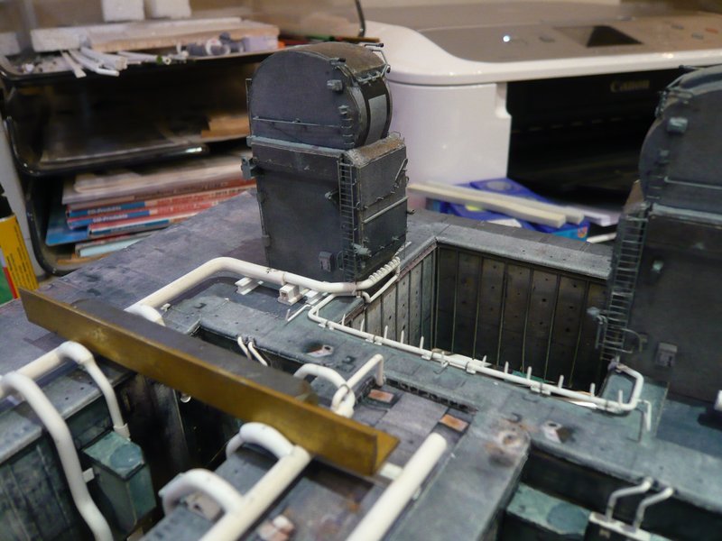
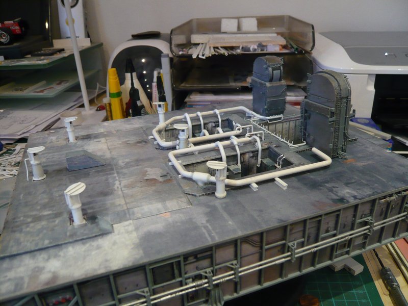
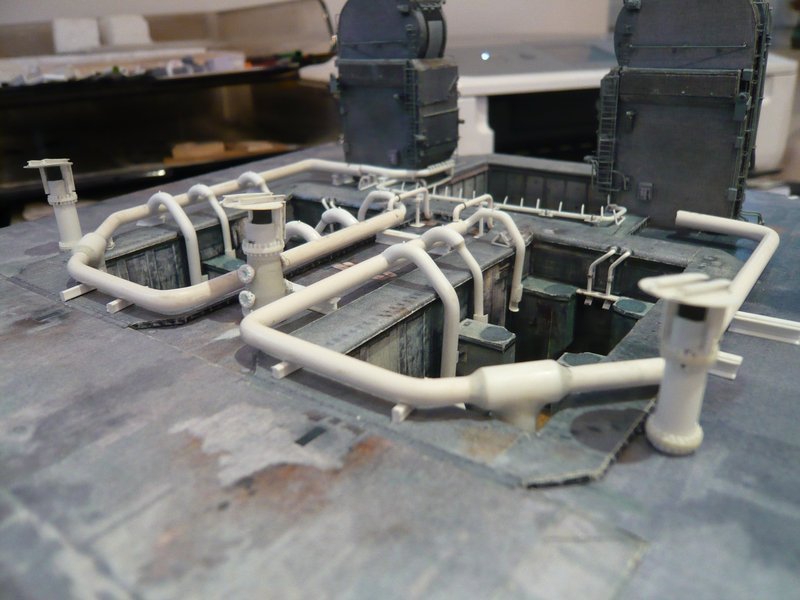
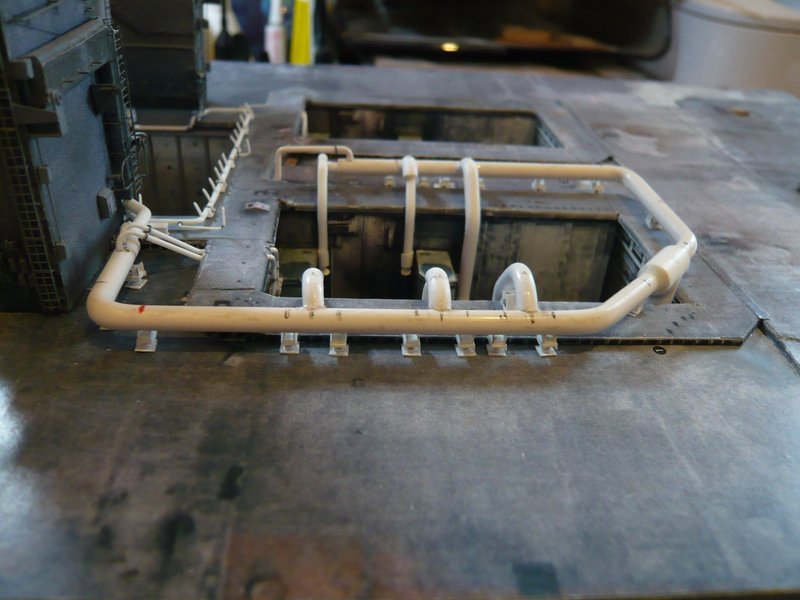
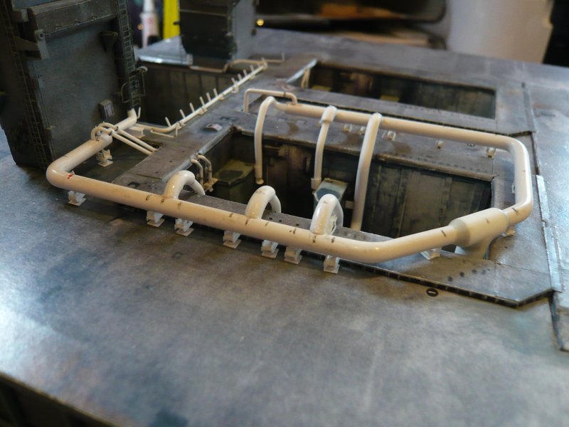
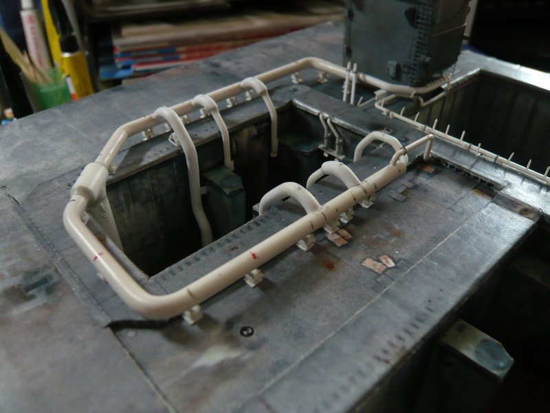
Space Shuttle Launch Complex 39A with Challenger STS-6 (1:144)

Thanks John for your repeated nice compliments.

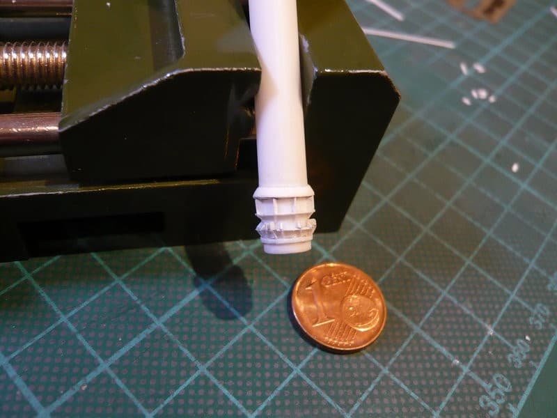
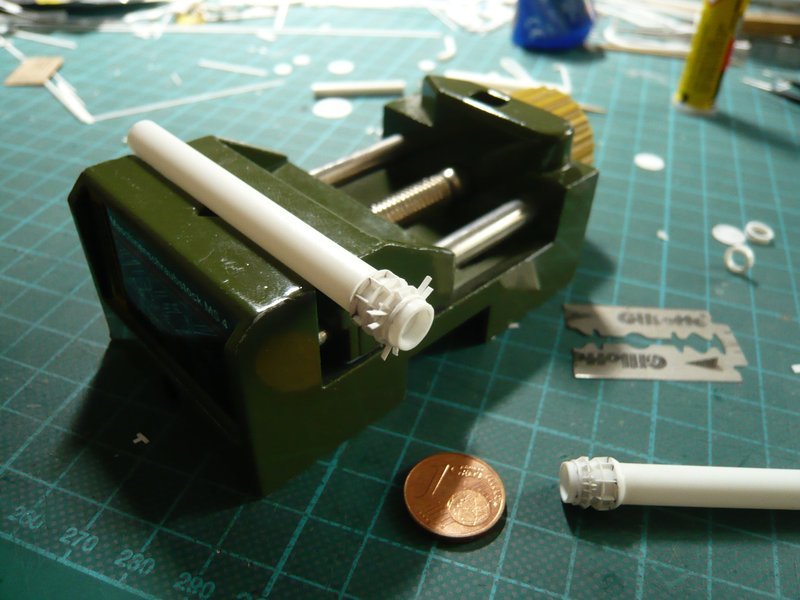
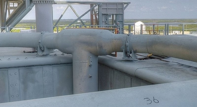
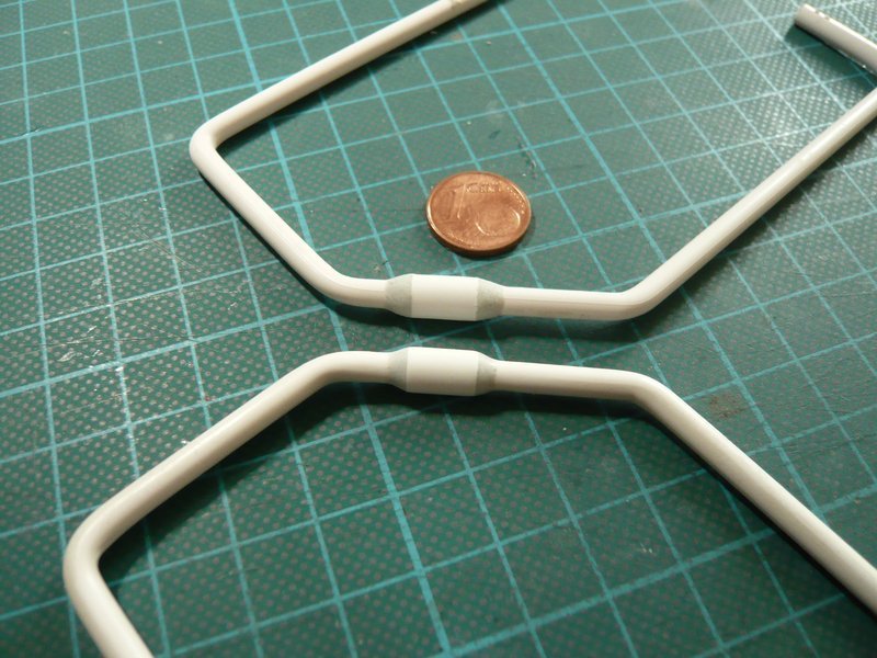
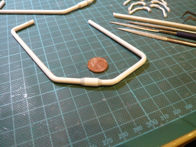
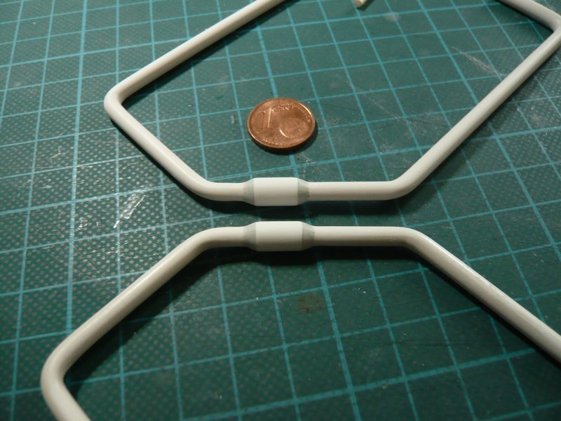
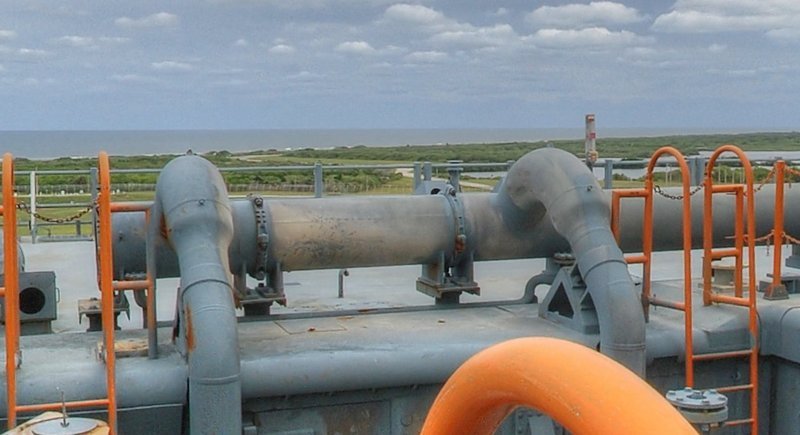
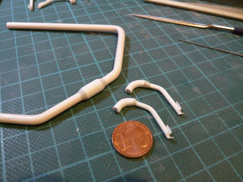
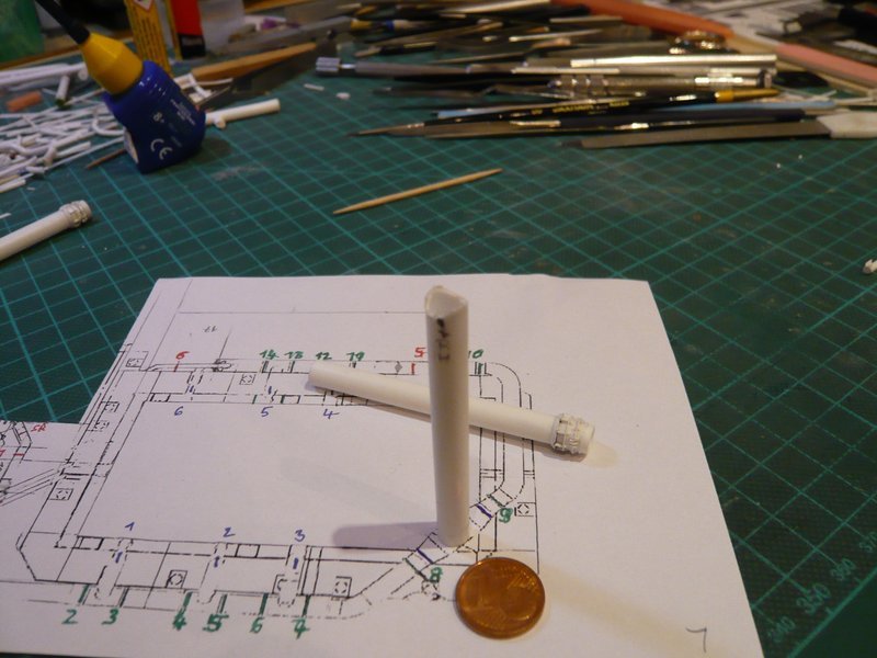
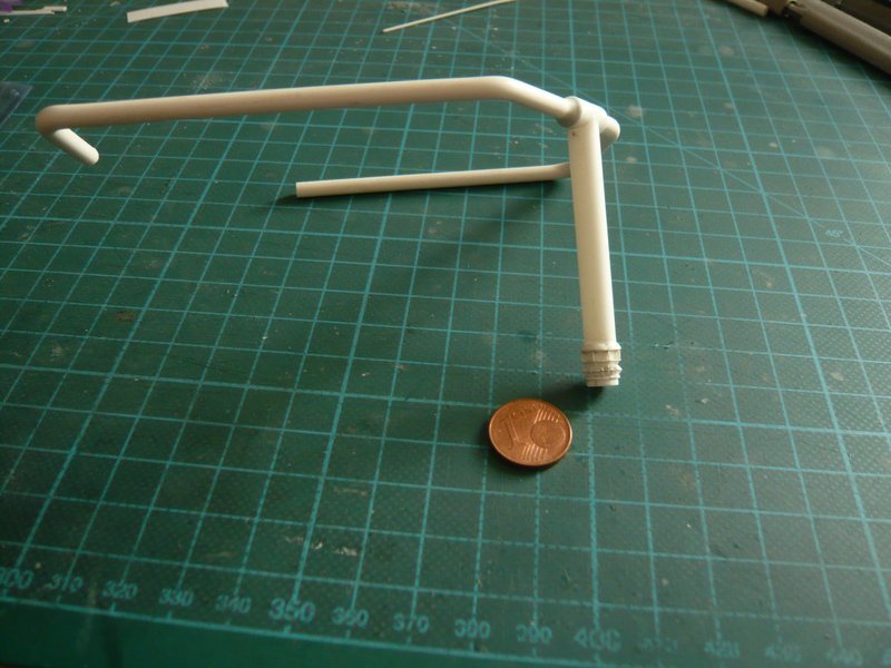
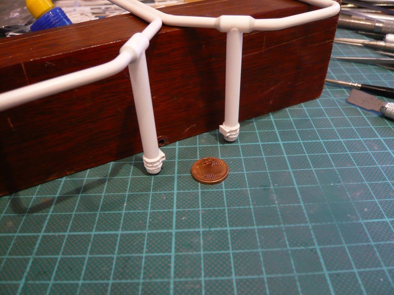
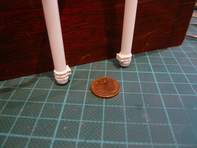
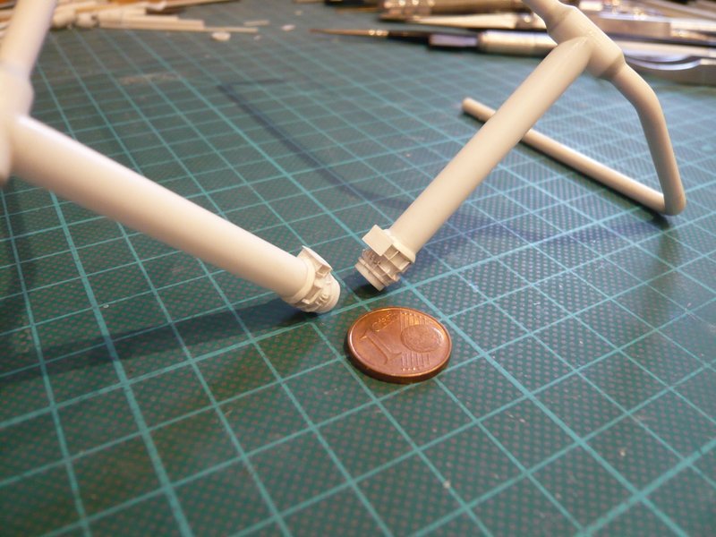
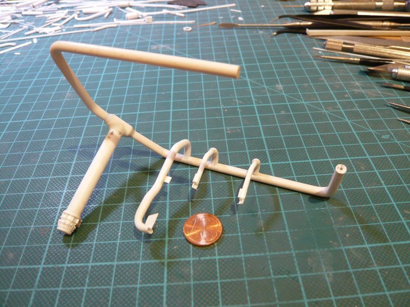
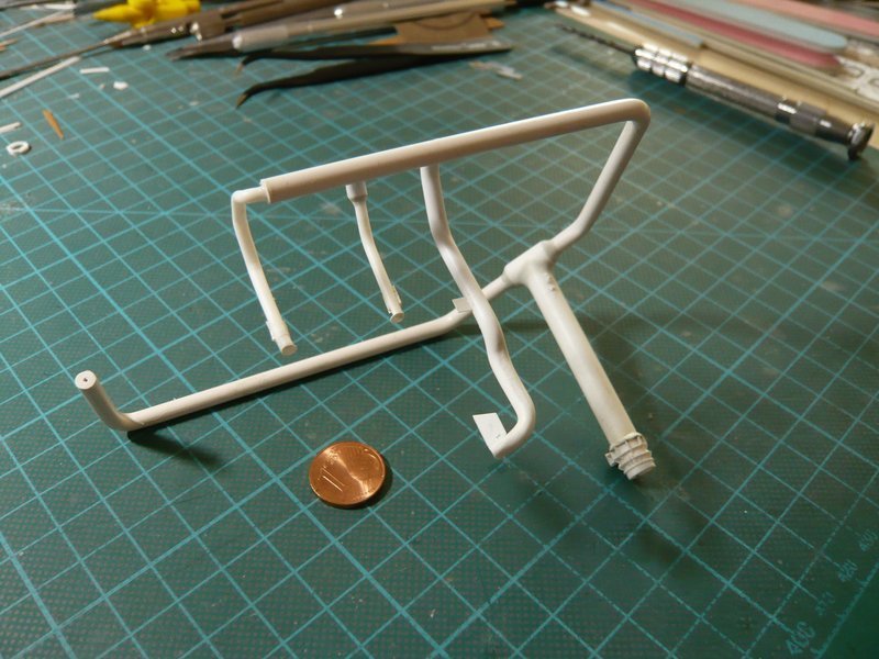
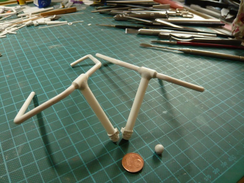
I don’t remember that exactly anymore, because I scratched this 36’’ Inlet pipe about 6 years ago, which extended over more than 6 weeks.

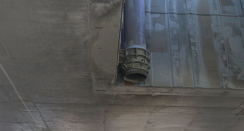
The first phase always includes an intensive search for appropriate photo material and studying it for a detailed understanding of the assembly. The phase of determining the required dimensions and working out possible solutions for the scratch-building, as well as the search for appropriate materials, is even more complex.

And only then does the actual construction phase follow with Trial & Error, building prototypes, test fits, etc., until I’m finally satisfied with the result.

Of course, constant taking photos and posting the reports are also involved, whereby the photo representation is also very time-consuming.

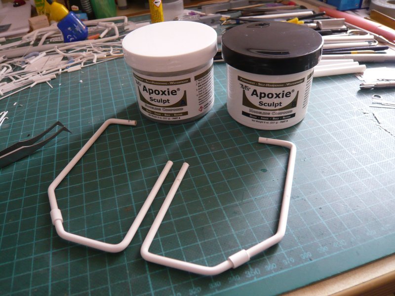
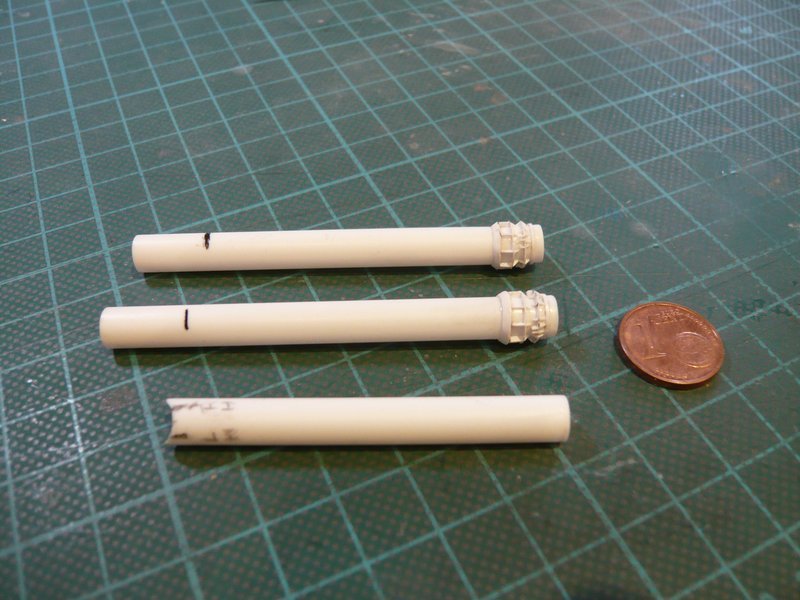
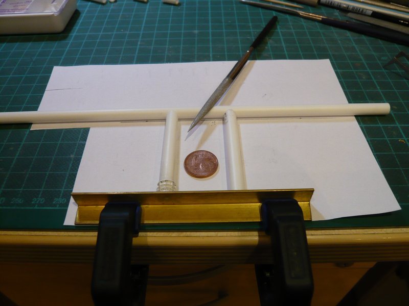
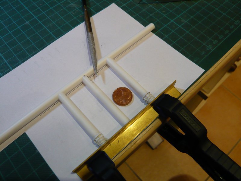
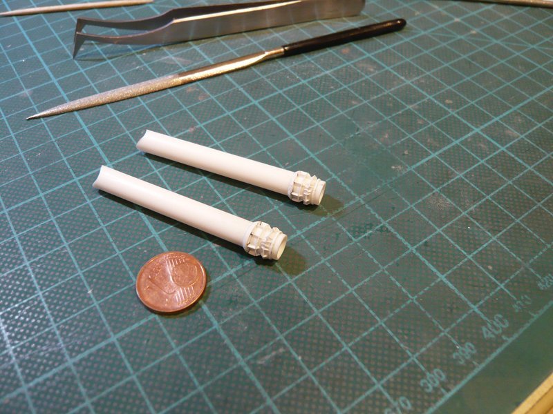
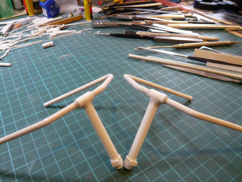
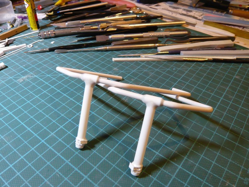
Here is still once more a first image from the beginning,

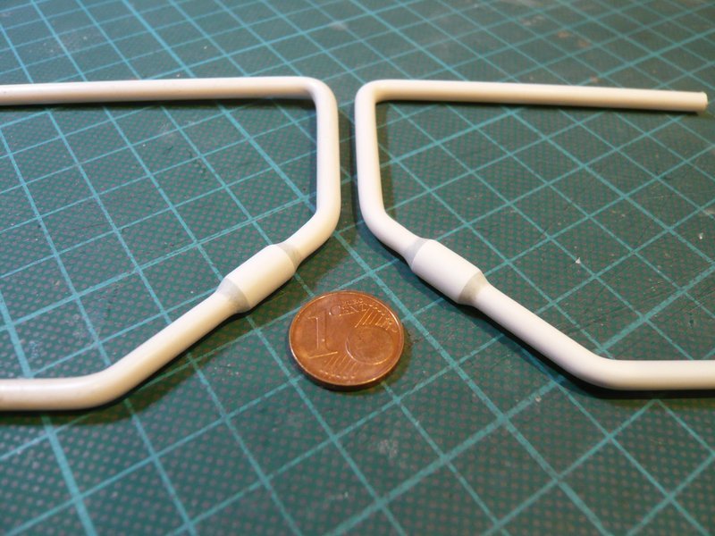
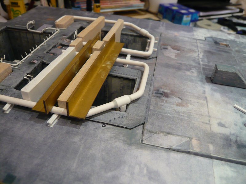
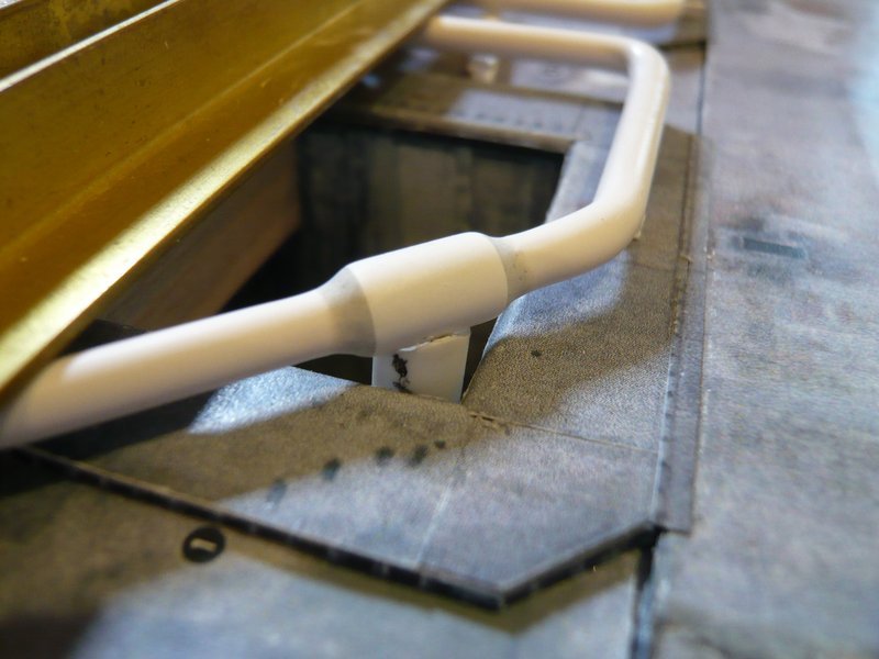
until the completion of the first of two inlet pipes, which then has still to be connected to the ring line.

It was a long and winding road … All in all a long way, but only a small step through the endless SSWS Labyrinth.

Luckily, following the same way once more is always a little bit shorter.

2 Likes

Hello everybody,

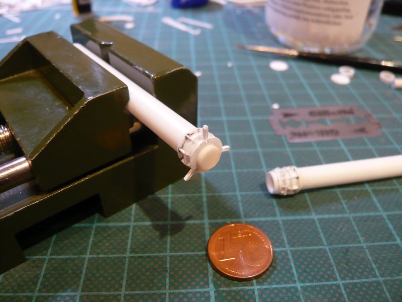
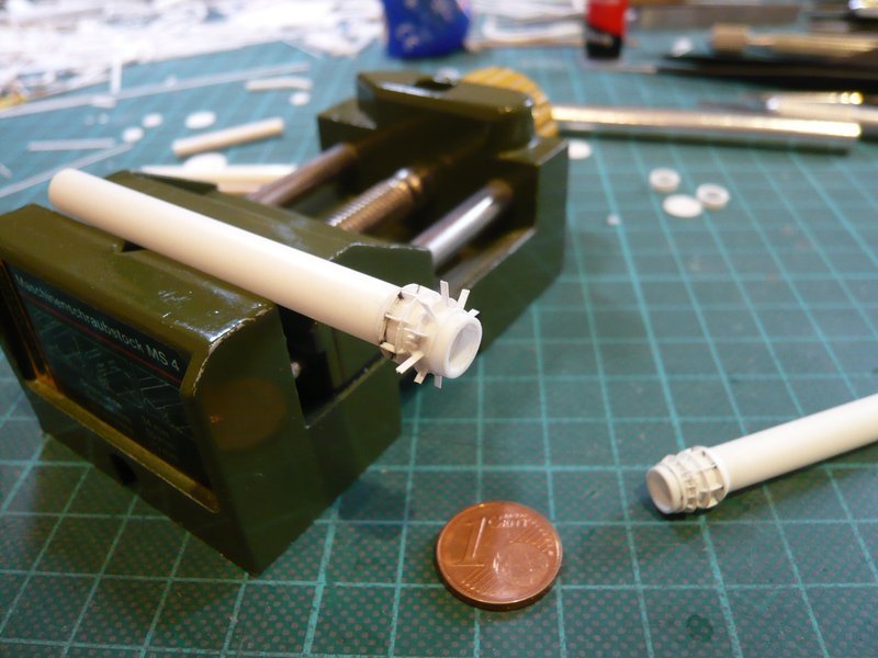
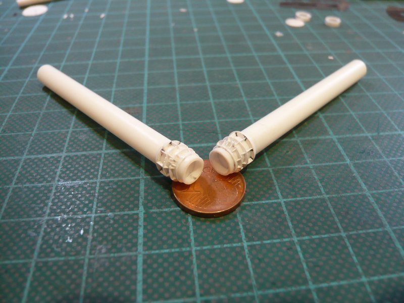
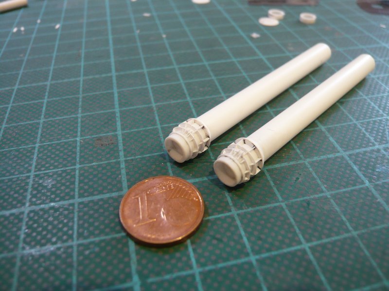
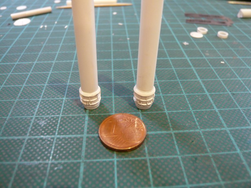
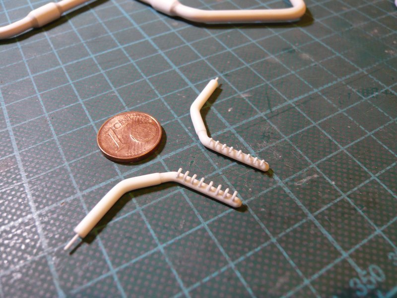
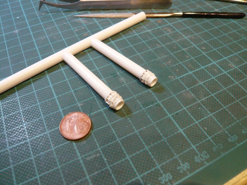
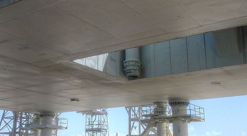
now I will finally complete the coupling socket of the second Inlet Pipe, on which still lacked the rectangular rib pairs and the triangular ribs on the lower ring.

After the rib pairs over the slots were glued and cut off,

the nine ribs between them followed in well-known manner. Thereafter, the corresponding ribs sitting below them on the underside of the ring were glued,

and finally bevelled.

And only then I have glued the remaining six ribs below the rib pairs, which was easier for reasons of space than for the first inlet pipe, where I had first glued all 15 ribs, which made the bevelling quite difficult.

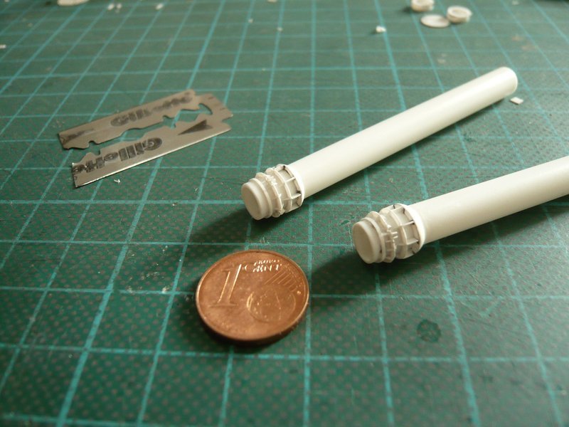
And after the bevelling of the last six ribs, this tricky fiddling was finally done and I’ve felt relieved.

Therewith all pipes and outlets of the SSWS have been completed exept some missing Pipe Supports, wherewith their assembly at the ring lines can actually follow, which could become very interesting, since all transitions not only are to glue but also should be modeled by using Apoxie Sculpt.

I will begin with the transitions from the now finished 36’’ Inlet pipes (Ø 6,3 mm) to the two 24’’ Ring lines (Ø 4,0 mm),

3D-rotatable view of this area at nasatech

Source: nasatech.net

whose connecting sleeves are finally positioned and glued to the ring lines.

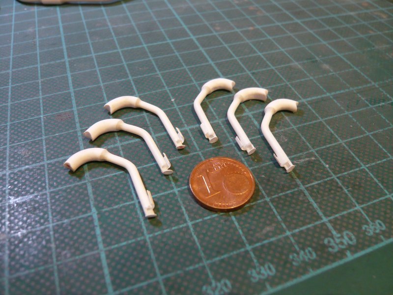
Then follows the modeling of the transitions of these six 18’’ outlets (Ø 3,2 mm) with the tapers to 12’’ (Ø 2,0 mm).

And then there are still these two outlets at the end of the ring lines behind the TSMs with the tapers to 16" (Ø 2,5 mm) and then to the 12" Nozzle pipes (Ø 2,0 mm).

These four rear 18" outlets (above) and the two front 12" outlets (below) have no tapers and are already ready for assembly.

When these transitions are modeled, the outlets can finally be glued onto both ring lines. And then these connecting points must also be modeled.

So, all in all, this looks like an extensive Apoxie Sculpt Session, at which we then will see us again.

4 Likes

Hello everybody,

so, now I have begun with modeling the transitions, first with the transitions on the two ring lines,

3D-rotatable view of this area at nasatech

Source: nasatech.net

which are still quite accessible and handy.

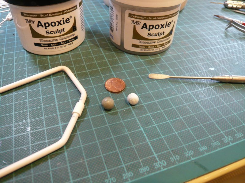
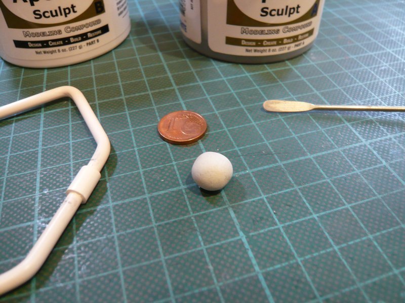
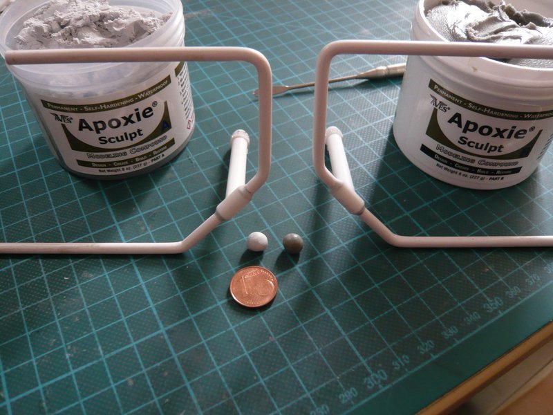
First, two equally sized marbles were formed from the two Apoxie-Sculpt components,

which were then kneaded until they were completely mixed, which can be seen in the resulting white color.

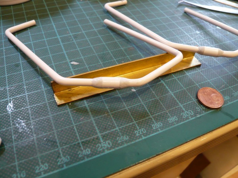
And then the transitions were modeled on the two sleeves, which can be made at the same time.

Thereby it is helpful not to take too much Apoxie Sculpt and then keep it in the mean time occasionally to moisten in order to stay flexible.

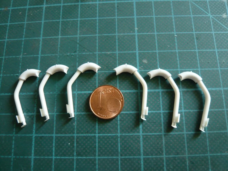
Then followed the six 18’’ outlets from the ring lines into the SRB shafts, and this action was then much more tricky and stressful.

Since these parts can hardly be held in the fingers, but they still have to turn and turn around constantly, this was absolutely no nerve balm.

Thereby one thing turned out to be particularly hindering, and these were the tiny nipples on the bows and the lower baffles, which I should have installed better afterwards.

As a result, the transitions have not worked out as good as one can see. But I wanted to make use of the time before the mass hardens too much, and so I have stayed the course.

But now I leave all this dry and then I will rework the transitions separately by sanding.

Well, seen in hindsight, I have applied a bit too much Apoxie Sculpt (AS) and now have to sand off something, but this is easy to do because the AS is very dense and extremely fine-grained after the hardening.

But this effort would have been significantly reduced if I had already formed the transition better in the damp state and adapted it to the rather concave shape. But afterwards one is always wiser.

Therefore I have to shape this concave transition with different files, sanding sticks and finally with Sanding sponge (2000), which is already a bit arduous, but what the heck!

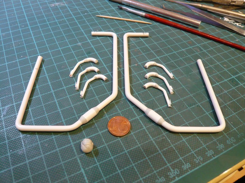
Here already a first picture of one of the transitions, on the left the somewhat chubby modeled form, and on the right the post-processed form, which looks optically already quite well.

In fact, the transition could be even something shorter if I exactly look at the image once again.


Source: nasatech.net

At the transition on the second ring line (above) I was then already somewhat more relaxed, since I knew that there was something significantly to sand off,

as can be seen here at the right transition.

And these are the finished transitions.

And now followed the transitions at the six 18’‘-12’’ outlets, which also have a slightly concave shape.

3D-rotatable view of this area at nasatech

Source: nasatech.net

Although there is less material to remove, but their handling is more tricky due to the small size.

For comparison, I have put a raw state next to it.

And next the remaining five outlets will be reworked.

1 Like

Hi guys,

as I have already indicated, I have now after all brought myself to shorten the transitions at the 36’’ outlets of the ring lines, and I imagine that they fit better now into the overall picture.

And these are the 18’‘/12’’ outlets with the reworked transitions,

And here are finally the finished transitions at the 16’‘/12’’ outlets to the both nozzle tubes.

And as next step, the final assembly of all the outlets on the two ring lines begins then with the mounting of the inlet pipes,

3D-rotatable view of this area at nasatech

Source: nasatech.net

whereby it again depends on the stable fixation.

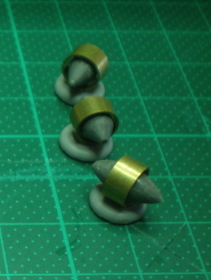
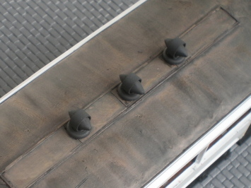
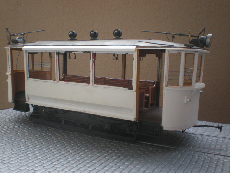
Bravo, very nicely tapered transitions! Please forgive the photo-bomb but I felt your pain intensely, I remember how many hours it took me to make these 3 tram roof-ventilators…

T377 - P5310011

T383 - P6020030

I didn’t trust myself with putty, instead finding 3 solid styrene cylinders in the spares box and paring/sanding each end down almost to a point. You probably also thought about a miniature lathe, but difficult or impossible to secure the object in it. Yet equally difficult to hold in the hand for very long. The worst part is replicating several identical items when it’s all done by eye – one only sees the comparative imperfections, they never all look exactly the same. Except yours do :+1: :+1:

1 Like

Thanks Tim for your compassion, I can understand your problems.

The difficulty of reproducible making such multi-bent parts parts as with the SSWS increases with the number required parts as well as the changed shapes of the outlets with the tapers. You really have to bite yourself through that.

And that was only possible with my Balsa & Bending technique by using Balsa templates and a Hot air gun.

I’ve also experimented with some types of putty, but found them too sticky and smudgy. And only with Apoxie Sculpt I was completely satisfied.

1 Like

Hello together,

before the assembly of the inlet pipes, however still had to be determined their exact length, so that they fit exactly into the corners of the two SRB shafts and end with the coupling sockets at the MLP bottom.

For this purpose, the tubes at the upper end must be shortened. At this place, the half-round recesses have to be sanded, whereby the special position of the coupling stubs in the pallets must be observed. And that looks exactly that the (still missing) Pipe support sits over one of the three 120° staggered locking points (the rectangular rib pairs) on the inner SRB wall, as can be seen here a bit more distinctly.

3D-rotatable view of this area at nasatech

Source: nasatech.net

And as I wanted to be sure during shortening of the inlet pipes were shortened, I used a somewhat longer dummy and sanded the necessary recesses at the end.

Then I have sticked this dummy with some Pattex under the outlet of the ring line and in this way could mark both the end point of the pipe at the MLP bottom and the corresponding position of the recess at the connection point.

And to this length, the supply pipes could now be shortened with a quiet conscience, and then also the recesses could be sanded at the right place.

And this is what it looks like,

and the same length should have the outlets too, therefore the interim examination at the end stop.

And the adjustment at the connection points also looks good.

So, that’s it for today, and tomorrow the inlet pipes are then mounted on the ring lines.

3 Likes

Hello everybody,

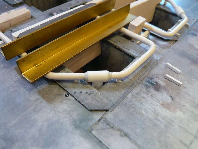
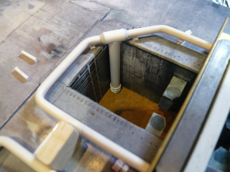
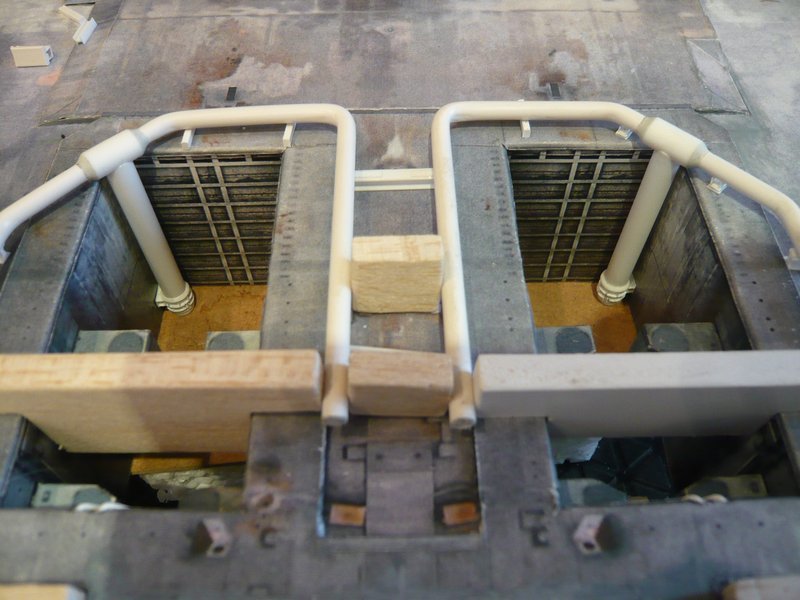
meanwhile the assembly of the inlet pipes has taken place, whose result I would like to introduce you briefly.

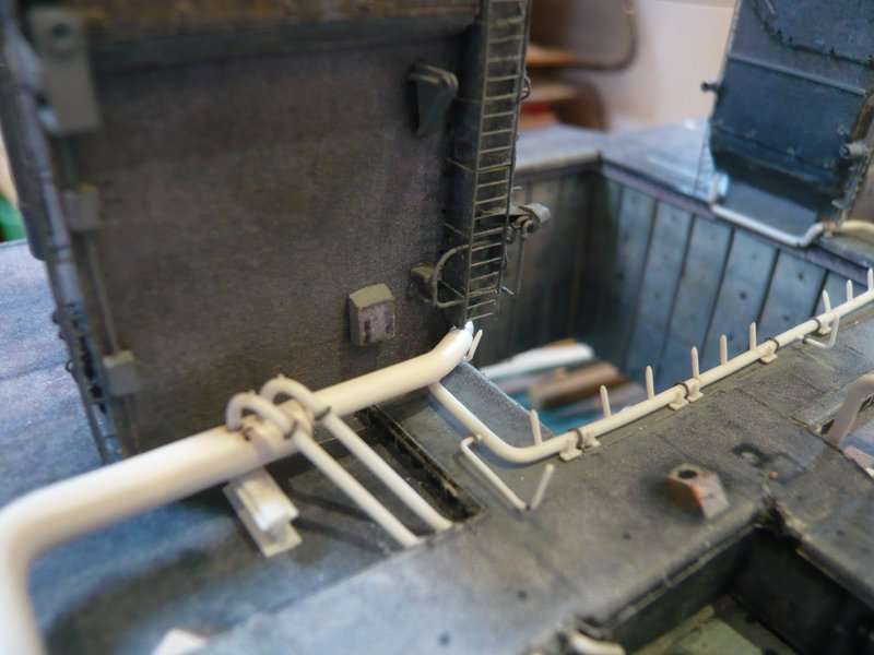
The positioning and simultaneous bonding of the pipes under the ring line was somewhat tricky, but finally has worked quite well.

Important was the vertical alignment of the pipes in the shaft corner, for which the ring line was weighted, in order to avoid slipping.

Now the bondings have only still to dry through,

then these transitions can also be modeled with Apoxie Sculpt.

And then the supports can also be adapted to the coupling connectors.


Source: nasatech.net

That’s it again for the moment.

2 Likes

Hello everybody,

now to the supports at the end of the Inlet pipes. How they look, I know now, so I could start after the determination of the dimensions of the individual parts with the implementation. However beforehand the dimensions must be checked as always.

In the meantime, the pipes firmly adhere to the ring lines that one has relatively stable conditions for testing their fitting.

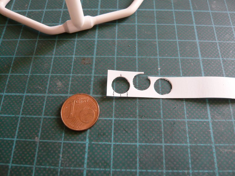
At first I have cut two small sickles out of the remains of the cut-out 8 mm discs,

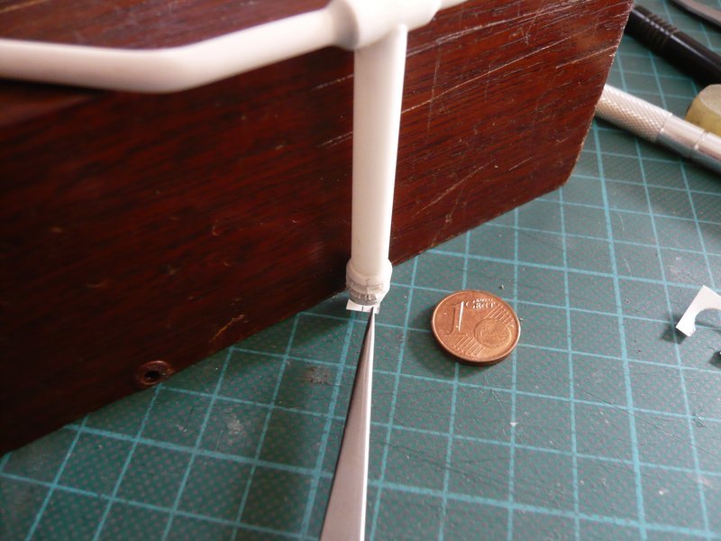
which now have to be glued to the two rings above the locking plates on the outer wall of the shaft, the question is only how to do this without slipping?

Holding the tiny sickle to the ring with the tweezers is relatively difficult, especially since the line-shaped gluing site would be probably rather unstable.

On the other hand, a middle strip (1 mm x 1,8 mm) would be very helpful,

because it would serve as a stop at the same time.

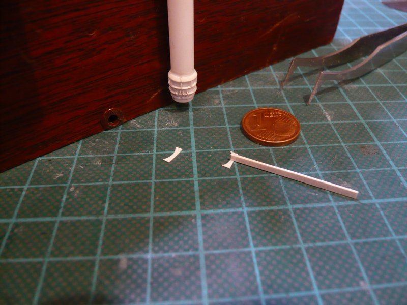
Here the part is already glued,

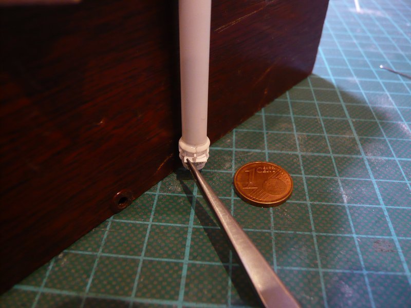
so that now the upper sickle could follow. And now only the small base plate is needed for attachment to the shaft wall,

which can be seen here,

3D-rotatable view of this area at nasatech

Source: nasatech.net

Now the first support is finished,

and also the test at the shaft wall looks quite well.

And next the support on the other inlet pipe can follow.

2 Likes

Hello everybody,

meanwhile also the second inlet pipe has got its support,

and both pipes fit well at the walls in the SRB chamber corners.

Next followed the modeling of the transitions from inlet pipes to the ring lines, as usual again with Apoxie Sculpt.

After thorough mixing of the two components, the mass was rolled into two thin rolls and modeled around the transitions. And as you can see at the rest of the pellet, I had misjudged it again, since the half would have been enough.

Now I have to wait until the mass has hardened, in order to be able to shape the final contours of the transition, but there is something to be sanded off again.

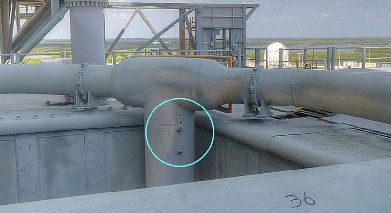
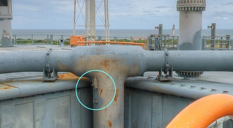
And therefore now to these two small details, which I at first did not pay much attention. But now I’ve figured out wherefore these parts are mounted there.


Source: nasatech.net

BTW, strange, now my web linkage in the image to the 3D-rotatable view of this area at nasatech works.

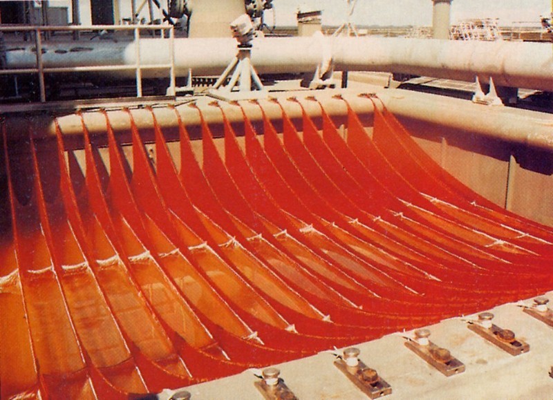
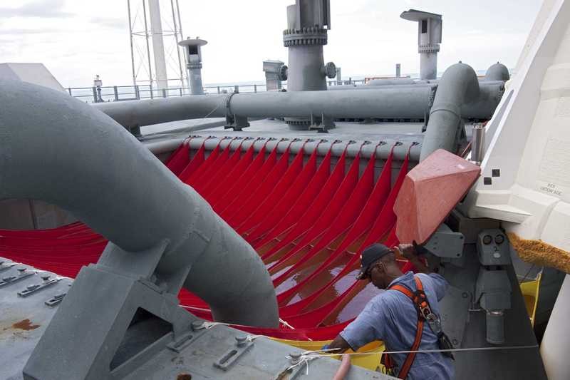
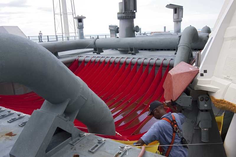
These are brackets specifically for the carrying ropes of the two Water bags, which are attached behind the inlet pipe.


Source: flickr.com

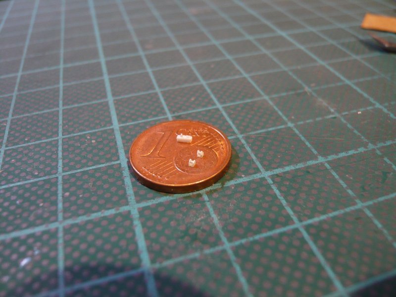
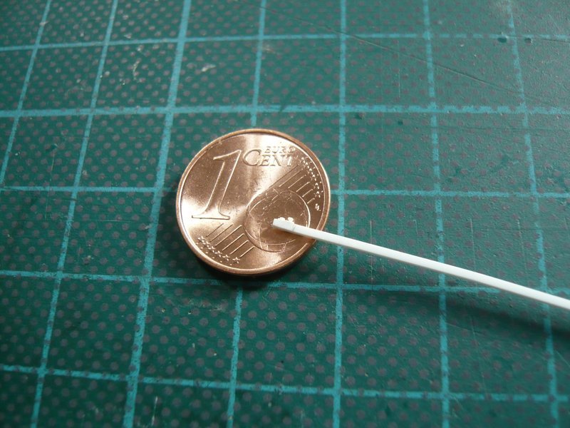
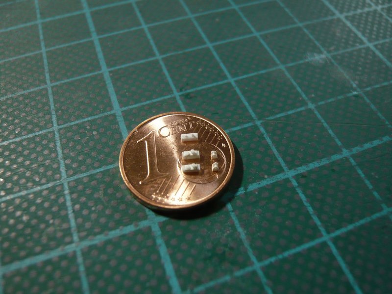
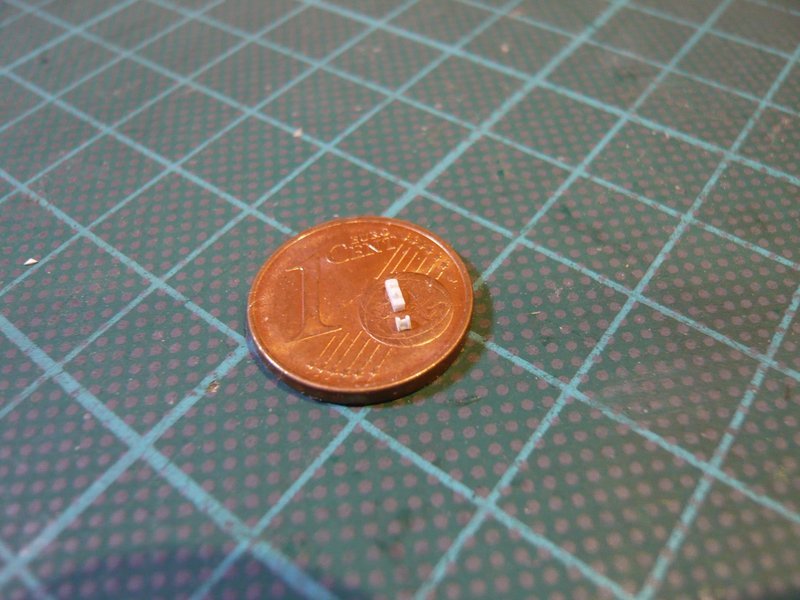
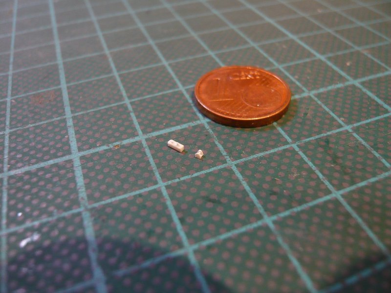
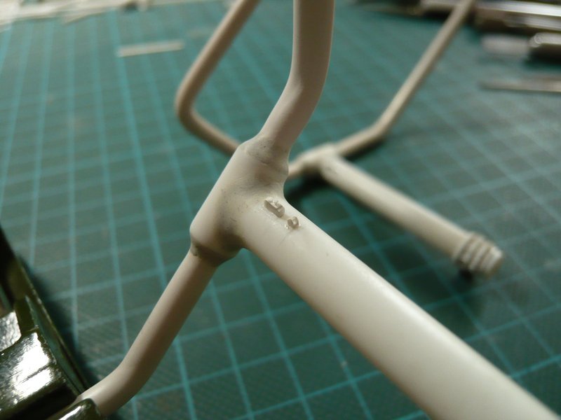
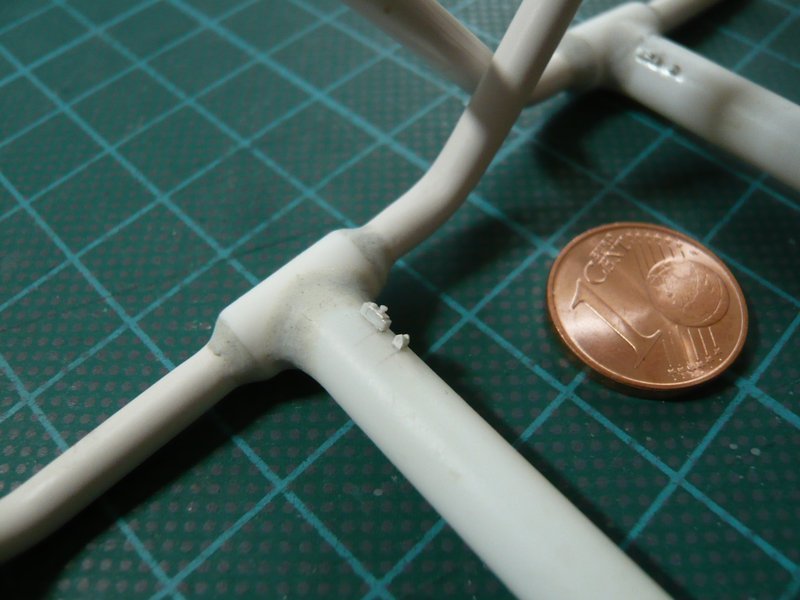
The retaining strip is only a small strip (0,8 mm x 0,8 mm x 2 mm) and the deflection pulley even more tiny, but I simply want to try, whether it can still be scratched.

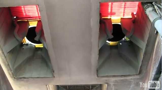
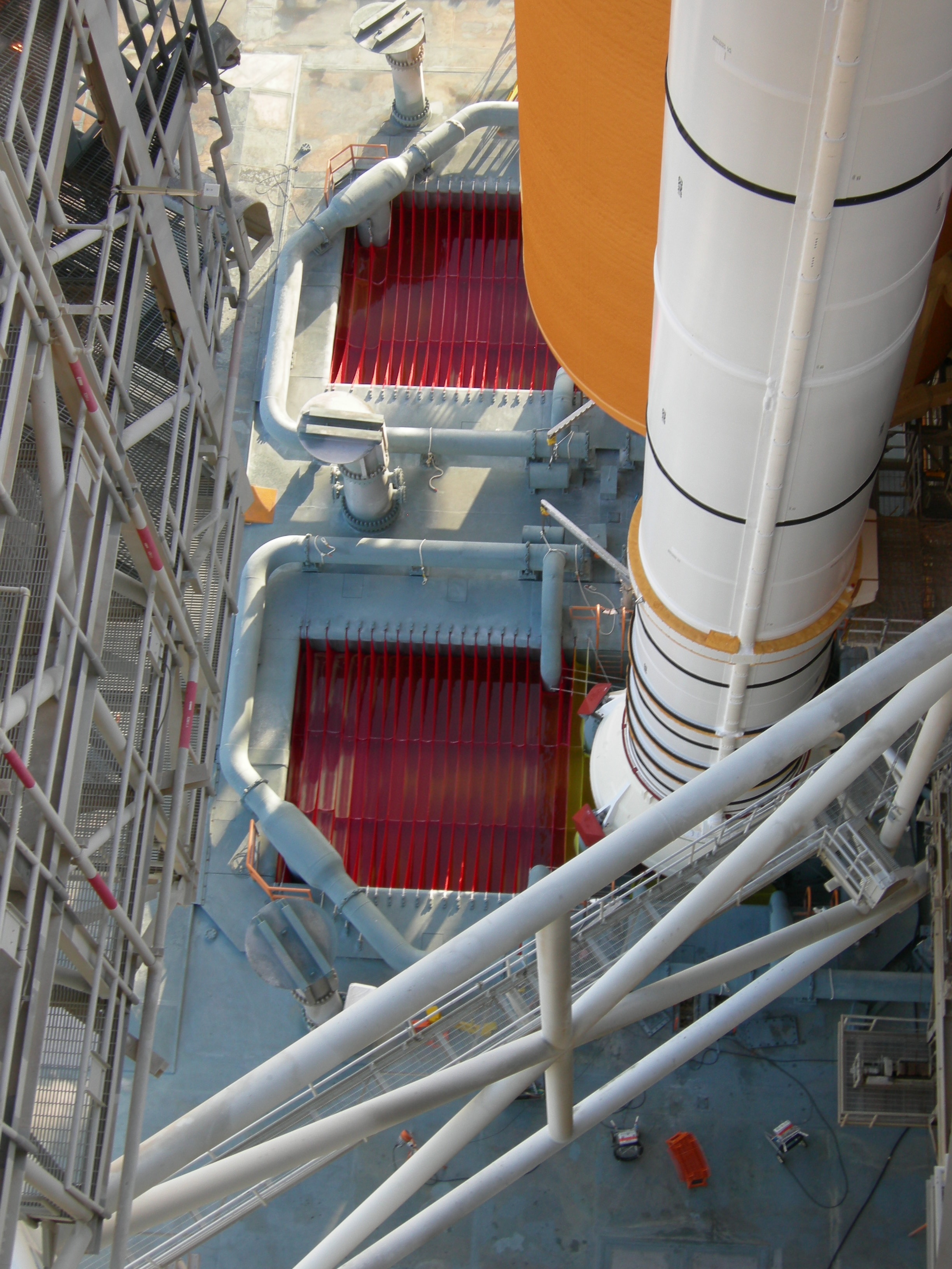
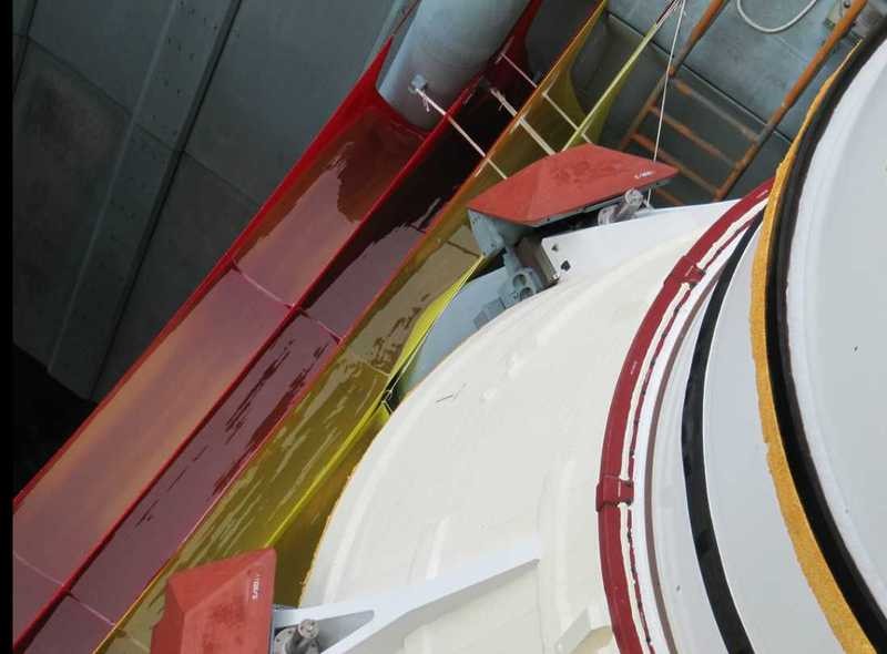
The Water bags are plastic bags filled with water, which were hung in the two SRB Exhaust chambers and were also to absorb the pressure wave from the booster ignition and prevent the reflection of pressure and sound waves.

This so-called SRB Ignition Over-pressure Suppression System is a subsystem of the SSWS, which due to damage to the Columbia during launch was retrofitted after the first Shuttle mission STS-1, as was the ring line system with the outlet pipes. The STS-1 initially only had the six Rainbirds.

Here are some more interesting images.


Source: NASA


Source: NASA

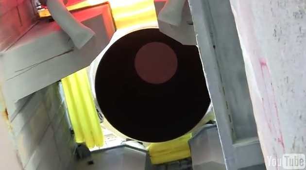
And here from a YouTube video from the perspective below the MLP.

I will come back to the Water bags in the foreseeable future.

3 Likes

Hello everybody,

next followed the final processing of the previously modeled transitions by removing superfluous material, whereby I tried to gently approach the concave shape, which can be seen at the left transition,

and finally at both inlet pipes.

And so back to the fixing rail and guide roller at the upper end of the inlet pipes, which I have actually tried.

3D-rotatable view of this area at nasatech
Source: nasatech.net

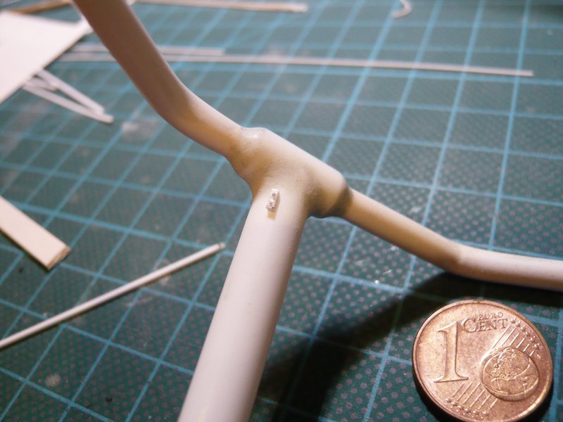
For this purpose, I used an Evergreen profile 0,75 mm x 0,75 mm for the fixing rail. For the bollard and the locking screw two Ø 0,3 mm holes were drilled and Ø 0,3 mm rods were sticked in.

And so my first prototype (2 mm) of the fixing rail looks like,

which was tested and should fit already well.

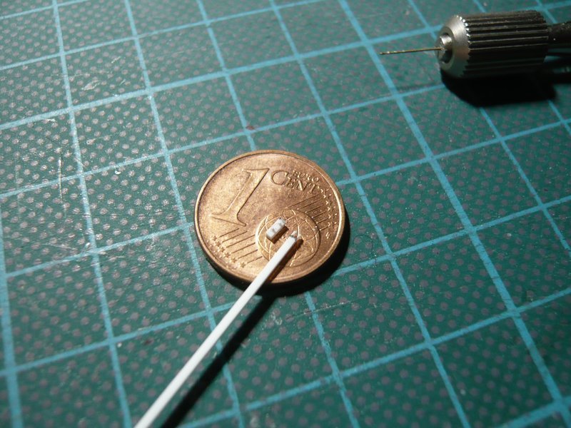
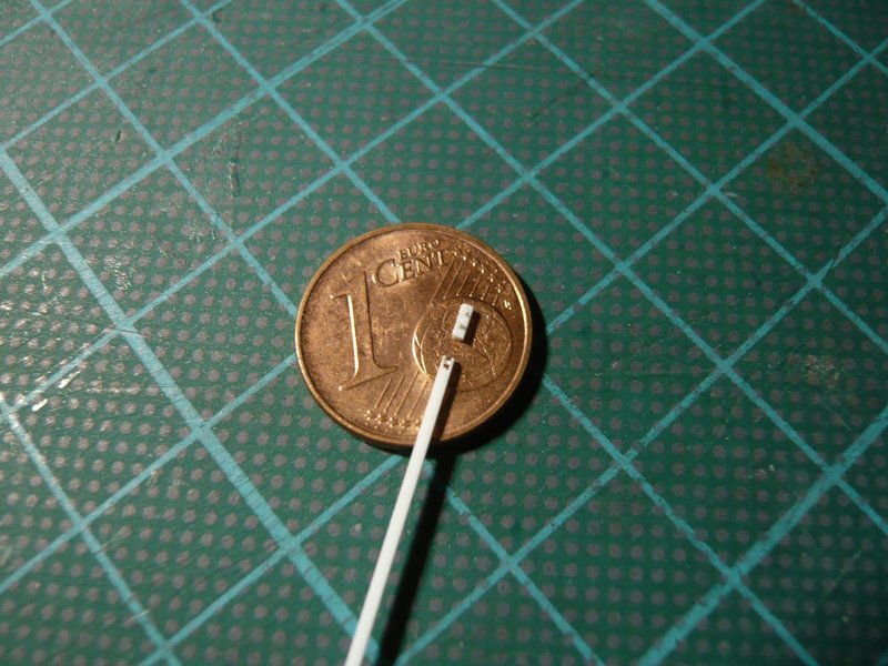
For the guide roller, I first tried to saw a central recess into a 0,75 mm x 0,75 mm profile, which is not so easy with this “width”.

It would be even more difficult to drill the necessary holes for the roll (Ø 0,3 mm) in these minimal overhangs.

That is why I re-drilled a little bit next to it and sawed the central recess a bit further, after which the bar for the roll let insert itself, albeit reluctantly.

Subsequently, the rod was glued with MEK and separated off, and the overhangs were shortened and beveled.

When this tiny stub was cut off, however, the mishap then happened, because after that, it was unfortunately no longer findable.

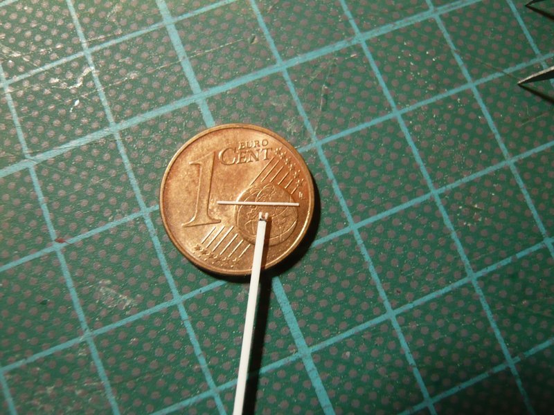
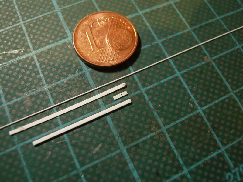
So new game, new luck, but this time according to a modified method, in which I wanted to stick two 0,75 mm wide strips (0,15 mm), which I previously had drilled, on both sides of a rectangular strip 0,5 mm x 0,75 mm (bottom).

The longer strip I have bevelled with the razor blade on both sides immediately in front of the bore to simulate the triangular shape of the side walls.

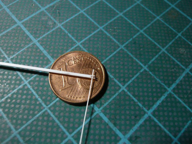
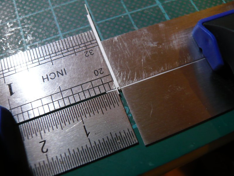
Then, the sides were threaded onto the bar, the rectangle strip was interposed and everything was fixed together between four steel scales, after which the composite was carefully glued with MEK.

To do this, it is sufficient to wet the parts only with the MEK brush as the MEK penetrates into the cracks and immediately performs its function.

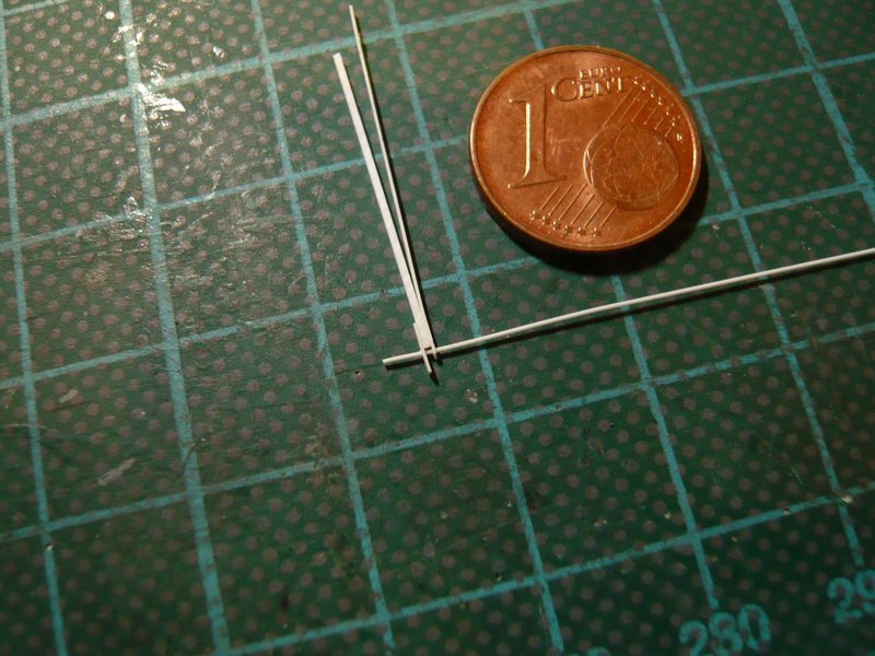
Then only the triangular shape with the razor blade was cut off at the front projection, and also the rod on both sides and the rear part.

And so the two parts now look, which seems to be quite useful,

or what do you mean?

Well, these are only two tiny details, but they also had it in themselves again. The guide roller with < 1 mm lies in an area, which I really no longer wanted to scratch, but since there are only two parts, these exceptions are to confirm the rule.

2 Likes

Hello together,

in the meantime, I have also finished the second guide roller, which is why I am delighted, because these tiny parts can really hardly be handled sensibly, and one always runs the risk that they suddenly fly away - Goodbye forever!

So far, so good, but with the previous fixing rail I was still not quite satisfied, since this is still somewhat more structured than my first prototype, which is why I still want to offer an update.

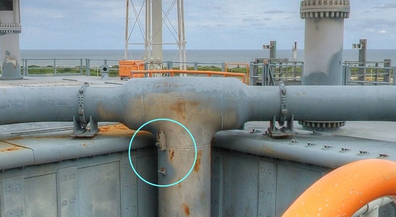
When looking closely, it can be seen that the fixing rail consists of a base body on which a clamping strip with a small bollard for the tensioning cable of the Water bag sits, whose seat can be fixed by a locking screw at different height.

Most clearly one can see the structure on this picture, which is of MLP-3.


Source: nasatech.net

On MLP-2, however, the clamping strips had been adjusted somewhat higher.

3D-rotatable view of this area at nasatech
Source: nasatech.net

These clamping strips are similar to those that are attached on the [SRB Blast Shields() for holding the remaining Water bags.

And since we are just in details, these clamping strips were initially all screwed as one can see on this image.

Source: capcomespace.net

Later on, they were partially welded on the blast shields and the locking screws were omitted, or not, as shown in this image of the MLP-2.

Source: NASA

BTW, only for a basic orientation of the size, which is always interesting, these clamping strips are actually about 25 cm long.

On my inlet pipe, however, this is only 1,6 mm (1:160), and consequently the clamping strip is only 0,75 mm x 1,6 mm and made of 0,15 mm Styrene, which can be distinguished a bit from the basic body.
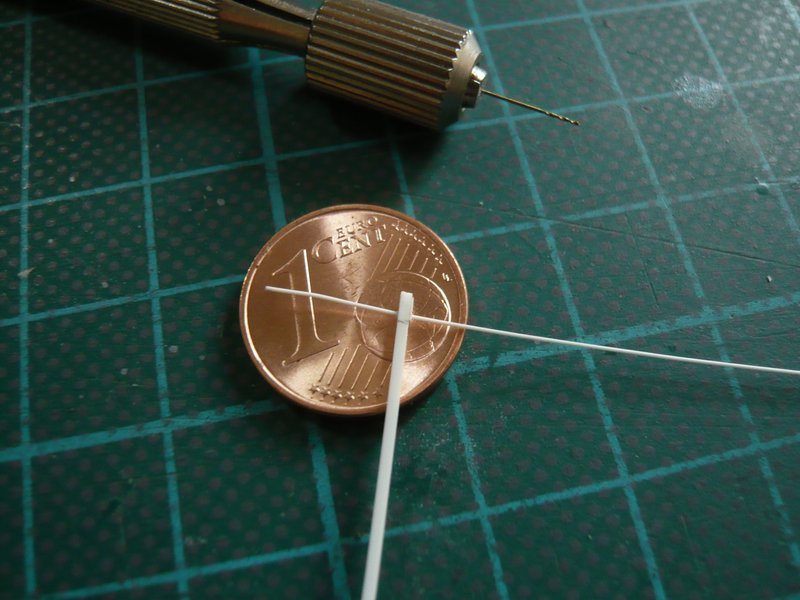
Then the small hole (Ø 0,3 mm) for the bollard foot was drilled and a 0,3 mm round profile like a thread was threaded through a needle eye. And in order to look more like a bollard, then I have glued at the end a thin disc from a 0,4 mm round profile. But to get this centrally was then again a true patience game and has worked only after several attempts.

After adjustment of the overhang, the bollard was glued with MEK,
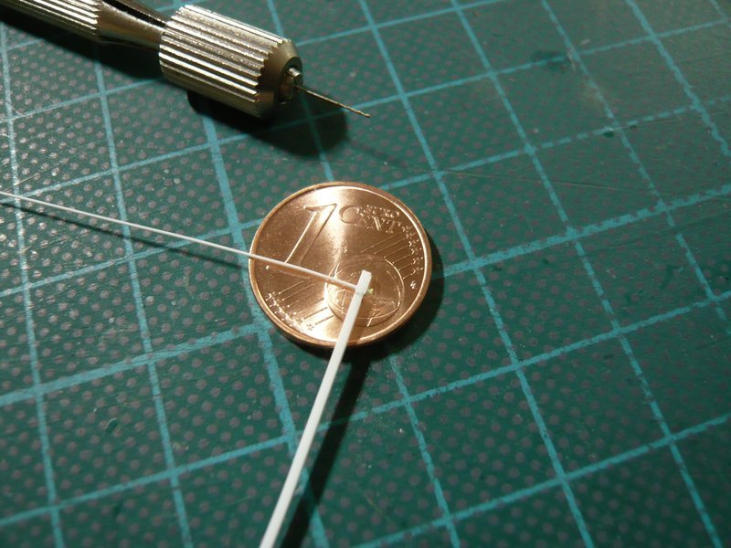
and then the rest on the underside was cut off. And finally, a thin disc (Ø 0,4 mm) was glued on as locking screw,

what can be seen somewhat better from the side.

Here one can see the comparison with the first prototype,
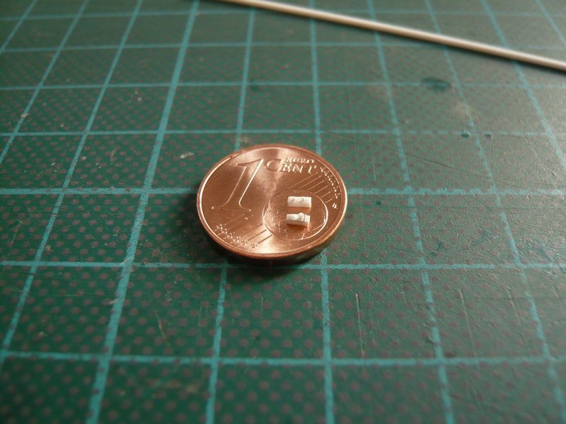
and in the meantime, the second fixing rail has also been completed so that the assembly can now follow.

However, previously comes the test fitting and alignment of the two parts on the inlet pipe, but whose macro-images are relatively indistinct due to the too low contrast differences of white/white objects.

At even smaller distance the autofocus of my Digicam however is unfortunately at the end.

These details will become clearer only in the painted state, and as long as I have unfortunately to console you.

Maybe I can present even better shots.

After the holding rail and the guide roller are now also glued and can no longer fly away, today still a few better pics have succeeded to me,
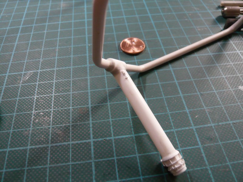
on which the details come out more clearly.
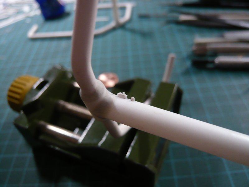
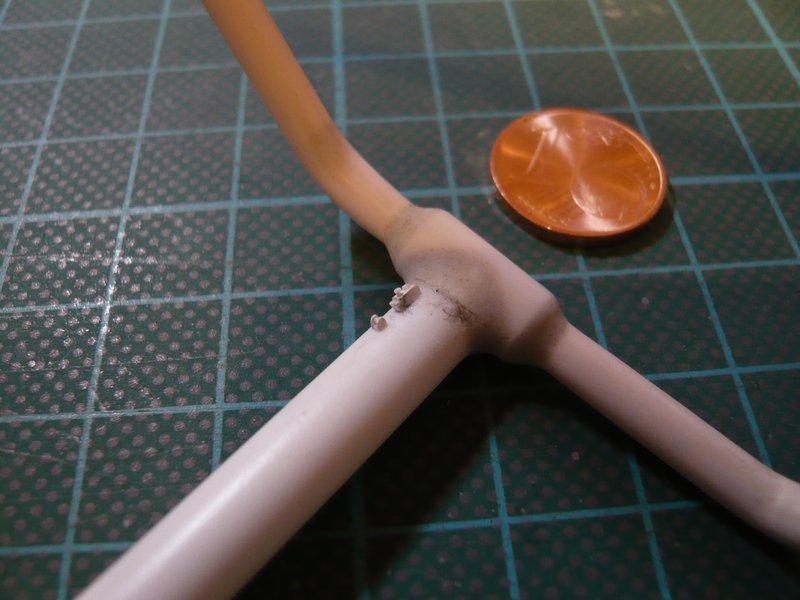
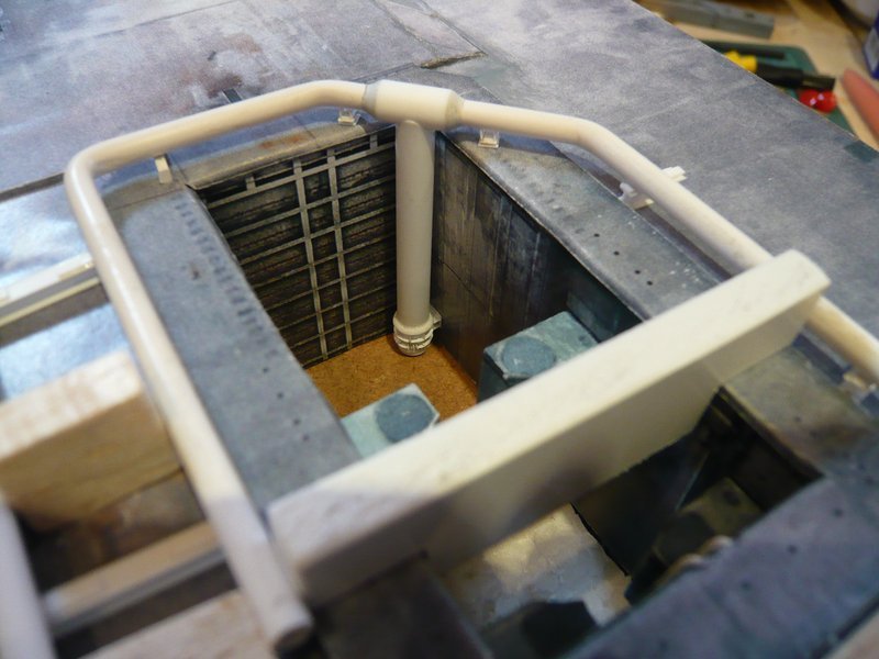
And here finally the first finished inlet pipe in the SRB chamber corner.

Well, the light conditions in such images are often crucial.

3 Likes

Hello Guys,

meanwhile, the other inlet pipe has also got its holding rail and the guide roller.

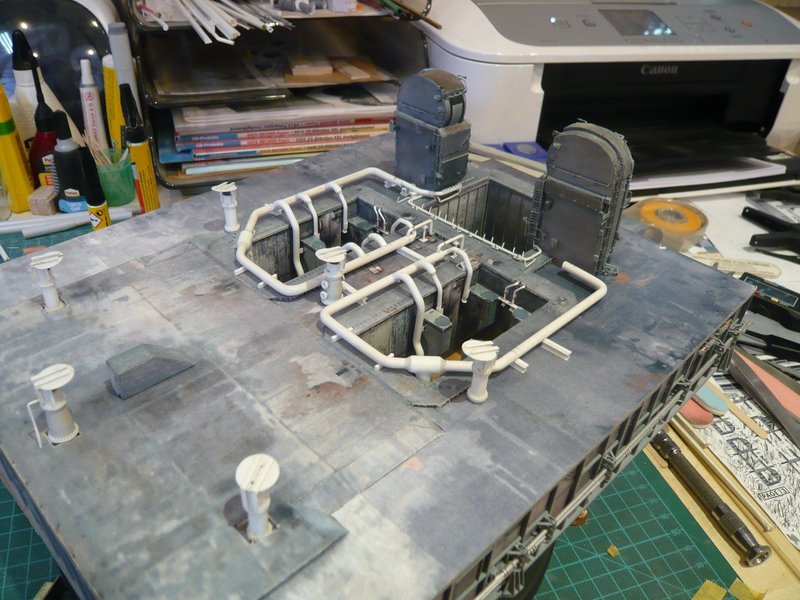
And for stimulation of the last rather dreary test fitting sceneries, I have again arranged the nice Rainbirds, which the picture are rounding off a bit again.

But this by no means should not distract from the supply pipes and their details, although now you only see that there is something on the top, but without being able to recognize it with the naked eye.

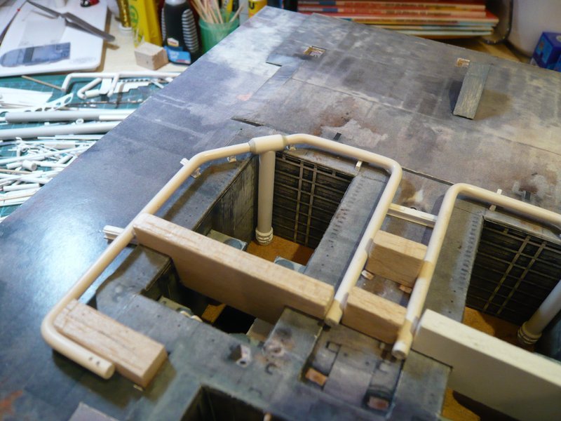
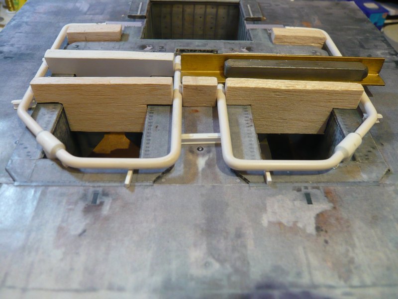
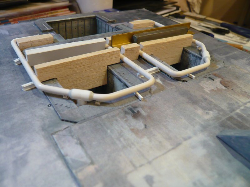
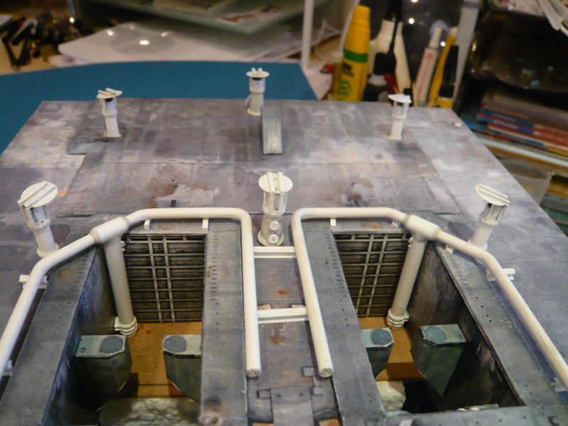
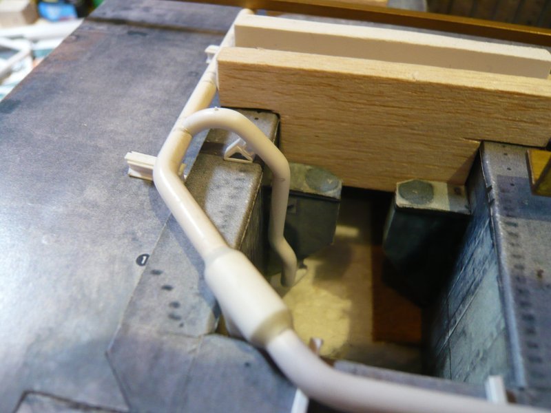
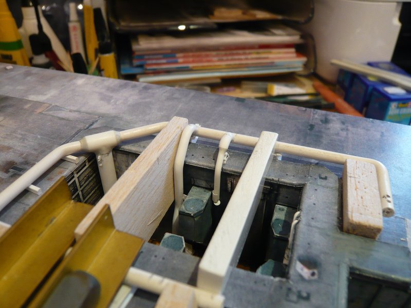
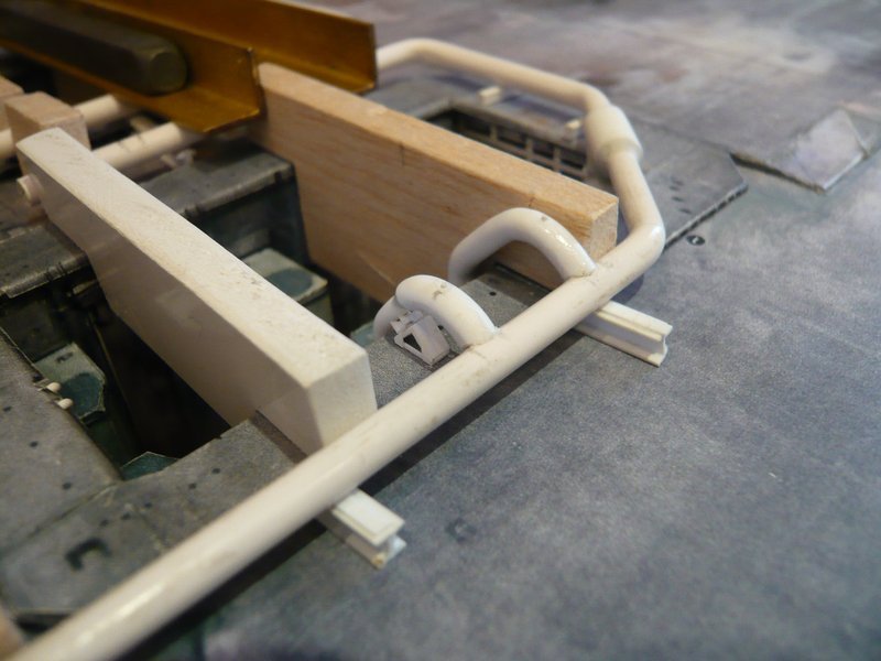
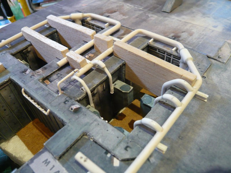
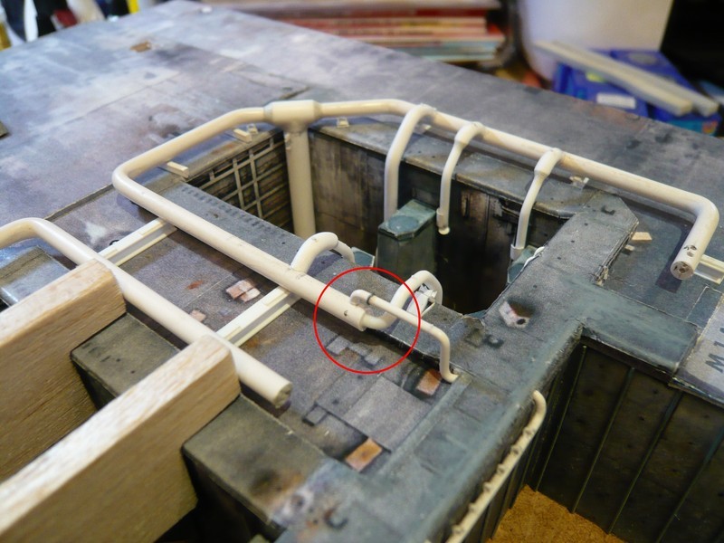
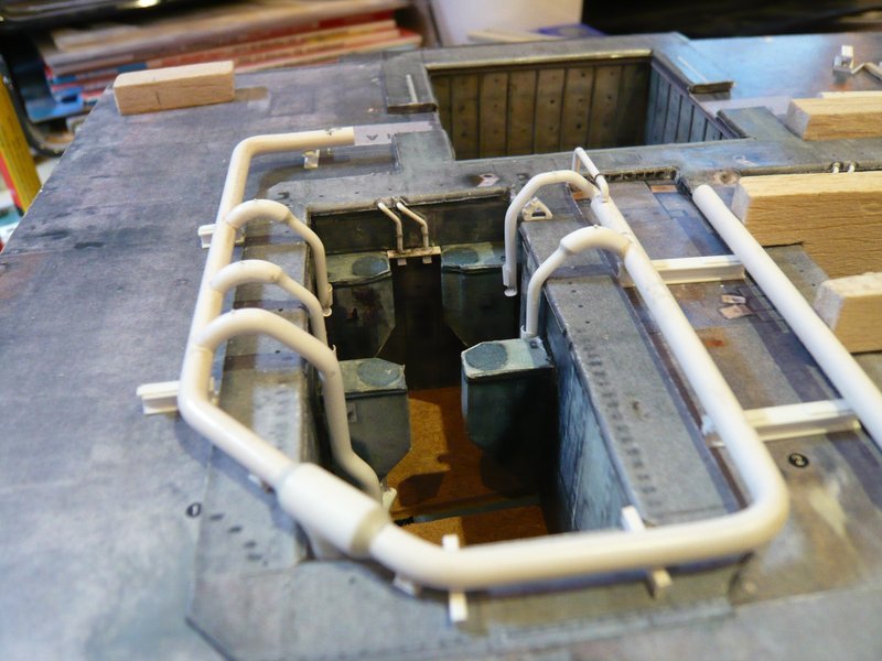
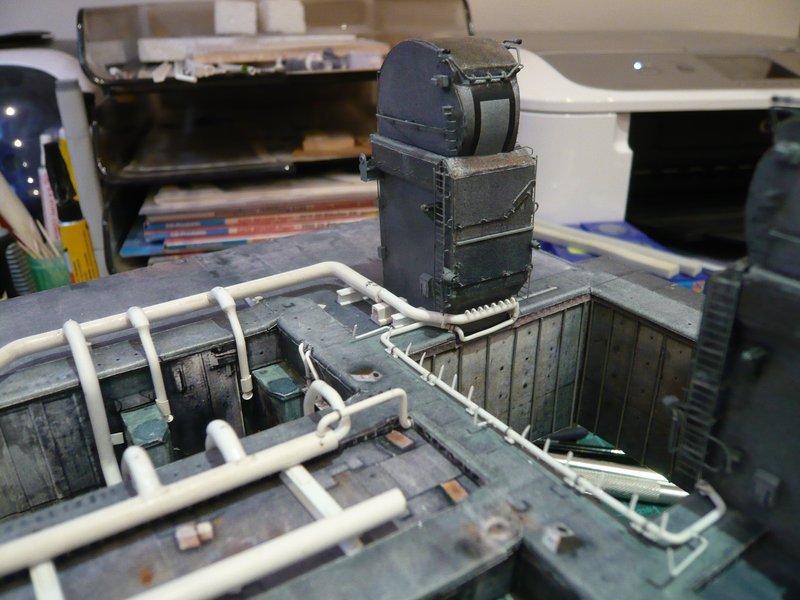
And then I have glued the first of the four back 18’’ outlets onto the ring line, which had to be back into the Balsa corset so that nothing could slip away until the glue was drying.

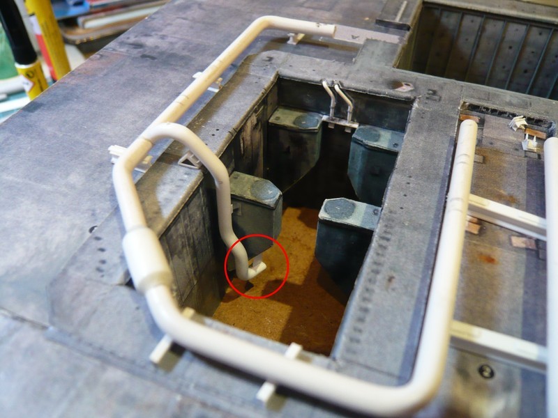
Now I’m curious whether the ring line with the outlet can now be carefully removed out of the shaft, which I hope, or whether this is prevented by the lower support plate under the slope of the SRB support. Because then I would have a problem and would have to come up with a clever idea.

somehow I was apprehensive a bit already, but now it has unfortunately become certainty. Not only the lower support plates under the slantings of the rear SRB-Supports are the hook, but the rear 18’’ outlets per se, what I could have thought however with a more thorough consideration actually before.

The ring line with the outlet can still be removed by moving it somewhat to the right and then pulling it upwards,

but this does not work any more if the other outlet would be glued in the same way onto the inserted ring line.

It basically fails at the inward ends of these rear outlets with the outlet openings together with support plates, which would make the removal of the pipe skeleton impossible. But now I must digest this bitter realization first and breath through a bit.

The case is complicated, but not hopeless, and I already have some ideas, though this would not work again without minor surgery, but thereto later more.

So long and thanks for watching.

1 Like

Hello everybody,

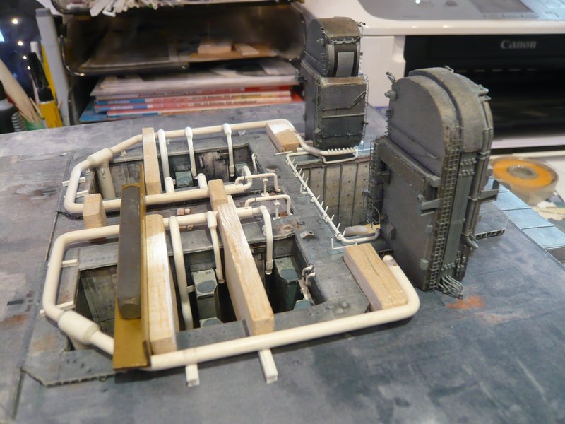
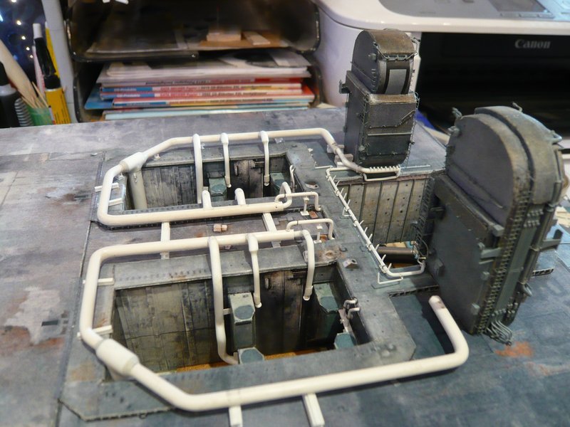
the solution of the problem is also not so easy, because I would like to model the whole pipe skeleton with all outlets also at the transitions with Apoxie Sculpt and would like to install it completely after painting.

And that is why I will change my assembly sequence so far and first glue the four front 18" outlets between the SRB-Supports. Then I would carefully remove the two rear SRB-Supports as at the time when rebuilding the SRB chambers.

Afterwards I would glue the rear outlets with the support plates on the ring line and only finally at the end the two SRB-Supports glue again to the old place and adjust with the existing height stop.

As far as my consideration, which is hitherto only gray theory, but should work in my opinion.

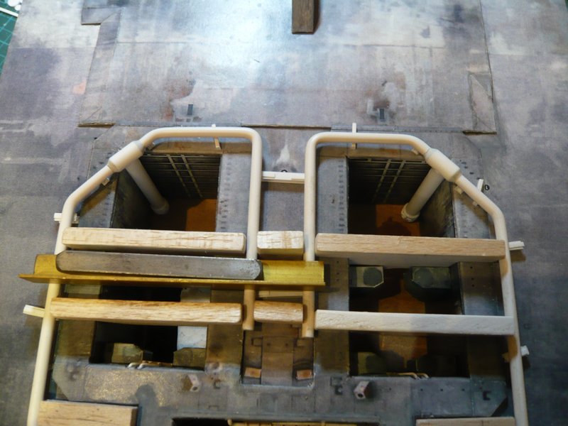
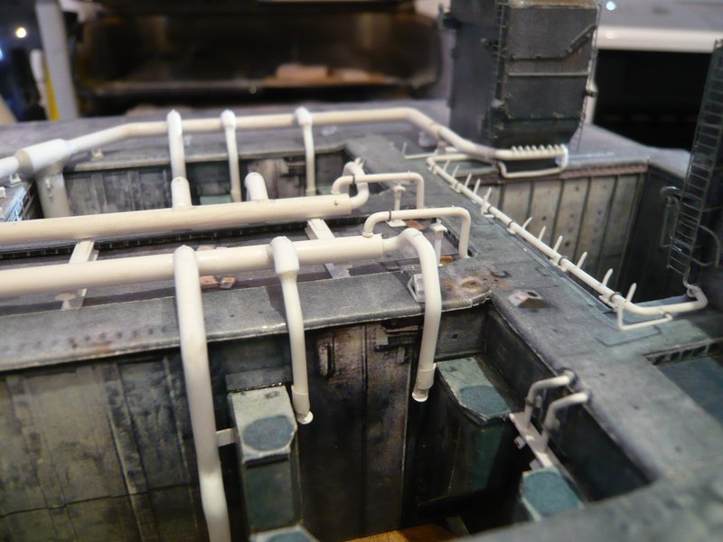
Now I can show a few photos from today’s assembly of the next two front 18’’ outlets with the rejuvenations on 12’’ which sit between the SRB Supports.

As already indicated, I now have either to remove the rear outlet with the support plate for the assembly of the two opposing outlets, or immediately the SRB support.

Wait and see.

2 Likes

Hello together,

I have chosen the last version and the SRB-Supports carefully removed and then attached with double-sided tape as a placeholder for the assembly of the outlets again.

The 9’’ outlet I have not yet glued, because it would otherwise disturb during the modeling of the underlying transition from the ring line to the 12’’ outlet.

Up to now it fits all together quite well.

And next, it can now go on behind the LOX-TSM with the transition from the ring line to the 16’’ extension with the 12’’ nozzle tube.

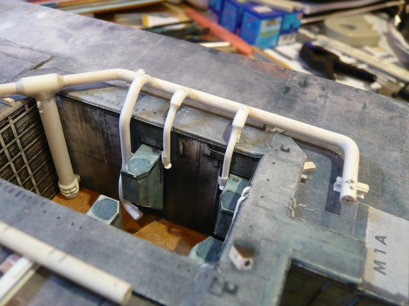
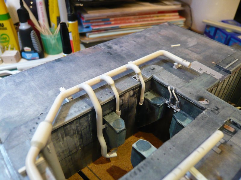
And here is only a short update from the growing pipe skeleton around the left SRB shaft.

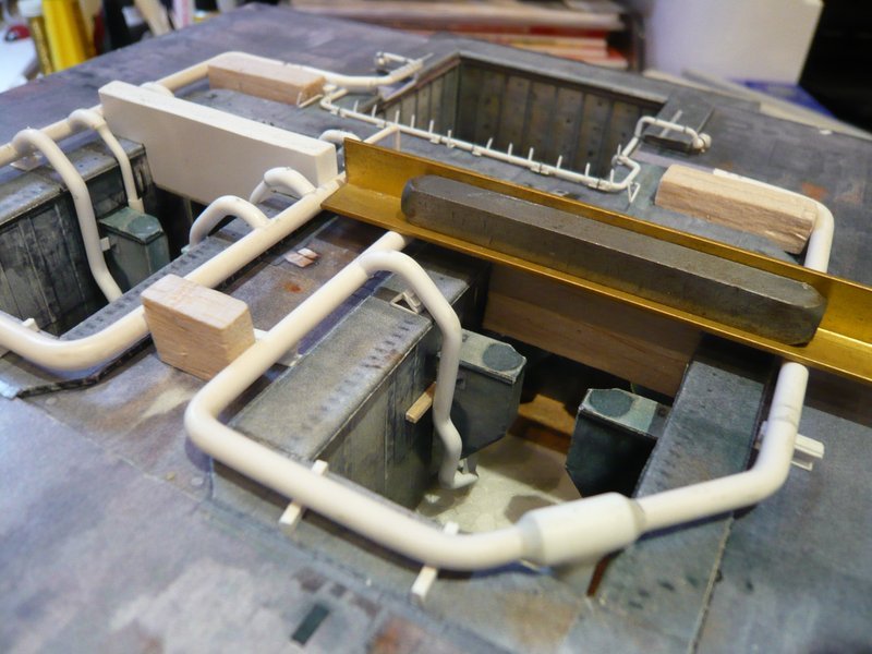
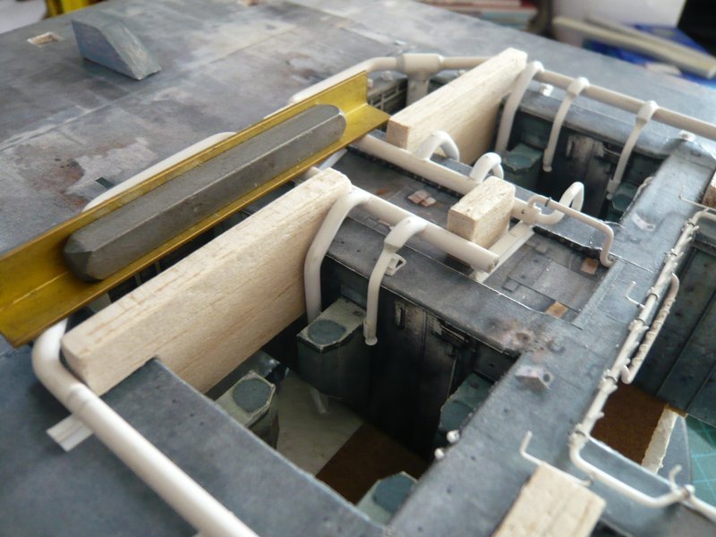
As already announced, the ring line behind the [color=blue]LOX-TSM[/color] was extended by the 16’’ tapering with the subsequent transition to the 12’’ nozzle tube. Again, the precise and, above all, stable position of the ring line is important, for which purpose the line was again weighed down in a proven way with a weight.
After the alignment of the nozzle pipe under the TSM the extended pipe was glued to the end of the ring line with MEK.

And even after removal of the weight, everything was still stable.

Now only the already prepared two small 6’’ outlets still have to be glued on the ring line, which lead into the SRB chamber, then the first ring line would be complete.

That’s it for today.

1 Like

Hello everybody,

oh no, this was unfortunately too briefly thought.

The two small 6’’ outlets can not yet be glued as long as I still need the space behind the TSMs for the Balsa spacers in the corners to fix the position of the ring lines, in order to also to be able to mount the outlets on the other ring line in a stable position.

At first, the rear 18’’ outlet was glued with the two support plates. However, at that I was not aware that this time I had begun on the inside, and with that on the wrong side, but what was to become apparent only later.
So it went on with the two outlets between the SRB-Supports.
The two 9’’ transitions are again only placed on and the small supports are only supported underneath.

And as one can see, even after taking away the spacers and weights, everything still fits together well and looks quite well.

And the total view with the flock of birds also looks like cool.
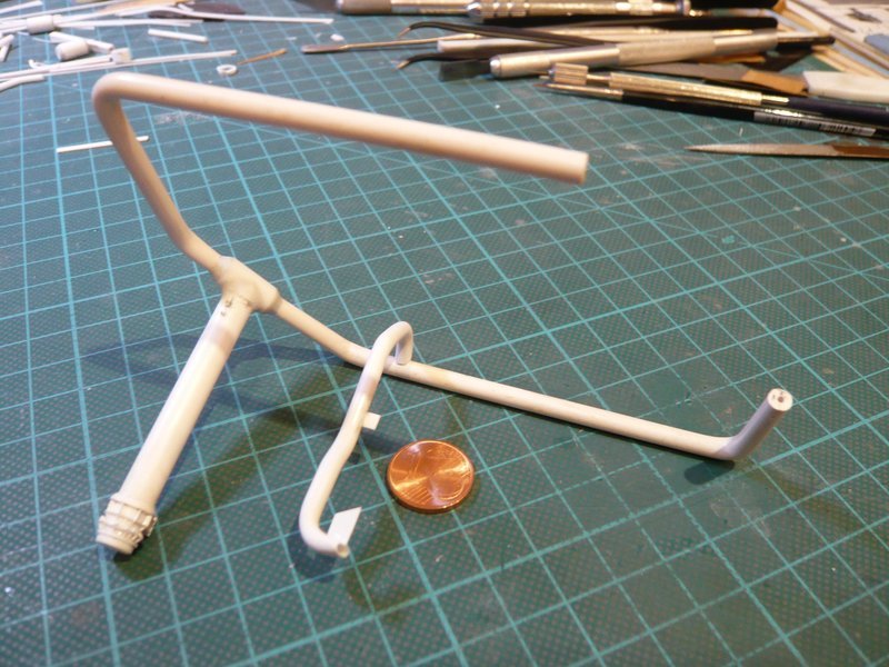
But when I wanted to extract the pipe skeleton, the shocking realization came that I had begun on the wrong side. Now the skeleton was blocked inwards by the three outlets and outwards through theinlet pipe in the shaft corner.

But with the utmost caution and the necessary sensitivity, I then managed to move the rear outlet with the support plate around the SRB support.

Now I can again carefully remove the two SRB-Supports, in order to be able to mount the three external outlets on the inserted skeleton.

5 Likes

Simply mind blowing work. All those pipe mounting make for a complex structure. Interesting thing through this all is your doing this in the old school fashion. A lot of elbow grease at work.:wink:

Make sure you are lubricant to keep going smoothly :laughing:

1 Like

Thanks Mike for your nice compliment.

In retrospect, the Sound Suppression Water System (SSWS) was the most complicated chapter of my project, which you haven’t seen all of yet, which is why the show must go on.

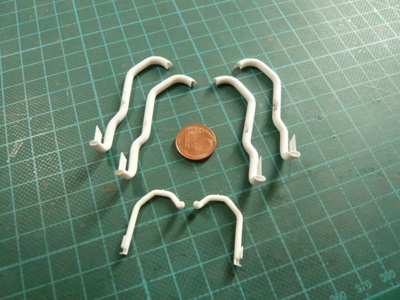
Just the reproducible bending of these crazy pipes was an immense challenge that took a lot of skill, patience and sweat.

Presumably the latter was my lubricant.

Hi friends,

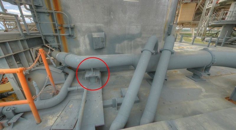
before I mount the remaining three outer outlets on the ring line behind the LH2-TSM, I’ve ever thought about the further procedure. There is also the assembly of the many Pipe Supports to consider, on which the two ring lines as well as the twelve exits sit.

At that one has to distinguish between the supports of the ring lines, of which there are supports with and without a clamping ring, and those under the outlets, which have no clamping rings.

And since that all is difficult to distinguish between them, I have once again counted thoroughly and all supports marked in a new image.

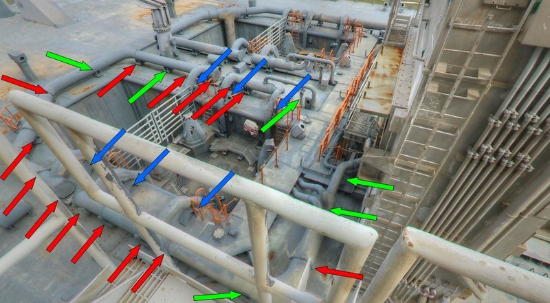
But just do not be frightened please, I want to explain it immediately at one ring line by using colored arrows. It is unfortunately rather a plan view, but on this image all supports are to see, or maybe only to guess, sorry.


Source: NASA

There are first the six small triangular supports (blue) at the outlets, of which I have to make five more, so overall still 11.


Source: nasatech.net

And then there are a total of 20 outlets on each ring line, when I also keep count the high slender support under the 9’’ outlet.

While the ring line have clamping rings at the 14 red-marked supports, they are missing from the remaining six green-marked supports. Accordingly there are respectively 26 supports on both ring lines, in total therefore 52.


Source: nasatech.net

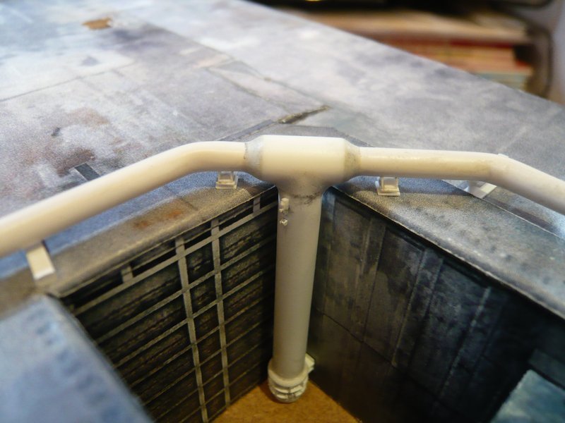
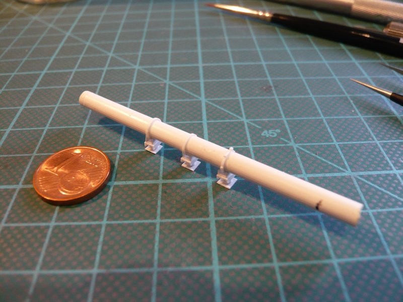
For the further assembly, I must now note that I must first attach the clamping rings at the places of the ring line, where the supports are sitting, and only after that, the supports can be glued at the ring line and finally painted all together.

In order to demonstrate this already at the model, at first I have marked the support positions at the ring line and then arranged all my previous supports, whereby I have now unfortunately forgotten the support under the 9’’ outlet.

In addition to the still missing 11 triangular supports under the outlets, I also still need two of these simple supports here, which are standing behind the TSMs on the SRB Blast Shields.


Source: nasatech.net

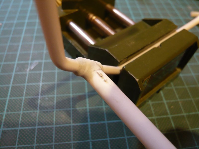
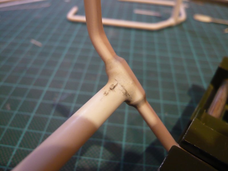
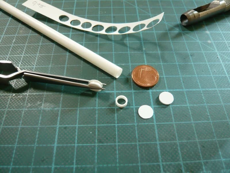
And in the case of the clamping rings we were already so far some time ago,

whereby for the favored right clamping ring only the manufacturing technique would have to be optimized, but for what I already have an idea.

That’s what it should have been for today and thanks for watching.

1 Like

Already this project has risen to about 5 in my imaginary All-time Top-10 Scratch-builds chart, and I’m sure the only way from here is higher. Frightening and brilliant work Manfred.

I’m was wondering about your painting plans – so am I right to understand all white pipework is not glued down yet?

1 Like