Space Shuttle Launch Complex 39A with Challenger STS-6 (1:144)

Thank you Tim for appreciating my previous work and also for your ranking so far after just under 5.000 viewings.

Then there is still a lot of room for improvement!

Where will I be then when we will have broken the 1 Million Views sound barrier here?
Maybe in orbit …

BTW, the two SSWS Ring lines must first be completed before they can be painted by Airbrush. And only then they are finally glued around the SRB Exhaust Chambers.

So you’ll have to be patient a little longer, don’t panic. Stay tuned and you will see it.

2 Likes

Hello everybody,

but always nice in sequence.

Today, I got to work on the last two remaining Pipe Supports below the 16’’ extensions (Ø 2,5 mm) of the ring lines in front of (respectively behind) the TSMs.

As can be seen from the photo already shown, the supports are similar in construction to the 24’’ ring line (Ø 4,0 mm), but they are somewhat smaller and have only one sickle for holding the pipe (Ø 2,5 mm).

In the dimensioning of the support and its individual parts, the clear height under the tube of 2,5 mm was decisive. Since for this smaller support the Evergreen U-profile (2,5 mm) appeared for me too clunky, I have it this time scratched from 0,25 x 2 mm and 0,25 x 0,75 mm strips.

The tiny sickles are punched (Ø 2 mm) and have a web height of approx. 0,5 mm.
Since the initially provided foot parts resulted in a somewhat too high construction,

I went back again to smaller beads and discs.

After the substructure was glued,

the tiny sickle was glued,

and the first of the two supports was finished.

And then I finally could exchange the previous dummy and replace with the new support, which fits well with its height under the tube.

Now I have still to clone this support only, what you can see here.

The second time everything is already somewhat easier, especially since the individual parts were already prepared. Merely the handling of the individual parts of these midgets is not easy, because even holding in the tweezers is not harmless, since they can easily jump away, therefore Safety first!

But if one clamp the U-profile between two rulers, this works quite well. And the small rod to thread the individual parts is, of course, absolutely helpful and therefore indispensable.

The gluing of the mini-sickle is then again the crowning conclusion. And now the umbilical stick can be separated off.

Thereby the couple is completed.

And now it can go on with the missing outlets on the other ring line.

1 Like

What is also amazing about this engineering extravaganza is it achieves the same unwavering consistency in attention to detail in every update. No small detail is forgotten or left out … It’s just amazing really…

Thanks John for your extravagant compliment.

As I see you follow each update really closely, which is amazing and shows me that you also seem to enjoy these details.

Then we will still have a lot of fun together …

1 Like

Hello friends,

after the dismantling and re-mantling of the SRB-Supports, the three outer outlets were mounted on the right-hand ring line.

At it the bend of the rear outlet had to be adjusted somewhat, because it was a bit too long.

The next outlet has then fitted again right away.

And also the front outlet had to be modified several times, until it finally has fitted and I could give him my blessing.

Tomorrow it will go around the corner to the extension of the ring line with the transition to the Nozzle pipe behind the LH2-TSM.

2 Likes

Hi there,

so, then I want to bring the extension of the ring line with the nozzle tube around the corner.

When looking at some NASAtech.net panoramas, I suddenly noticed again this clamping ring on the extension, which I had actually forgotten on the other side and now has to be installed later.


Source: nasatech.net

It is, of course, easier to mount the extension if it is not yet glued to the ring line. And so I did this, whereby I used Lead wire (Ø 0,4 mm), which I have glued with MEK, yup, with MEK!!!

And that actually works whether you believe it, or not. This astonishing effect I had noticed several times unpleasantly when gluing Styrene parts on a sheet metal underlay, which suddenly suddenly stuck to the underlay. And this side effect benefited me this time, especially since the clamping ring has nothing great to resist.

And here the extension is already glued and fits well around the corner of the TSM dummy.

This must now harden in a stable position before going on.

Since the time for drying was more than sufficient, it went on now.

It had still been missing the two remaining 6’’ outlts on the ring line behind the LH2-TSM, which got their nipples again,

and then their clamping rings.

And the thickenings at the foot points I have also indicated by rings.

Then the two outlets were glued behind the LH2-TSM with MEK. To get the same clearance height, I have used a 2 mm rod as a spacer.

Then followed the installation of the outlets on the other side behind the LOX-TSM.

And without the annoying Balsa stabilizers it looks much more friendly.

Therewith now all the pipes of the SSWS are finished and almost completely installed.

Now I can calmly turn to the remaining 11 Triangular supports at the outlets.

Then both ring lines skeletons have to be removed again and all the transitions must be modeled with Apoxie Sculpt again, whereby I’m scared a bit when I imagine that action in detail …

And then follows the exciting chapter Clamping rings.

But before the Ring line skeletons are now removed again, I have set free the wild flock of Rainbirds once again, their tricky scratch-building an extra chapter is dedicated.

I always like to look at them again and again.

2 Likes

Hello everybody,

at first, I fixed the crescent-shaped supports for the three missing rear 18" outlets (Ø 3,2 mm) in a tried and tested manner between two steel rulers and glued with MEK,

but then laid aside.

In the meantime, I had once again looked at the supports of all the outlets on the MLP-2, because they have differently shaped stiffening points, at which I had already pointed out previously.

This image, however, belongs to the MLP-3 and is therefore not relevant to me,


Source: nasatech.net

because this support at the MLP-2 looks like this and has both at the rear,


Source: nasatech.net

as well as at the front, three such stiffening corners, as can be seen.


Source: NASA Street View

Admittedly, these are all very difficile detail differences, but I’m taking it a bit more precisely, as you know.

That is why we remain at this support, which I have so far completed as first and used for the test fitting of the outlets. However, it had so far only the two lower triangles on the front (to the LOX-TSM), and now I have glued also the three triangles on the back.

Now only the upper triangle on the front was missing,

which I have attached now, and with which this support would now be complete.

This was followed by gluing of the filigree frame (0,25 mm x 0,5 mm) for the next support, whereby I initially wanted to go back to my previous gluing and bending technique,

but which annoyed me as much as the first time, wherefore I have rejected it, because the corners are not bent exactly enough.

Therefore, I have considered the following technique, which initially looks somewhat inconvenient, but ultimately provides better results.

For this purpose I have glued strips 0,5 mm x 0,5 mm under the two undersides of the angle with a little overhang, between which I have glued matching strips 0,25 mm x 0,5 mm, everything again with MEK, which has worked well for these minimal gluing.

And after the overhangs had been separated, I had this small but fine roof with beautiful square frame edges.

So far for today.

2 Likes

Hello my friends,

here’s a little journey back in time to the past of my work … to relax and distract you from the stress of all these tiny parts.

It was Christmas 2016 (12/25/2016 08:17 pm), and that’s why I also celebrated Christmas on the MLP back then, as one can see on the true to scale treelet (approx. 15 mm), which would range only up to the upper “cartridge belt” of the Rainbirds.

To make the size comparison even more vivid, here it is again for the fun of it: Merry Christmas with Andrew Scheer.

1 Like

Hello everybody,

in order to prevent possible withdrawal symptoms, I have continued with the still missing supports for the rear 18’’ outlets and attached their frames first and then the tiny stiffening corners.

In the upper row lay the two supports of the outlets behind the LOX-TSM, and below the supports behind the LH2-TSM. After the right support was already finished, now also the last support got his four corners.

On these images, the different arrangement of the stiffening corners can be compared once again, first at the outlets behind the LOX-TSM, which are identical on the front and back, both in their number and in shape.


Source: nasatech.net

While the arrangement of the corners of the outlets behind the LH2-TSM on the rear side is identical with the corners behind the LOX-TSM,


Source: nasatech.net

the upper triangle is missing on the front of the outer support, as can be seen in this image.


Source: nasatech.net

But exceptions famously confirm the rule.

Then I have glued the crescent-shaped pipe holders.

And this is how the test fitting of the supports looks at the MLP.

Now I can turn to the eight supports for the 12’’ outlets, which is why I have used again my Punch & Die Set.

In order to obtain the same web widths at least on one side at the lower curve, I have attached a stop with a distance of 1 mm from the stamp,

which has worked well again.

After that, the sickles were cut off with the cutter chisel.

Then I have glued the angles on both sides onto the frame profiles (0,5 mm x 0,5 mm).

and then separated.

So far, so good, but stop! Have you noticed something?

Okay, me also not so far. But suddenly, when I did count the roofs, I always came only up to seven, although there must be eight supports.

So my first glance went intuitively on the floor again, but there was nothing to be seen.

Oh no, not again, I thought to myself, and began to look at the table in front of me, which is not so simple, because there lies much too much stuff around.

And lo and behold, at the edge of the cutting waste I saw the 8th angle lying next to two other angles, which were however somewhat too narrow, and so I was jolly glad.

All’s well that ends well, and so I can go on tomorrow.

5 Likes

Hello everybody,

today I want to quickly report myself with the last images of these supports.

Since the procedures are meanwhile well-known, I can make it short and let the images speak for themselves.

The gluing of the sickles was again such a tricky business, some had unglued from the strip and were glued tight only in the second run.

Now I want to show you the last Supports with their tiny stabilization corners.

At it an extra calm hand and a lot of patience were asked, which has now become a routine in this area of dimensions. And the headset magnifier and a pointed tweezers were of course also part of the standard tools again.

And since for gluing of the corners a stable position of the unwieldy roofs is indispensable, I have reflected about a special jig for today’s support finale.

For this I have squeezed the angles into a corset of three steel rulers, which I have clamped with small Supermagnets (NdFeB) on a sheet metal. This allows to glue the strips without overhang with the 45° slant directly onto the angle and still position it when using a simple Styrene glue.

And so one could let yet a few tenths space up to the upper margin, because the stabilization corners do not close directly with the angle edge, as one can see in this image. But later on this will hardly to be seen with the naked eye any more.


Source: nasatech.net

And after the same procedure on the back side,

and trimming off the lower overhangs, the first of the eight supports is already finished and looks well.

But there are also supports with some other stabilization corners, as one can see here at one of the front outlets behind the TSMs.


Source: nasatech.net

And these corners were made according to the same pattern, first on the front,

and then on the back side.

And now all eight supports have been finished so far, because now only the sickle holders have to be glued.

In the upper row one can see the front supports of the outlets behind the TSMs and below it the middle supports behind the SRB supports.

And an exception in this image confirms once again the several times stressed rule, but perhaps it won’t be even noticeable.

And so we’re back in business.

1 Like

Hello everybody,

so friends, it is so far, now all 12 supports for the front outlets are finished, and I can once again breath deeply, because I often had to hold my breath during handling the treacherous midgets in the tweezers to glue the gusset plates and fragile sickle holders.

Now, here are the six supports behind the LOX-TSM, and on the right the six behind the LH2-TSM.

The next step was the test fitting of these 12 supports together with all the other supports of the SSWS, i.e. total of 52, which now gives an imposing image.

And to round off the picture, I have also added the six Rainbirds again.

I am always amazed again, when I see this coole SSWS, truly a monster Labyrinth.

With the gluing of the supports on the two ring lines, I have to wait however still something, because before the clamping rings have still to be attached, because afterwards would certainly be a little too stressful.

And these clamping rings want to be produced first, what will be again a tricky fiddling, whereby I want to use this time a smarter technique, which I have mentioned before.

3 Likes

2 Likes

What a nice joke, a dog named Mike …

This pretty picture speaks volumes, as I see, and tells me that you are just as amazed and stunned as your little deputy, as if to say: That’s defenitely jaw-dropping!

But you don’t see a Fata Morgana, just the SSWS on a scale of 1:160.

Hello everybody,

well, then let’s go to the Clamping rings, there is no way to avoid it.

After I had read again in my building report from the midyear of 2015, I once again checked the different shapes of the screw connections of all clamping rings on the MLP-2.

While the majority of the clamping rings are made up of six bolted ring segments, as shown on the right, there are also some, which consist of only four segments (on the left).


Source: nasatech.net

In this panorama image one can recognize the differences from a different perspective very well, and as one can see, the screw connections of the four-part clamping rings are somewhat longer than those of the six-part clamping rings.


Source: nasatech.net

And with the aid of this image, I had already determined the dimensions of the clamping rings and screw connections in those days, whereby the diameter of the 24" pipe (4 mm) was used as reference.


Source: nasatech.net

Since the image of my stock taking at the time seems to me to be somewhat overloaded from today’s point of view,

I have once again shown the number of screw connections of all clamping rings of both ring lines separately. In this case, the red arrows indicate the position of the supports, at which there are no clamping rings.

Here first for the relations at the ring line behind the LH2-TSM,

and here at the ring line behind the LOX-TSM.

As one can see, the type of the clamping rings and the number of their screw connections is not identical on both sides.

After checking the dimensions again, I will use Evergreen Strips (0,38 mm x 0,5 mm) for the six-part clamping rings and for the screw connections strips (0,25 mm x 0,75 mm), where 0,75 mm corresponds to the length of the screw connections. And for the somewhat longer screw connections of the four-part clamping rings I will probably use strips (0,25 mm x 1 mm).

The construction of the clamping rings should be carried out accordingly to the Lattice technique, which I have considered at the time.

For this I first marked the distances of the screw connections on the peripheral length of both types, left for the four-part clamping rings and right for the six-part rings.

Thereby the strips (0,25 mm x 0,75 mm) or (0,25 mm x 1 mm) for the screw connections are placed over parallel lying clamping ring strips (0,38 mm × 0,5 mm) and glued by using MEK, which were then subsequently separated.

So far as the theory, next time prototypes of both types of clamping rings are to follow.

1 Like

Hello folks,

before I can start with the small series production, I have tried the first two prototypes of the clamping rings first without using the lattice technique, in order to see whether or how well the lengths and distances resulting from my templates will be okay.

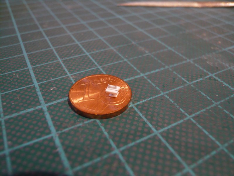
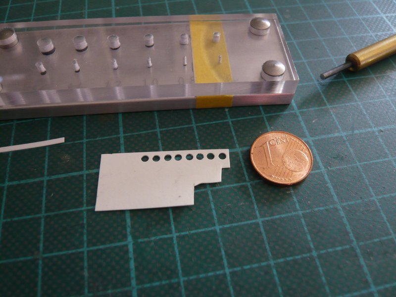
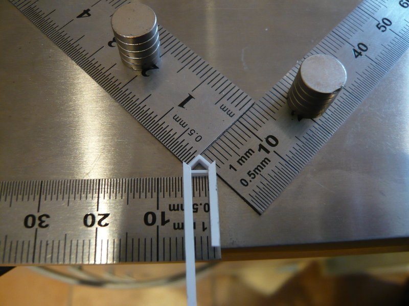
For this purpose, the four strips for the screw connections were positioned on the clamping ring strip (0,38 mm x 0,5 mm) and gently glued with MEK on both sides.

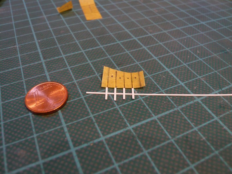
The strips then stuck so tightly that they could easily be cut off on both sides.

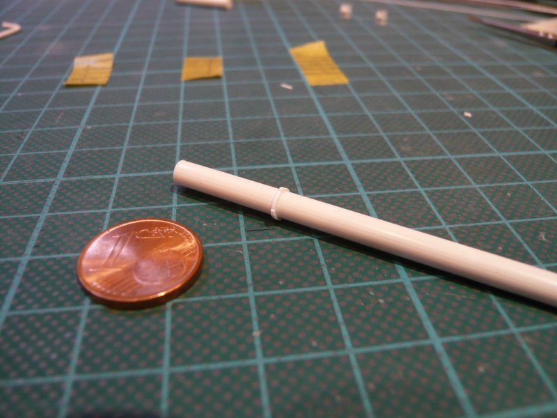
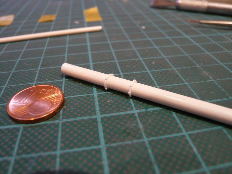
The gluing of the clamping ring on the 4 mm rod took place step by step with CA, because MEK is not suitable for this, which I had to observe unfortunately at that time, and I did not want to make the same disastrous mistake again.

But only after I finished with this four-part clamping ring, it occurred to me that I had not used the wider strip (0,25 mm x 1 mm) for the screw connections, but the narrower (0,25 mm x 0,75 mm) for the six-part clamping rings. But no matter, I have still noticed it in time.

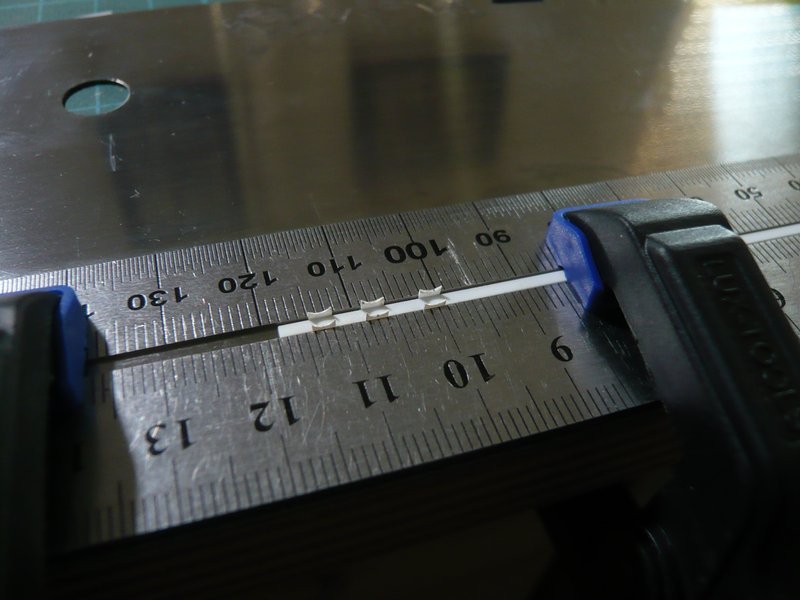
After the same procedure, the six-part clamping ring was built, in which the screwing strips have moved closer together.

This time, too, everything went smoothly with the gluing of the strips,

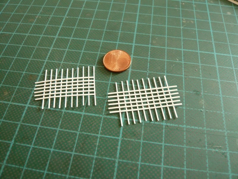
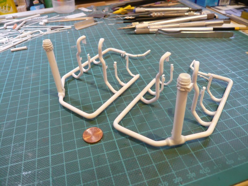
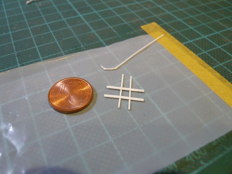
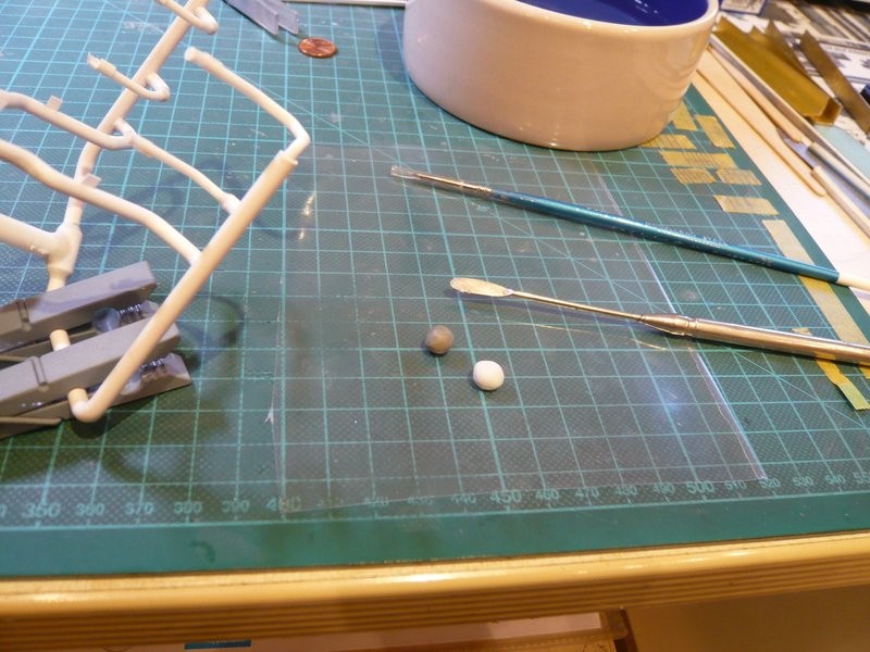
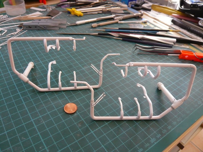
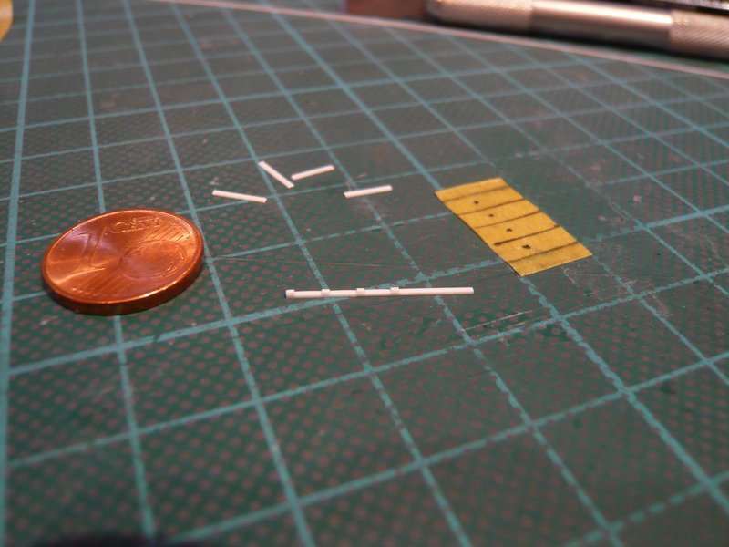
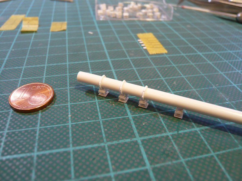
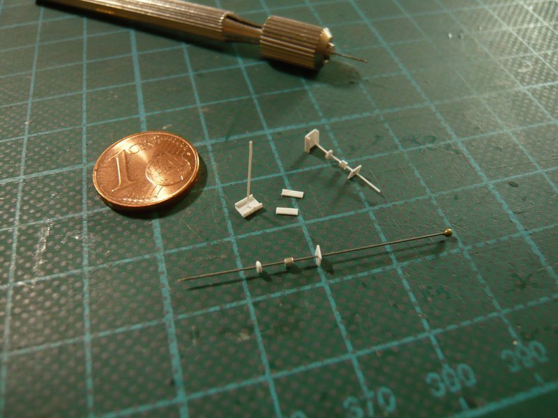
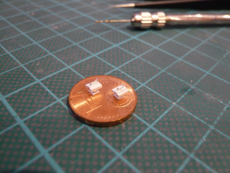
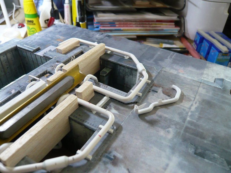
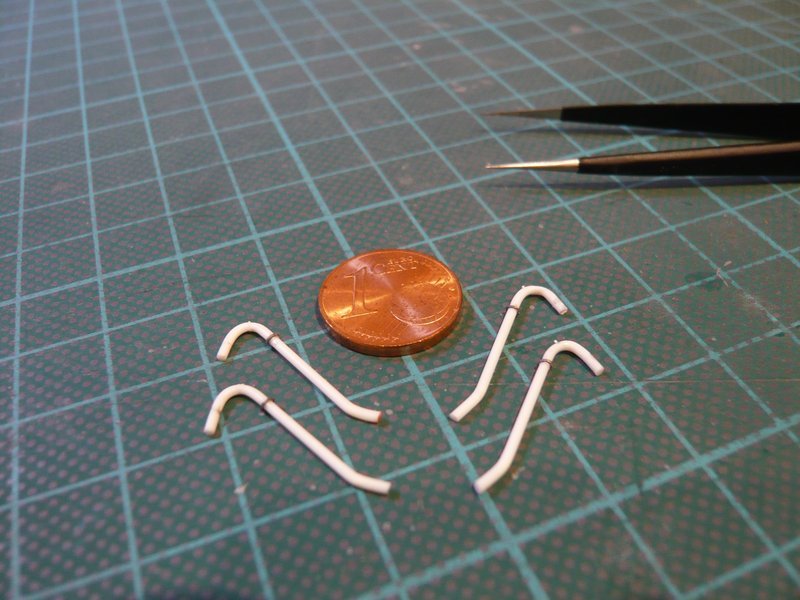
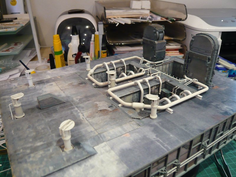
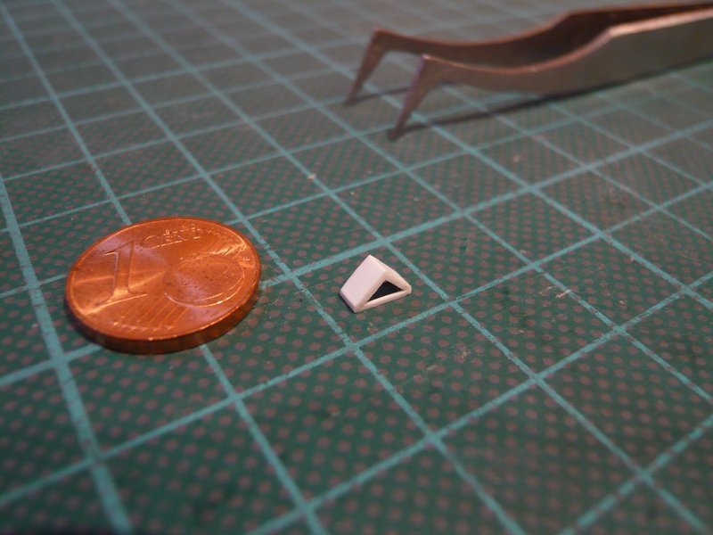
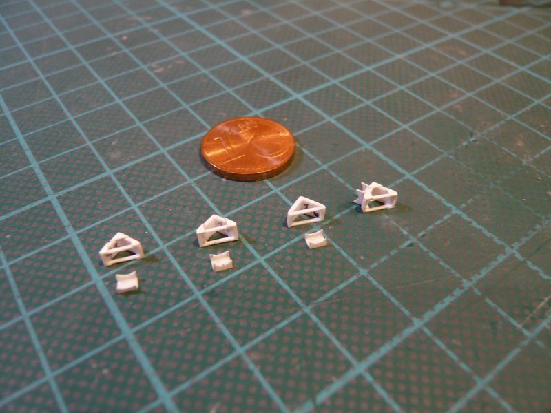
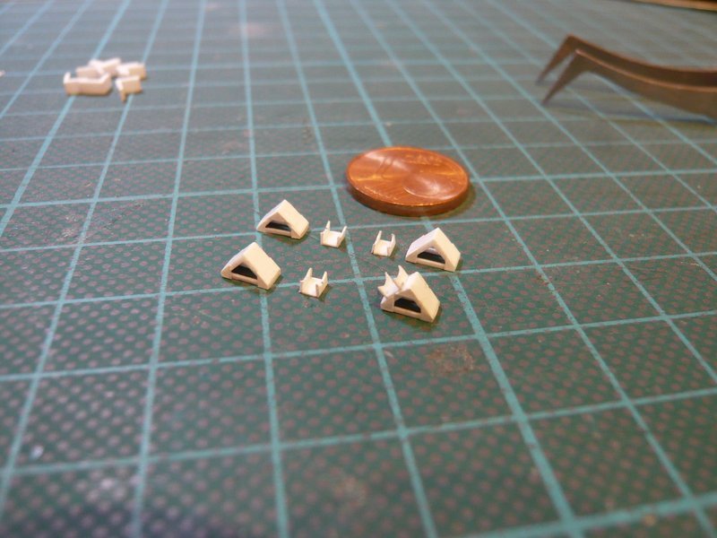
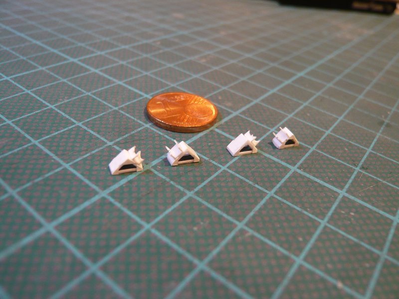
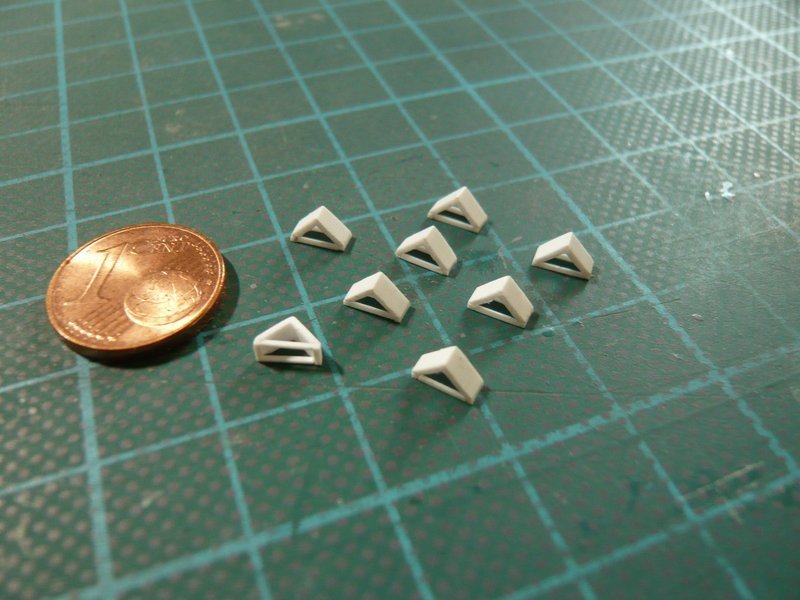
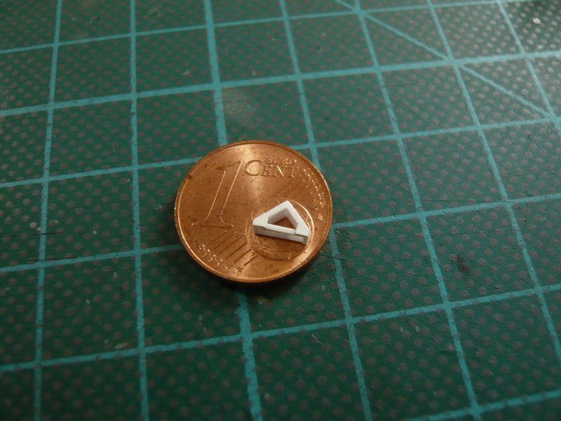
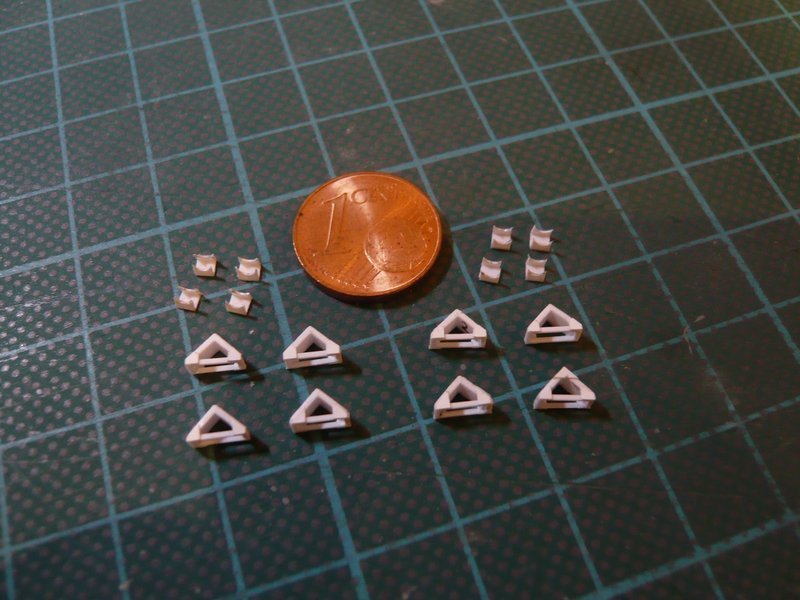
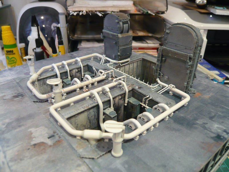
and here one can see both clamping rings next to each other.

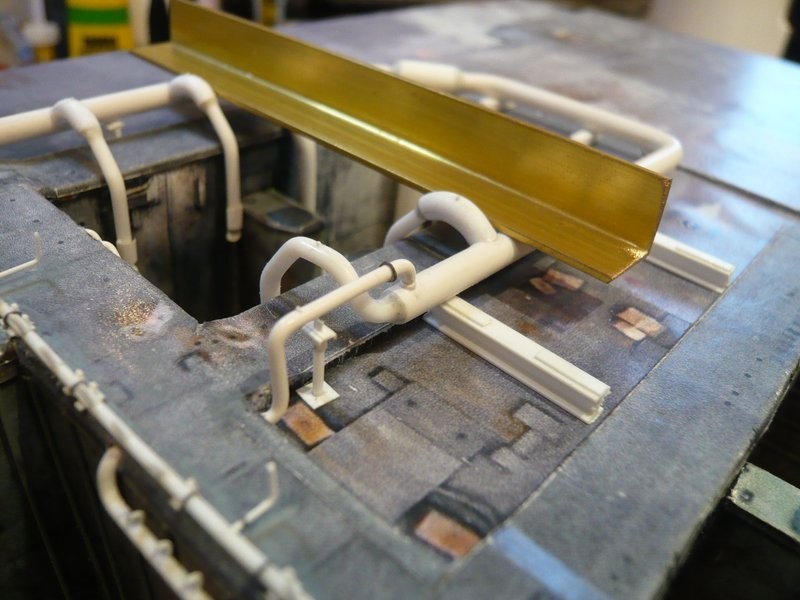
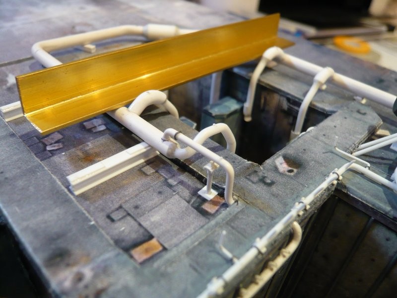
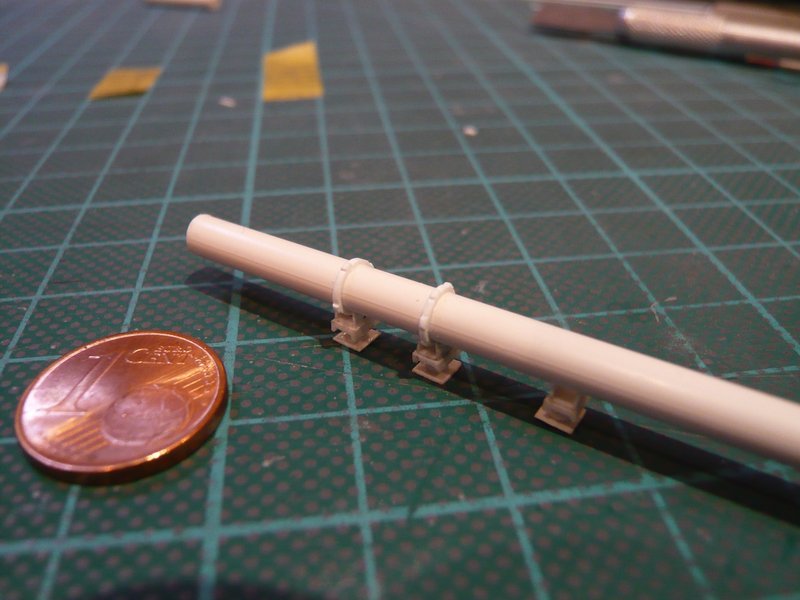
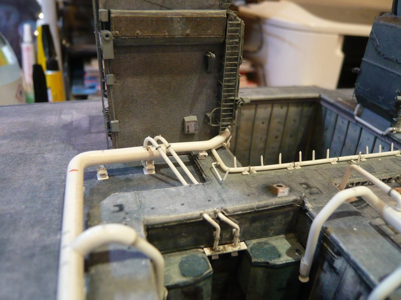
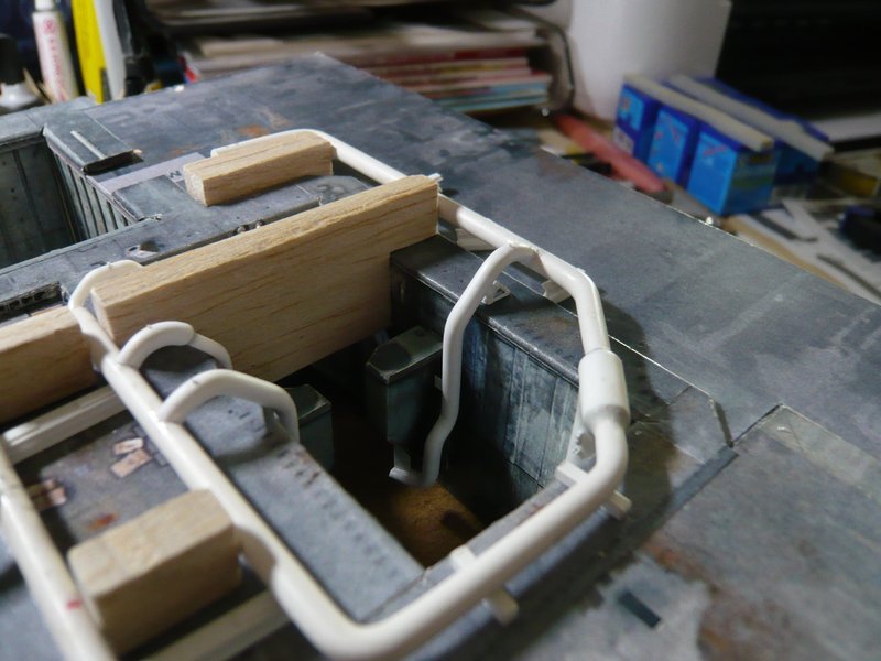
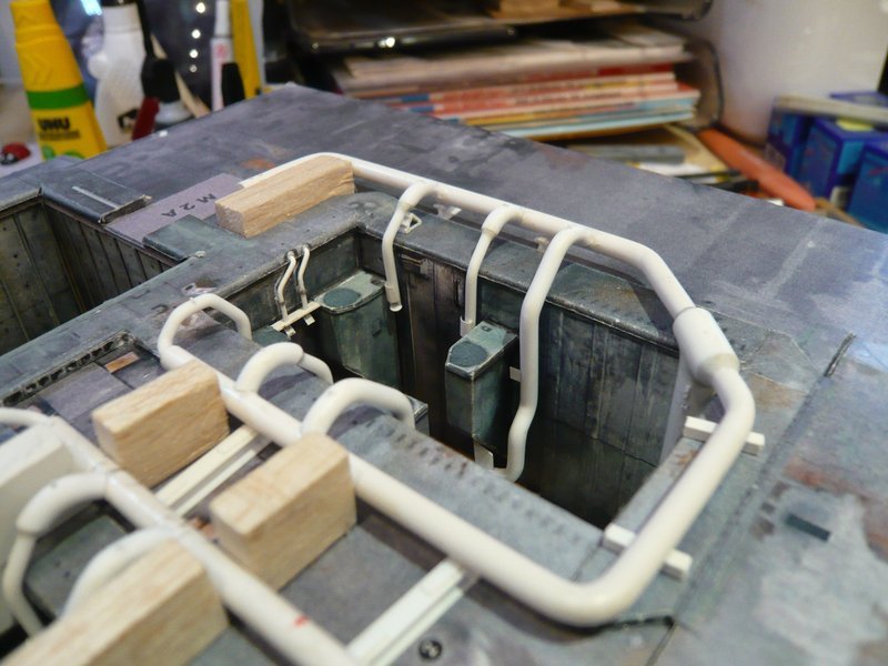
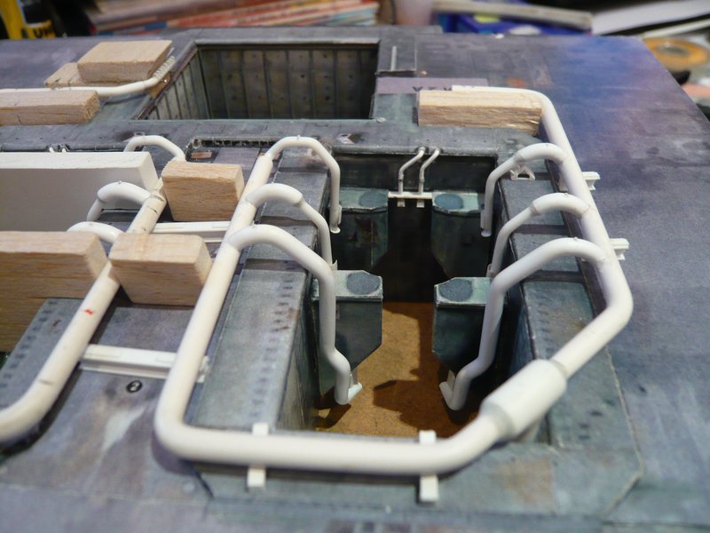
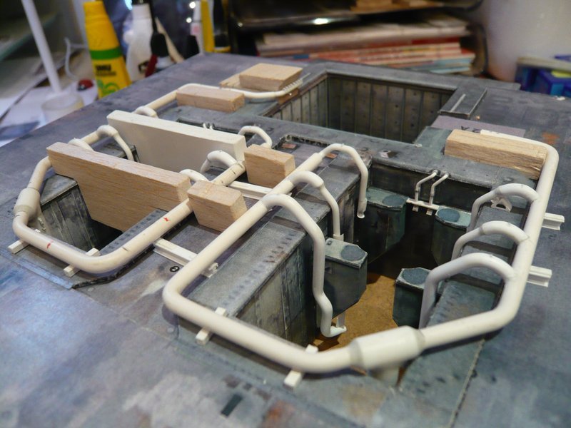
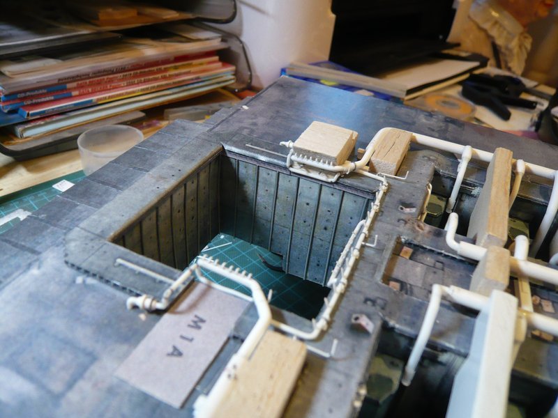
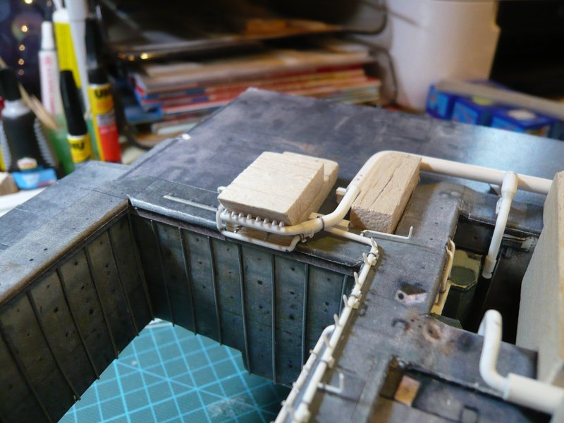
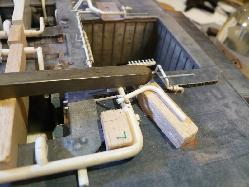
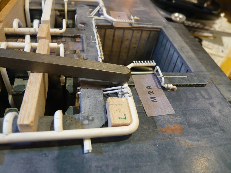
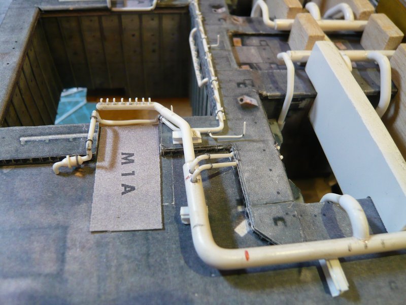
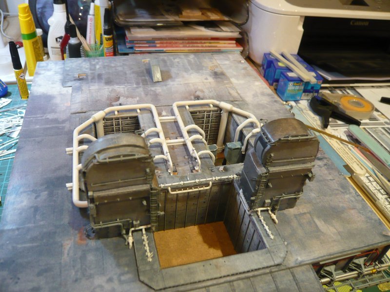
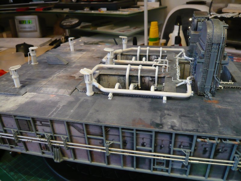
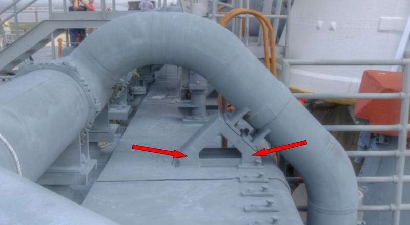
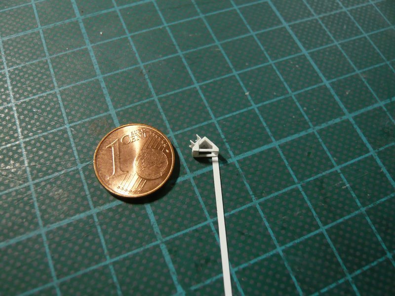
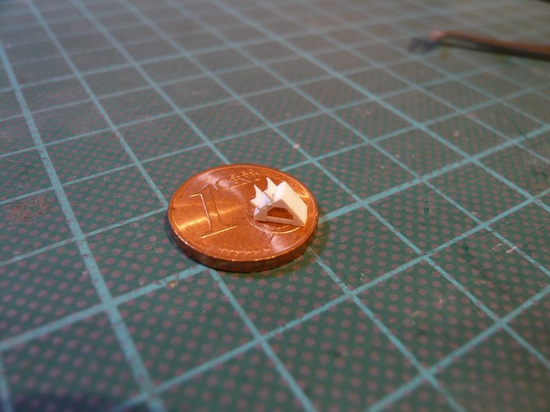
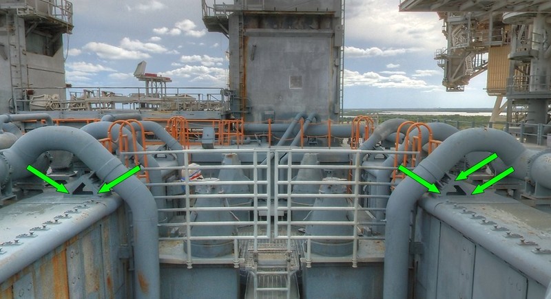
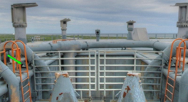
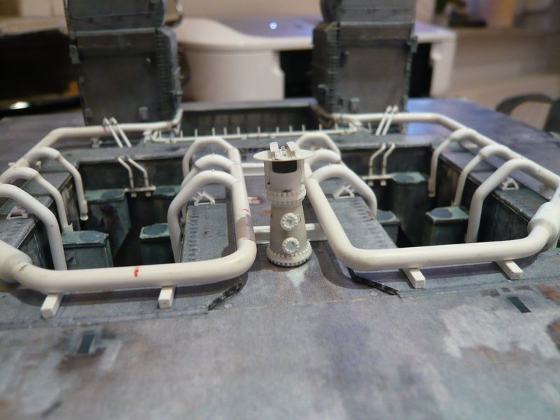
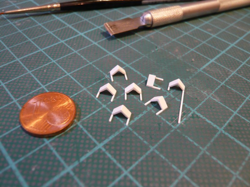
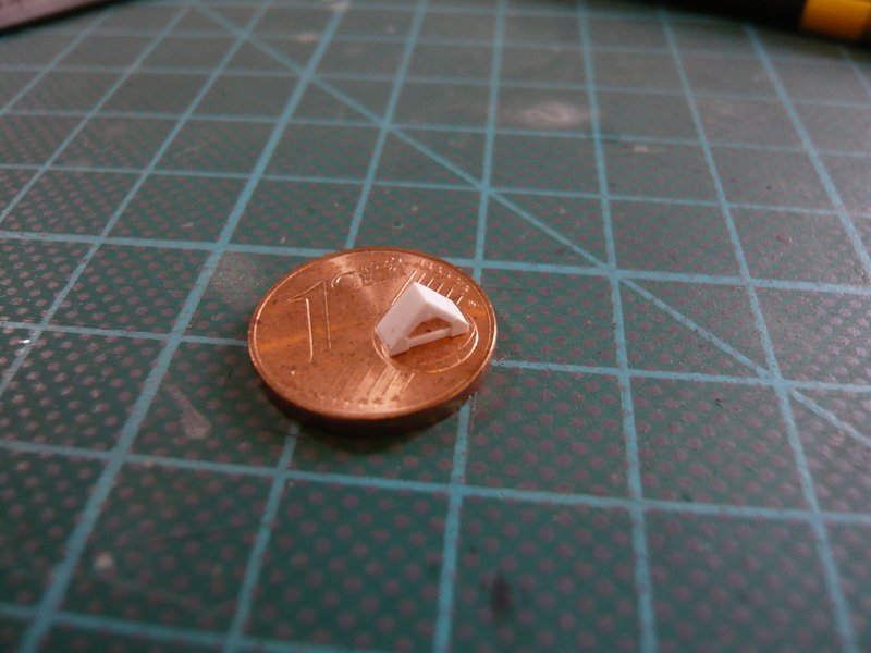
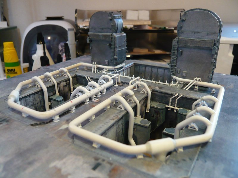
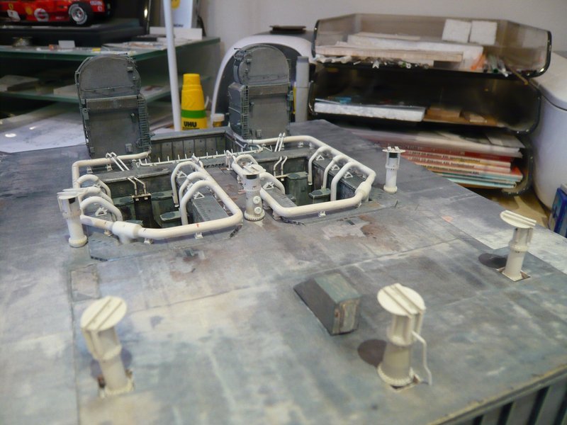
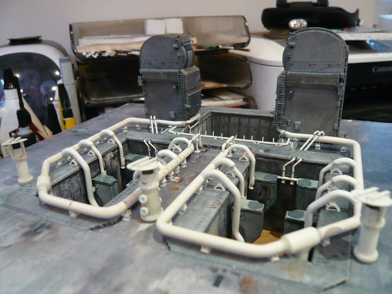
And so it looks then at the supports, wherewith I am for the time being quite satisfied.

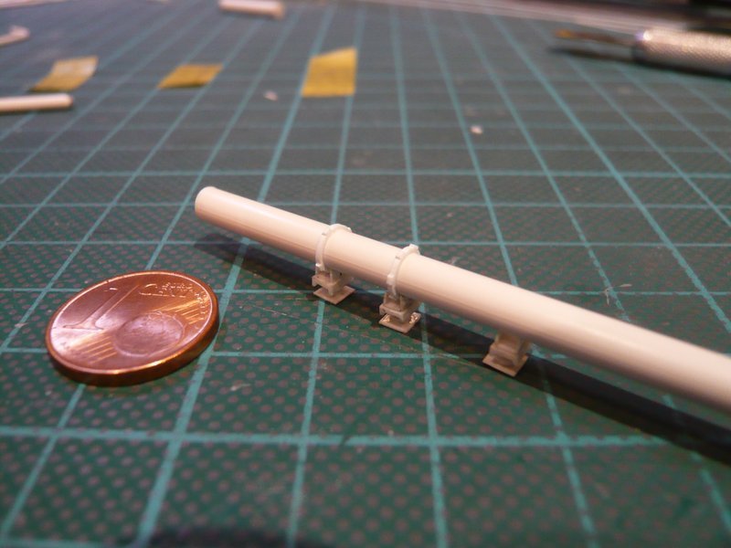
And if one would now round off the edges of the screw connections, it would look even more pleasant from near, which I have tried here at least once on the right clamping ring.

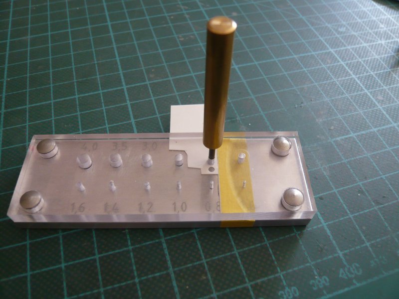
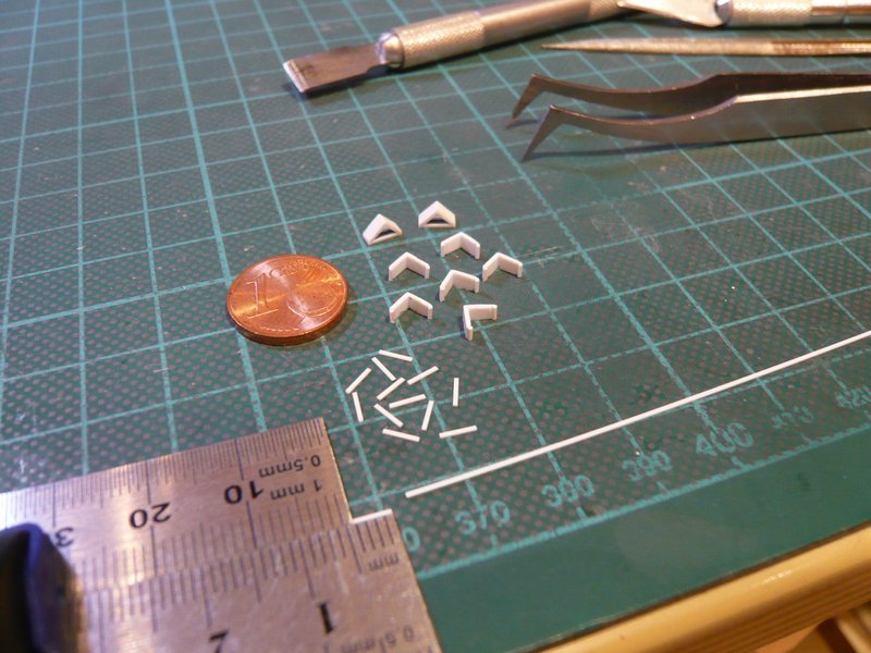
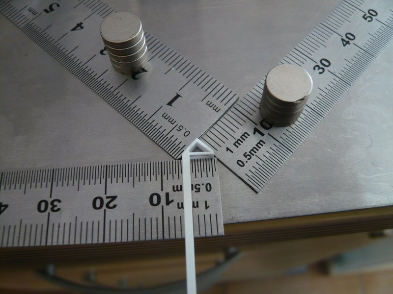
All other clamping rings I now want to scratch however after the Lattice technique, for which I however need appropriate spacers.

For the six-part clamping rings I have already found something suitable with a 1,4 mm x 5 mm rectangular profile, which is a little narrower than the 1,5 mm Evergreen Strips that I measured.

And for the four-part clamping rings, it would have to be about 2.5 mm wide profiles, which I will certainly find out.

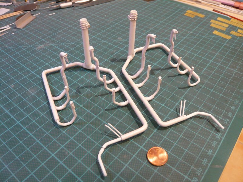
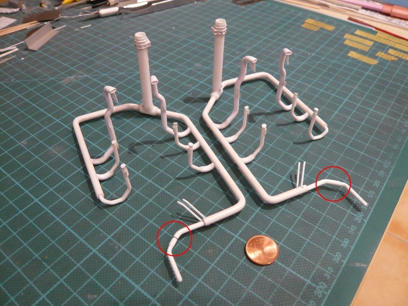
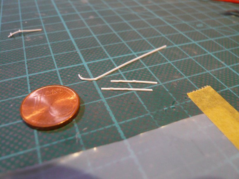
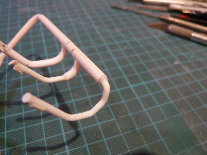
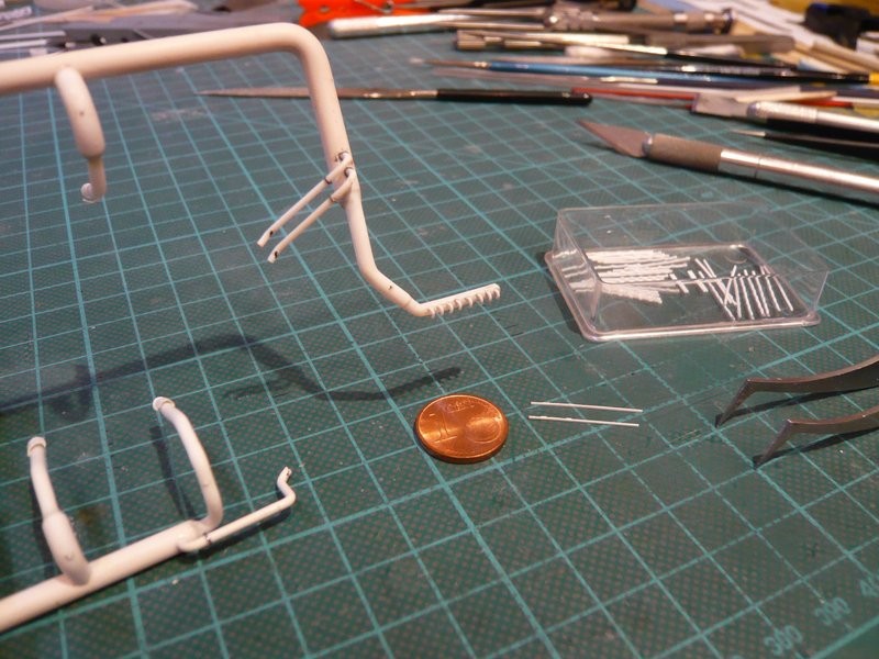
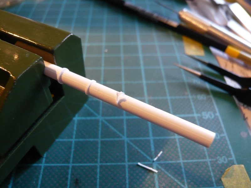
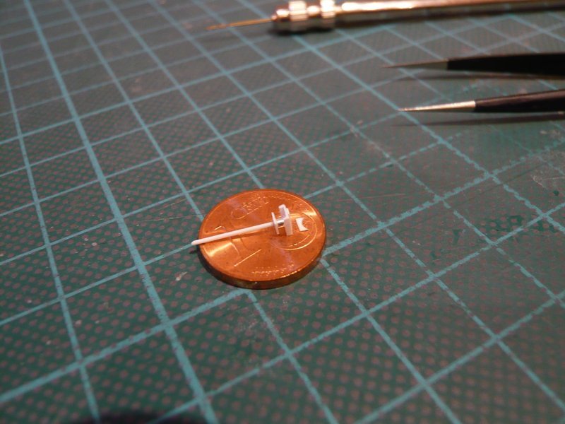
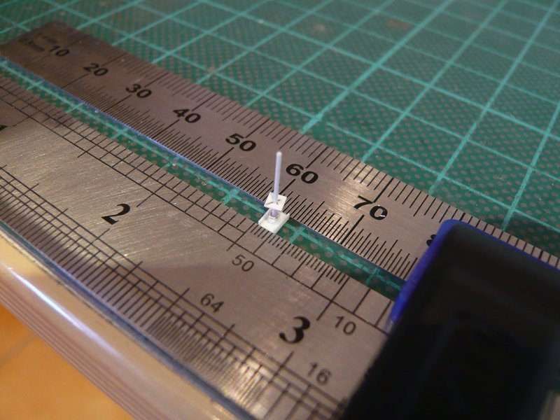
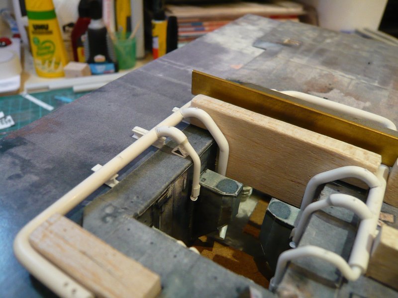
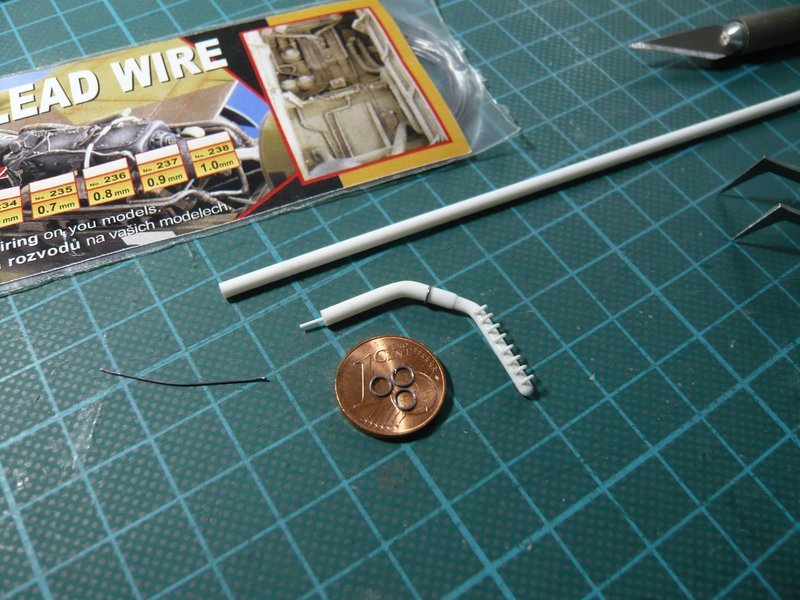
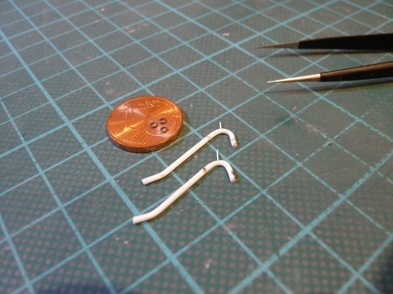
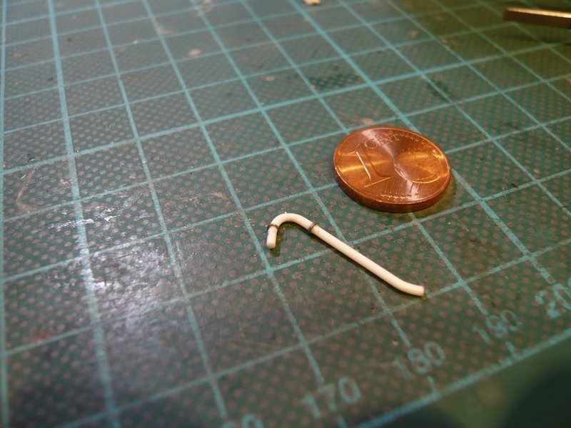
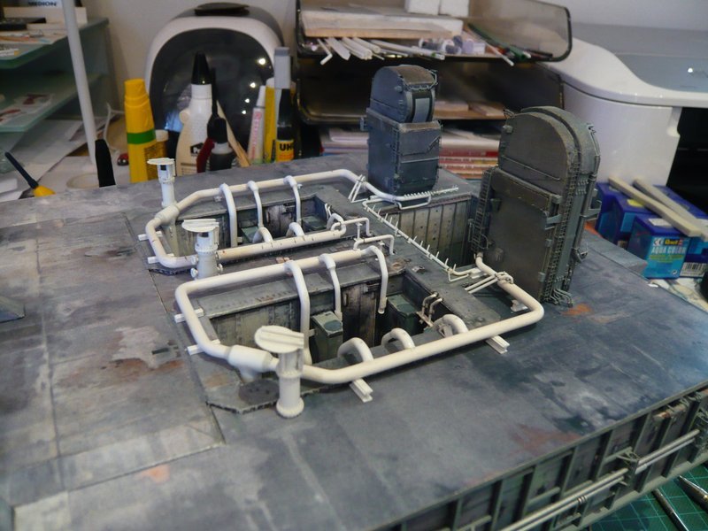
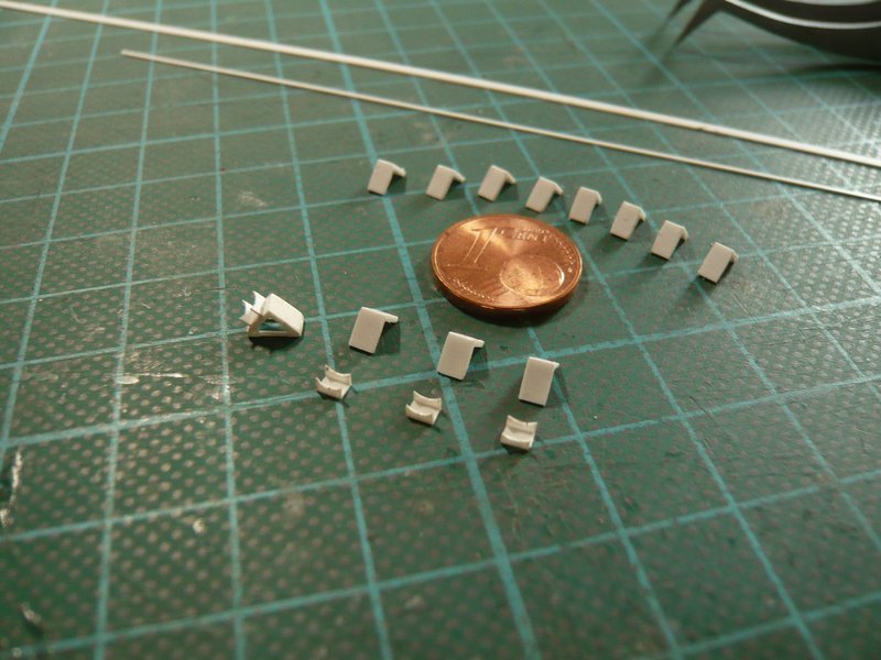
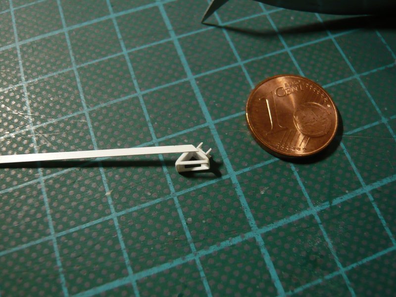
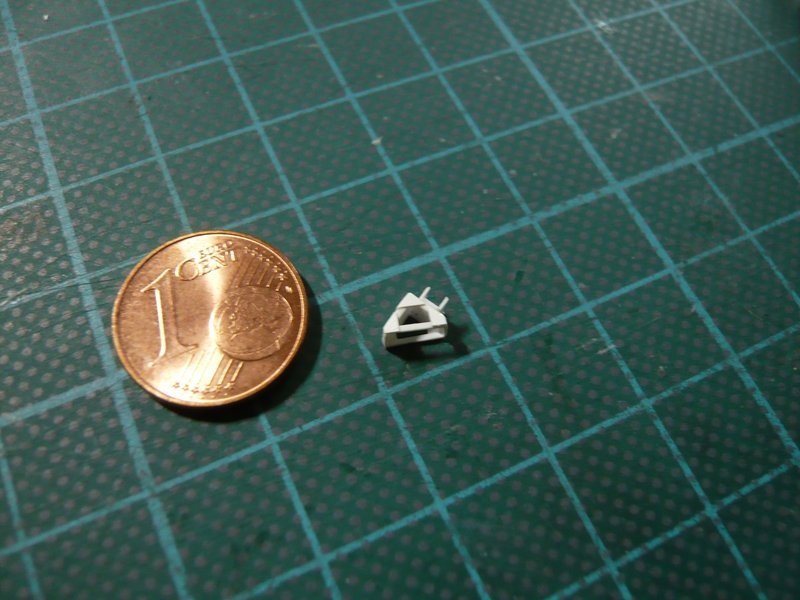
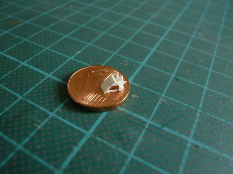
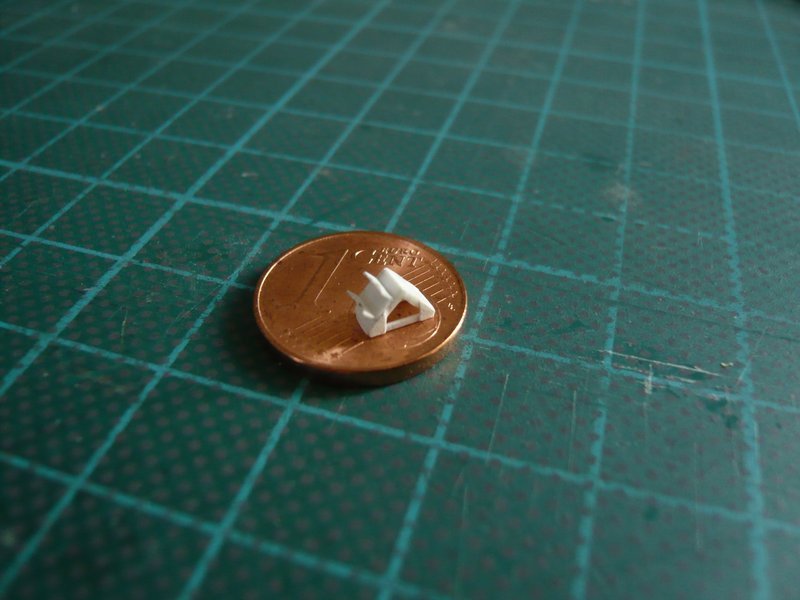
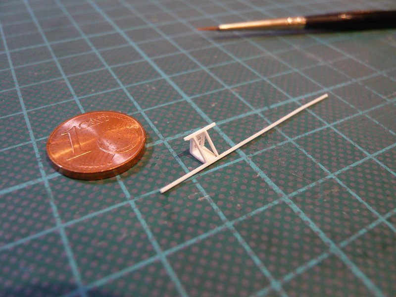
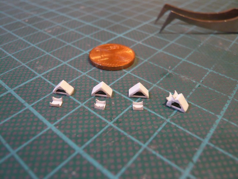
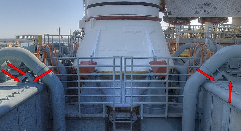
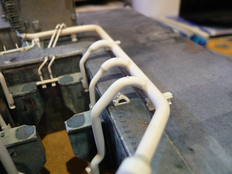
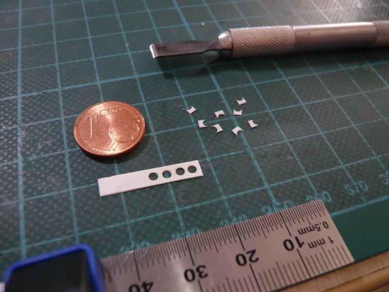
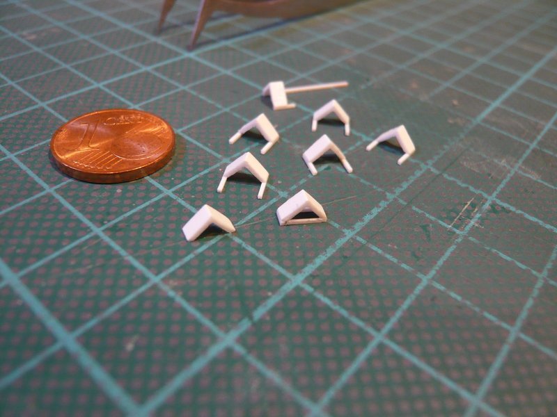
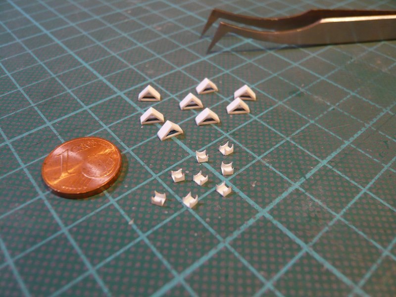
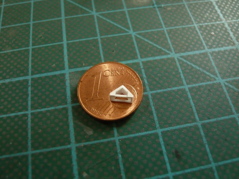
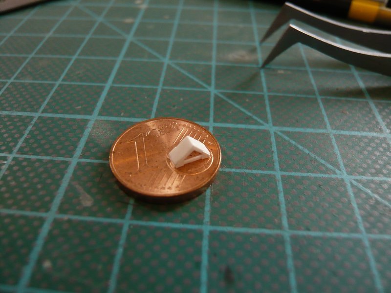
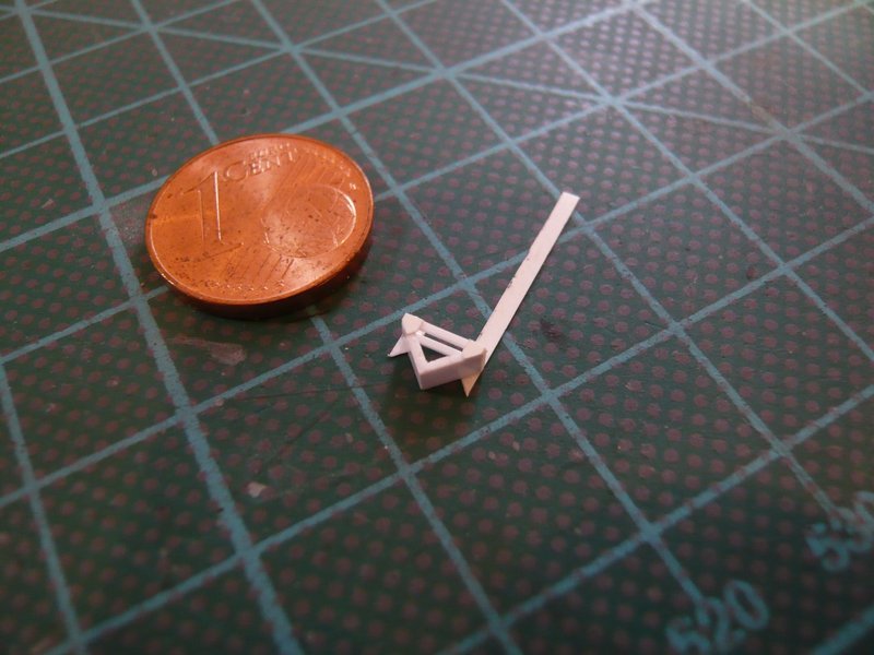
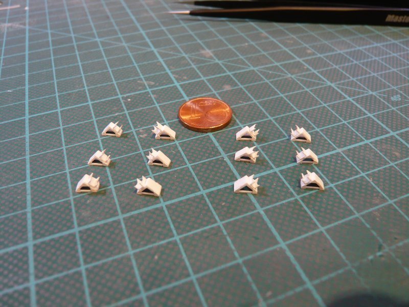
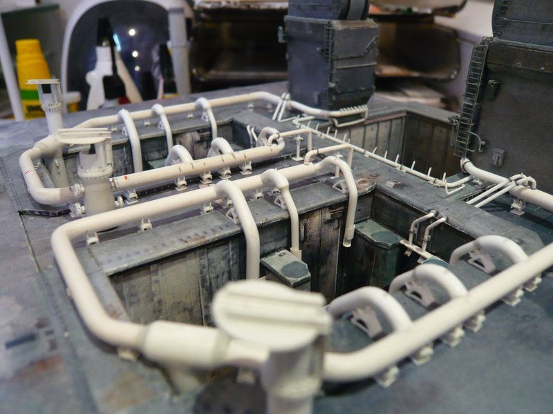
At first I’ve caught up the four-part clamping ring with the longer screw connections (1 mm),

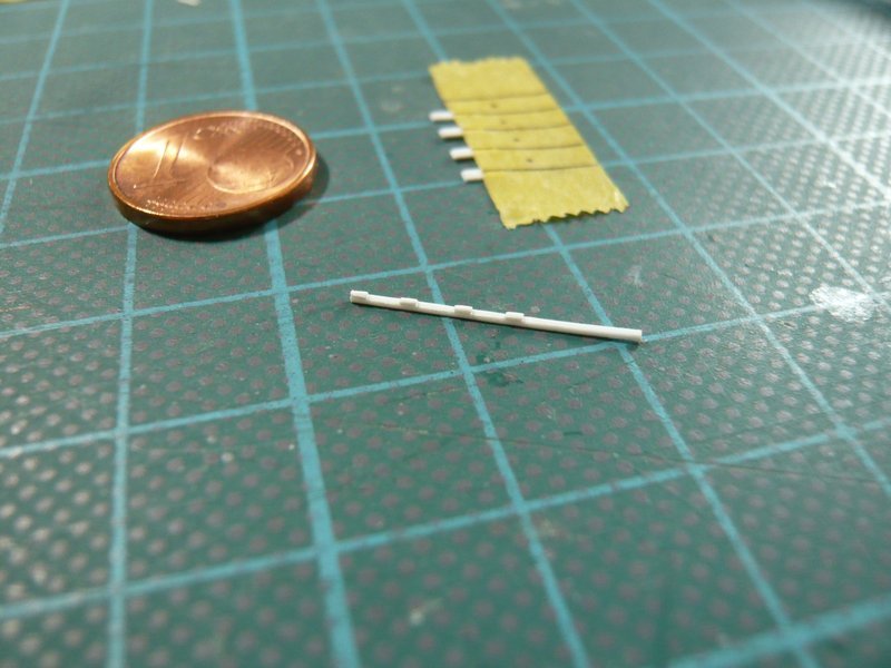
and compared it with the previous one with the too short screw connections (0,75 mm), the edges of which I have also rounded off somewhat.

On this macro image one can still recognize the difference, but from some distance probably already not more.
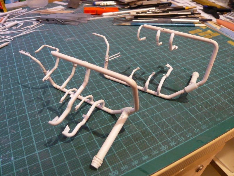
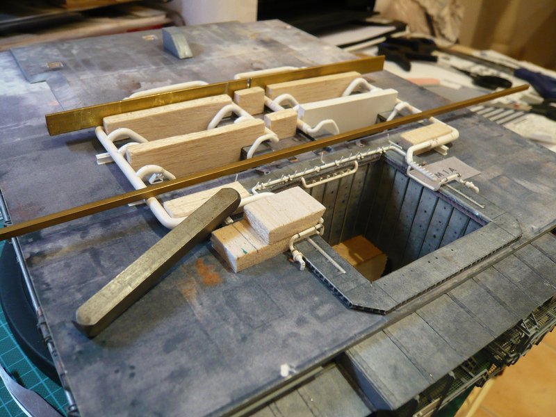
And now to the small series of the nine four-part clamping rings, for which I wanted to apply the Lattice technique.

Originally I had also thought of a similar jig with spacers, as it had worked well for the “cartridge belts” of the Rainbirds. But for these only nine clamping rings then I have renounced on it and have used only tapes.

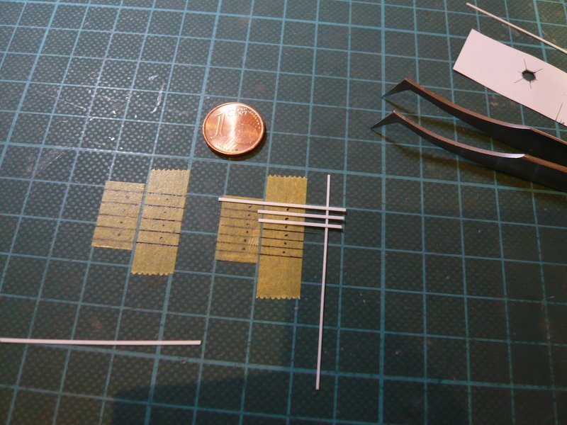
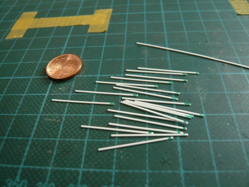
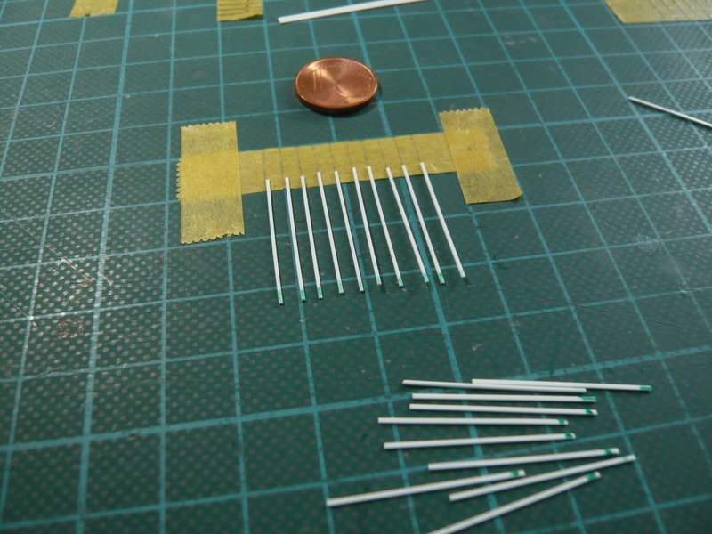
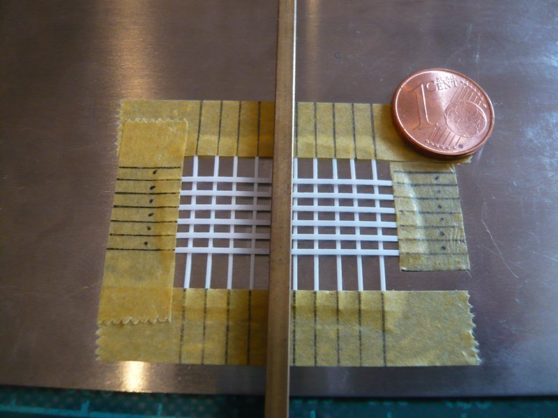
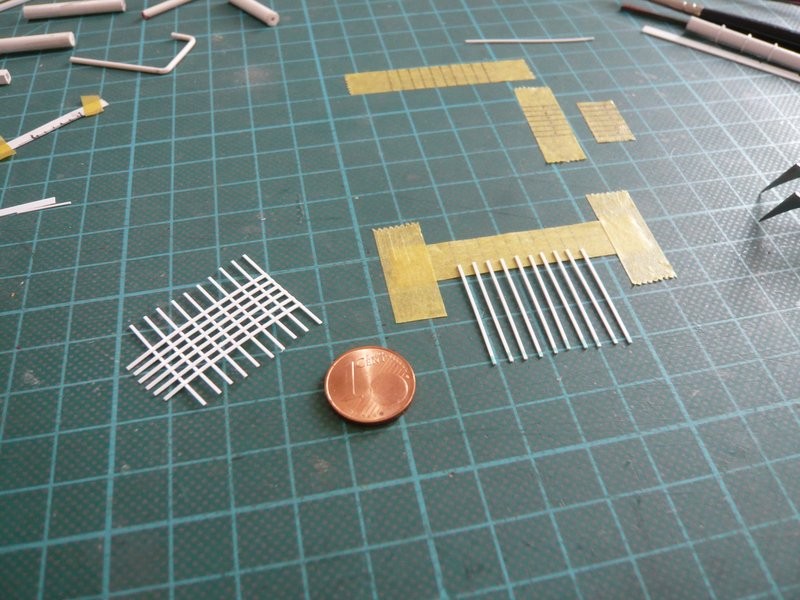
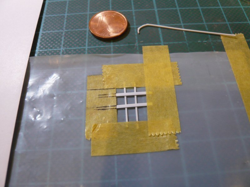
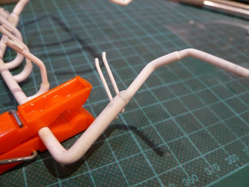
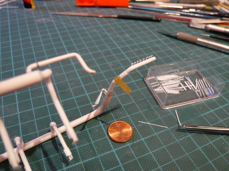
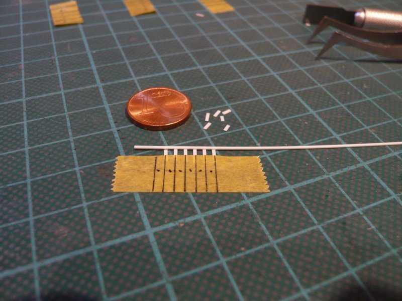
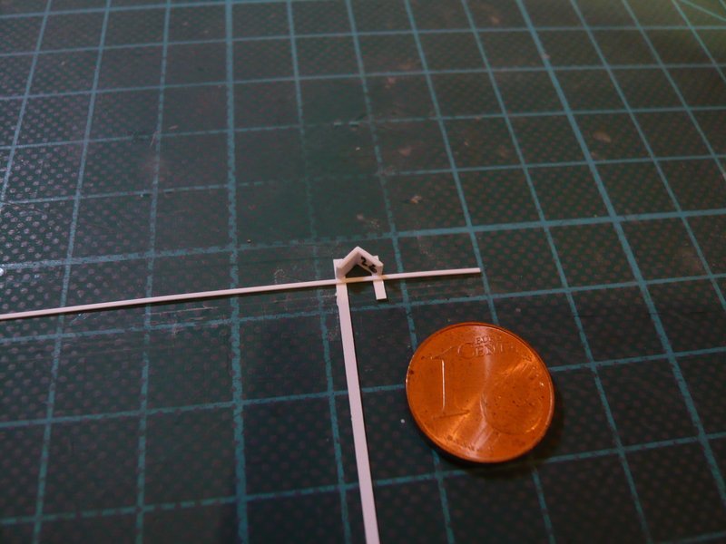
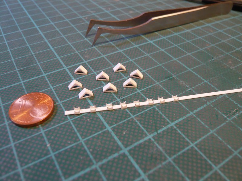
First of all I attached the strips (0,38 mm x 0,5 mm) for the clamping rings with the ends on a tape strip.

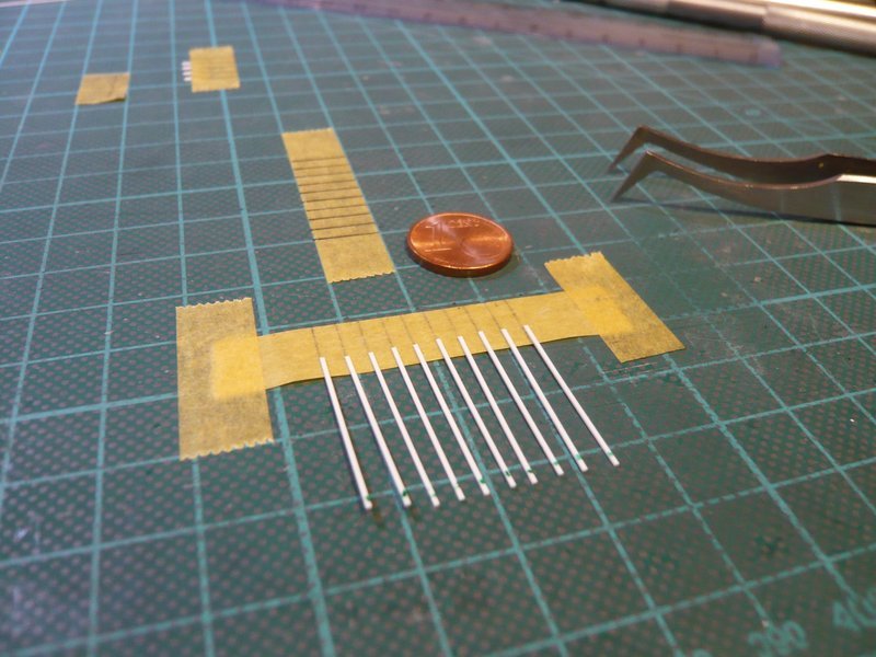
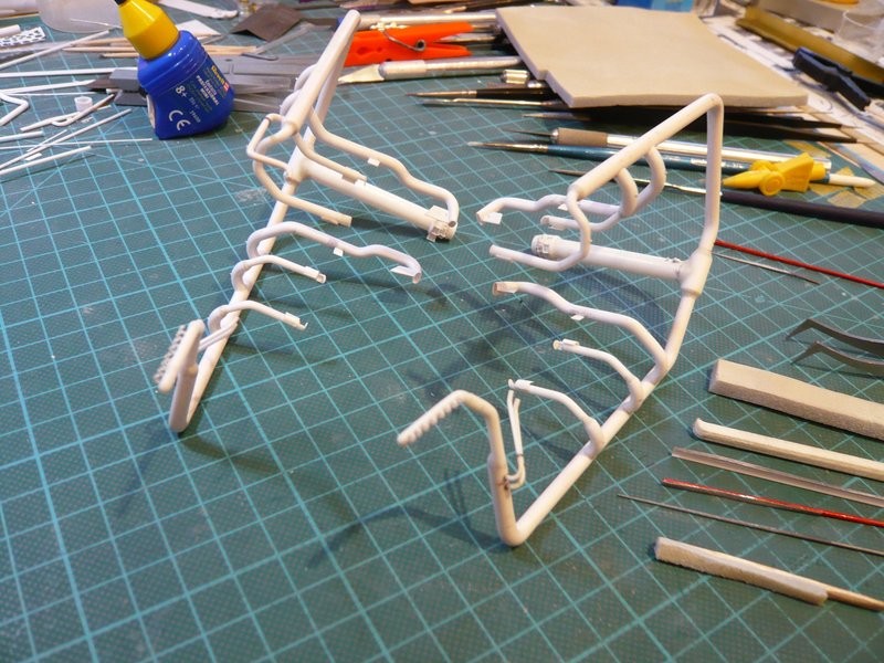
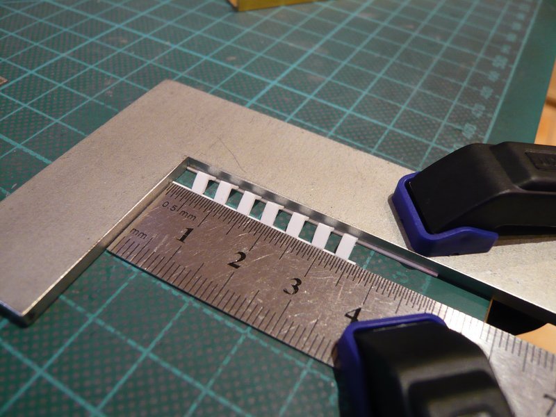
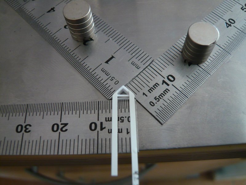
For bonding of the strips (0,25 mm x 1 mm) for the four screw connections per clamping ring with MEK, however, I have precautionally changed over to a metal sheet.

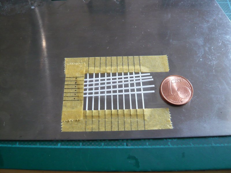
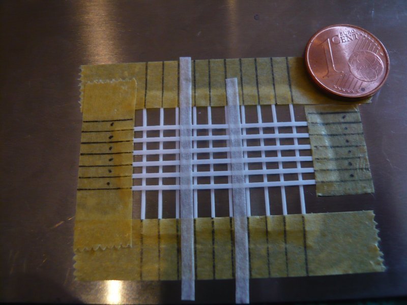
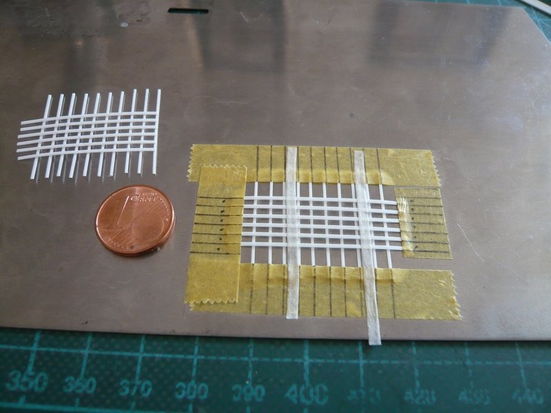
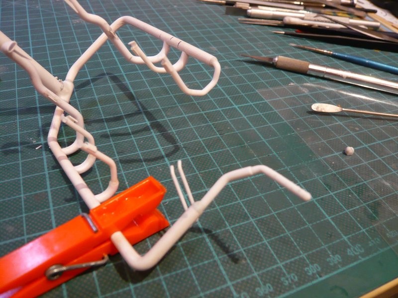
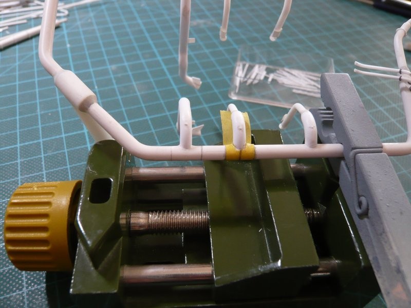
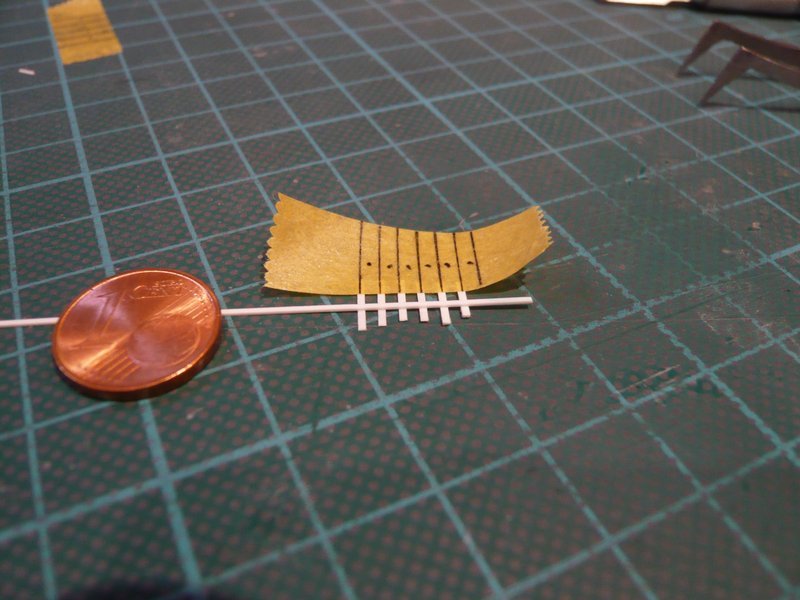
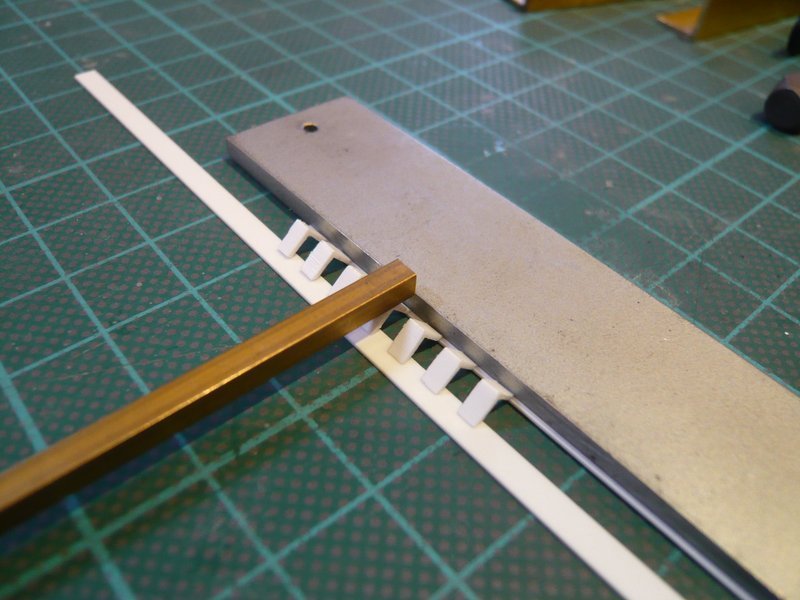
Then I have placed these four strips over the clamping ring strips and laterally fixed with tape.

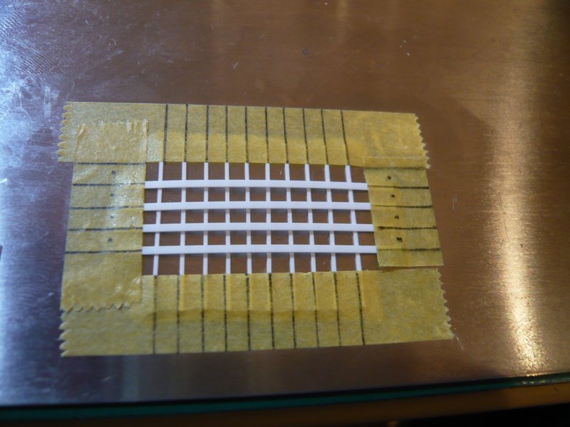
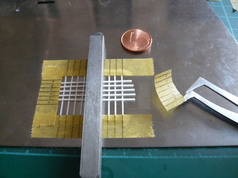
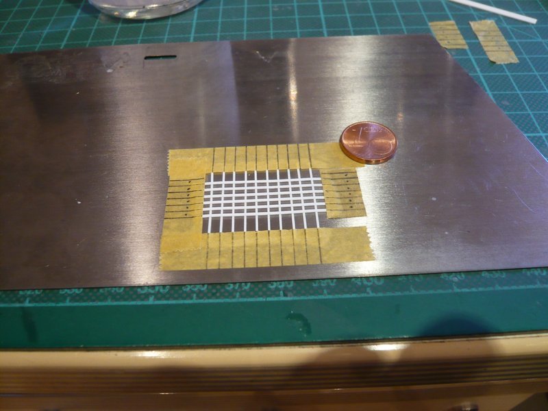
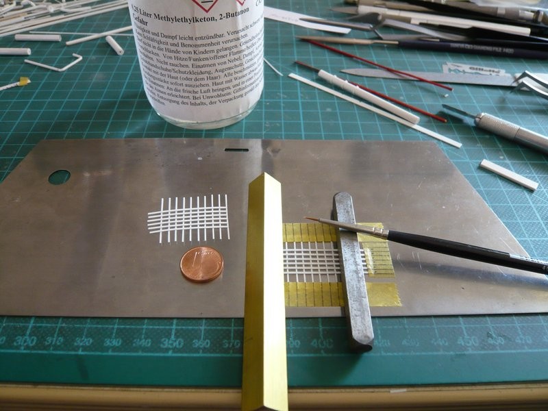
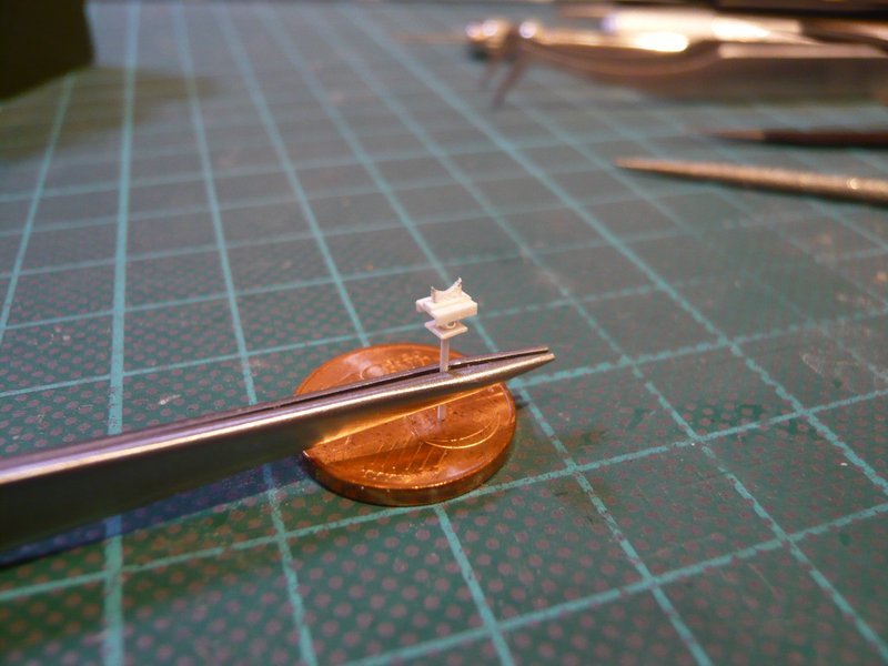
And in order for the screwing strips to lie tightly on top of each other during gluing, the lattice was still loaded by a weight. Afterwards, the superimposed strips on both sides were carefully dabbed with MEK, wherefore a brush tip MEK is really enough.

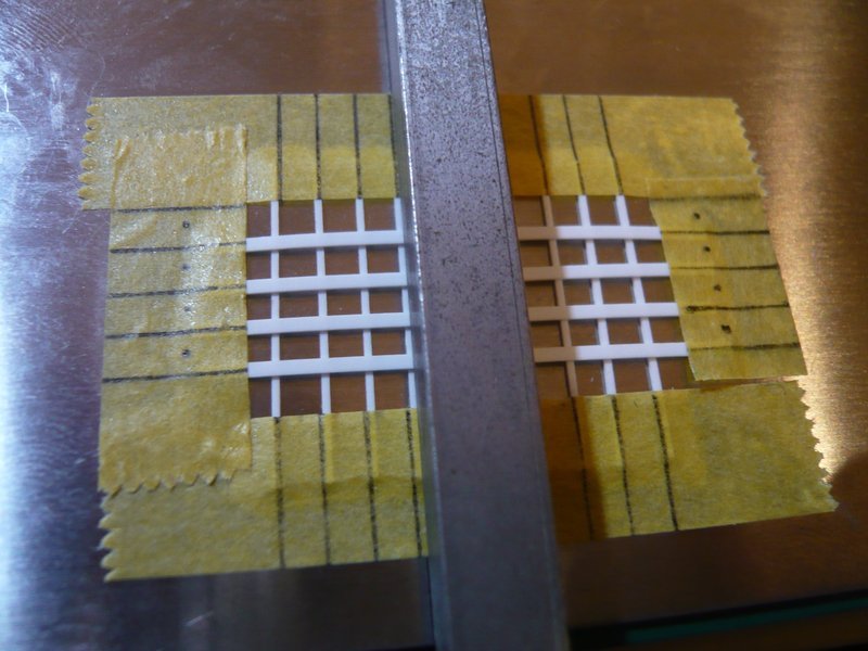
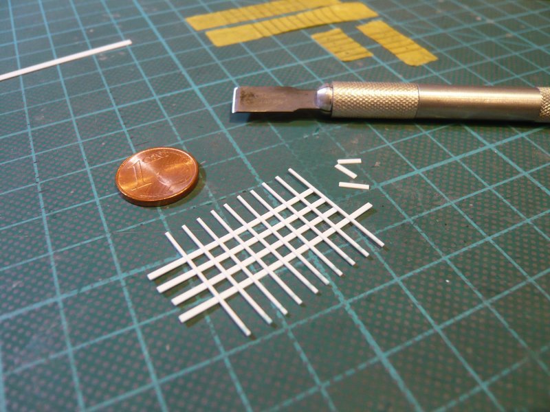
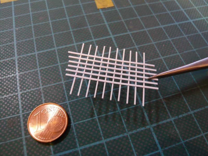
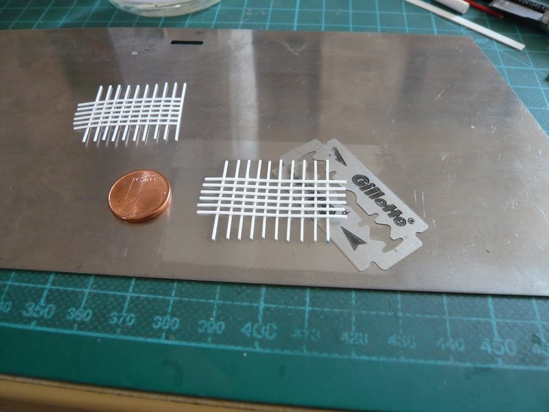
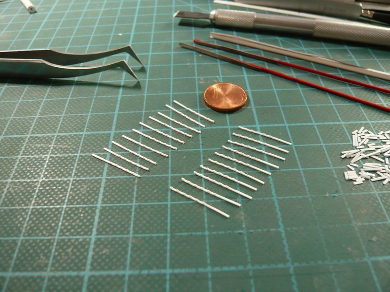
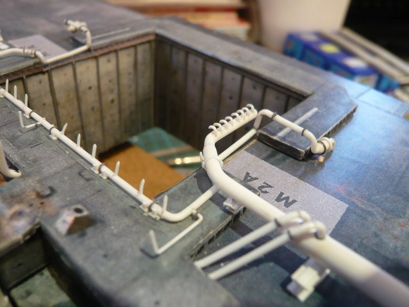
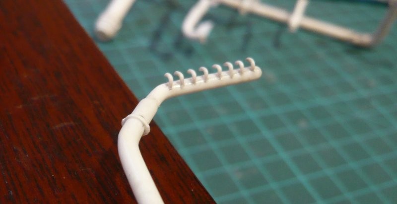
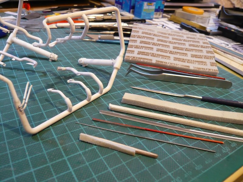
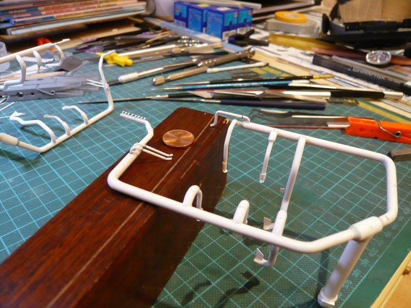
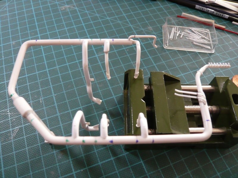
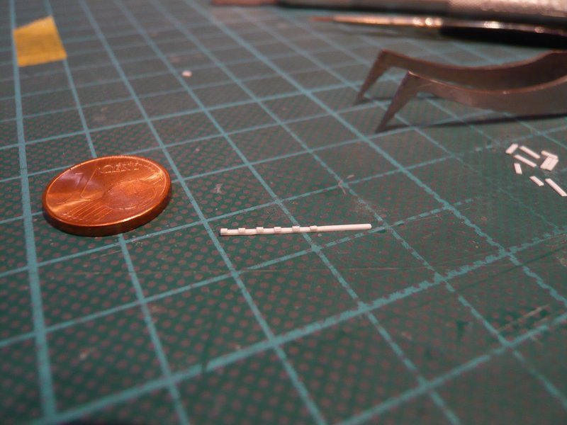
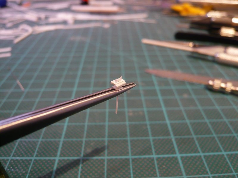
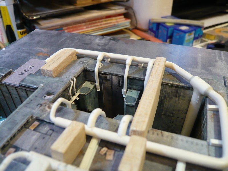
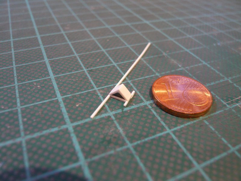
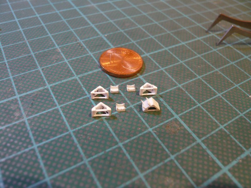
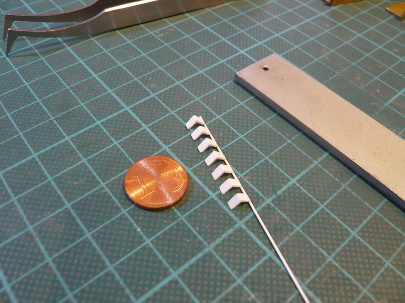
After the same gluing procedure was done on the back, the tape strips could be removed, and the clamping ring lattice was finished.

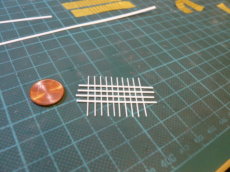
And lo and behold, the lattice is at first sight relatively stable, wherewith my Lattice technique has proved itself.

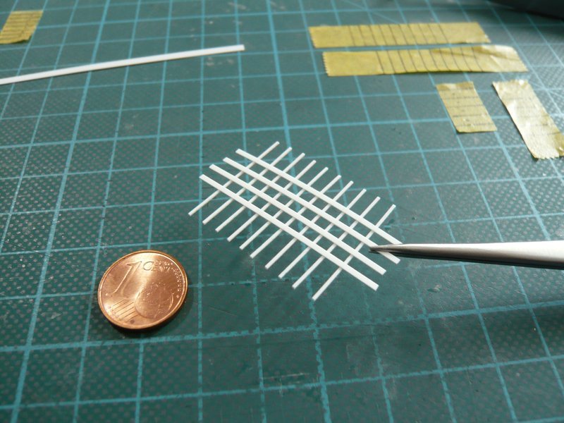
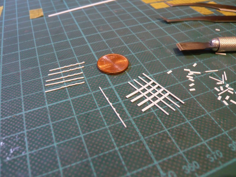
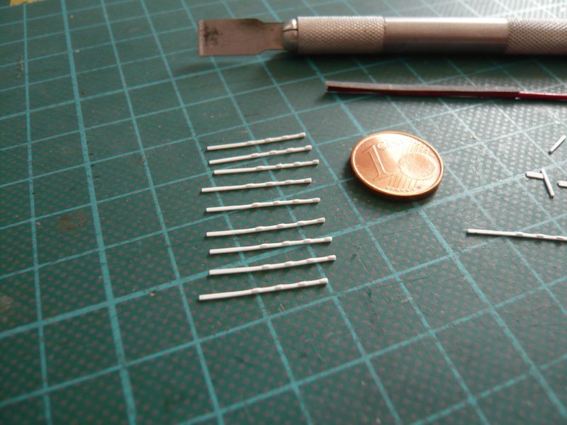
That’s it for now, and next time the clamping rings will be separated.

2 Likes

Hi everybody,

even if it is currently something tiring, here it goes on with the clamping rings, it is no good …

Since the rounding of the edges on a single strip is quite difficult and stressful, I have not completely separated the lattice, but only the outer overhangs are cut off. As a result, the outer side of the clamping ring, including the screw connections, can be rounded off relatively comfortably over the entire length since the lattice itself is surprisingly stable and flexible.

On the other side of the strip, one has to work carefully, particularly when rounding off the interstices, for which I have made myself a 1,5 mm narrow grinding stick.

This business was very time-consuming, but then the nine clamping rings were finally (like myself) done.

How good that I had planned a spare strip, because at one strip, during rounding off actually one screw connection was canceled.

After the four-part clamping rings were securely stowed in a small box, I kept doing with the six-part rings, however 19 of them are needed.

For the clamping rings 0,38 mm x 0,5 mm strips were again used, and 0,25 mm x 0,75 mm strips for the shorter screw connections.

I will use the same method again to prepare two lattices each with 10 clamping rings, because the size had been okay.

In order to hold down the screw connection strips, they had to weight again,

whereby I almost had forgotten one strip.

After the transverse strips were aligned once more, in order to have approximately equal distances, I have additionally glued two narrow masking strips, so that the lattice can not slip during MEK gluing.

Then all the lattice junctions were glued together on the top side,

and then on the bottom.

And with the first lattice again a small step was done, the next will follow soon.

4 Likes

Hi all together,

and thus in the fast passage to the second clamping ring lattice with the known procedures:

Fixing the longitudinal and transverse strips,

as well as gluing the cross points with MEK.

The lattice, which has been smoothly adhering to the sheet metal, can easily be detached with a razor blade.

After that the stressful rounding off of the filigree edges had to be done again, which this time because of the closer distances of the screwing strips was somewhat more difficult.

That’s why I’ve come up with a narrow mini-file for the narrow spaces, for which I have glued a 1 mm wide strip of fine sandpaper (500) to a 2.5 mm Evergreen channel.

And these first ten of the required 19 six-part clamping rings are the result of this laborious fiddling.

Now I have also disassembled the 2nd grid and rounded the edges on the remaining 10 clamping rings and their screw connections on all sides.

And I can tell you, with the last stripes my eyes began to tear more and more, because in the long run this is too strenuous, because the edges are so tiny.

That’s why I’ve counted once for fun the edges, which I have rounded off with my mini-files at the total of 28 clamping rings.
And what would you estimate if I would ask you?

Well, since I myself was surprised, I’m going to say it immediately: believe it or not, a total of 900, hardly to believe but true !!!
And now it’s time to get the SSWS skeletons out of the SRB Holes in order to glue all the clamping rings.

But first I have to deal with the transitions at the outlets and to model them with Apoxie Sculpt.

4 Likes

Hello together,

but before I start with the Apoxie Sculpt modeling, there’s still something else to do.

After removal the ring lines, I have noticed that in front of the 16’‘/12’’ transition behind the LOX-TSM the clamping ring still lacked, as one can see in the right circle.

The rings for this I had (only) bent from lead wire (Ø 0,4 mm) at that time.

But in reality, these are two-part clamping rings with laterally fitting screw connections,


Source: nasatech.net


Source: nasatech.net

which could also be made by the successful lattice technique.

And just during this consideration, a friend from the Raumcon Forum has sent me a piece of Teflon foil (PTFE, 0,05 mm), which I should try as underlay during the MEK gluing.

Onto this idea one must only come up, especially since PTFE is known for its excellent anti-stick properties.

For as you may remember perhaps, the strips lattice glued with MEK adhered on the metal sheet, which surprised me.

And I have now tried the same with the both two-part clamping rings, meaning no metal sheet than underlay, but only the Teflon foil on the cutting mat on which the clamping ring strips were fixed.

Subsequently, the crossings were dabbed with MEK as before and so glued.

And lo and behold, nothing remains adhered, and the bondings can be removed from the foil easily and without any problem.

And these are the two clamping ring strips with the two screw connections.

As far as for today.

1 Like

Hello everybody,

unfortunately I’ve got a lumbago, what is not so funny, but when sitting comfortably, it is still tolerable, so I once tried one of these both two-part clamping rings. Because of the smaller pipe diameter (2,5 mm) this time I used an Evergreen strip 0,25 mm x 0,5 mm for the ring, and for the screw connections 0,25 mm x 1 mm.

I hope one can still recognize the clamping ring behind the bow,

this one here is it,


Source: nasatech.net

and therefore here once somewhat larger.

Subsequently, I have started modeling the transitions at the rejuvenations of the ring lines and first rolled [color=blue]Apoxie Sculpt[/color] balls and then mixed them.

Here is the preliminary result, first at the 24’‘/12’’ transition, which is still accessible relatively easy,

and then here at the 24’‘/16’’ transition, which was somewhat trickier because the two 6’’ outlets are unfortunately in the way.

On the occasion I have also installed one of the two 9’’ transitions, for what I had to insert the ring line again into the shaft, which however against expectation has worked, also without removing the SRB Supports.

Now everything has only to dry, then the transitions still can be reworked somewhat.

That’s it for today.

1 Like

Hello everybody,

in the meantime, the modeled transitions have been carefully plastered on both pipe frames, using different tools for grinding to reach to the respective points.

These were for the bigger roundings beside normal grinding sticks also again my handmade small sticks as well as fine files and especially Grinding sponge (Tamiya-2000). Since the grinding sponge adapts particularly well to the contours, I have glued a small sponge stick from a narrow strip and a balsa stick, with which one can carefully grind around the transition without producing unsightly nicks.

Since hardly any rework was required on the 18’’ outlets, existing unevenness were eliminated with a thin needle file (Ø 1,0 - 0,5 mm).

Now also the other 9’’ transition on the ring line behind the LOX-TSM could be glued, whom I had to give especially care while further handling, since the glue point with Ø 1,5 mm is highly sensitive and extremely fragile.

The thin support rods under these transitions can only be glued at the very end, because their support webs are simply too narrow and would hardly provide support.

Then the other two-part clamping ring came next into line.

After I had marked the position of the screw connections with a tape strip,

the clamping ring was glued step by step.

Thereby the two ring lines are now finished, so that now the 28 clamping rings can be glued, which certainly will become a stressful affair.

At first, however, the positions had to be marked, for which I have used a small tape template, which was very helpful.

And now my drawing of the ring line behind the LH2-TSM came again into the game,

by means of which I marked the position of the six-part (green) and four-part clamping rings (blue) on the ring line, therewith nothing can get jumbled, because the arrangement of the clamping rings on the ring line behind the LOX-TSM looks a little different.

So it can now finally get started with the clamping ring orgy, of which I already a bit dread. Because this time I have to go back again to the CA, because with MEK the disaster would be preprogrammed, if you can remember, long, long time ago …

The important thing is a secure holding of the ring line, in order to be able to position the clamping rings correctly, because the first contact has to be fixed straight away, especially since correction is extremely difficult. Because if the starting point does not glue, one has to clean the glue point again, because on the old CA strangely enough no new CA glues.

Bye for now.

4 Likes