Space Shuttle Launch Complex 39A with Challenger STS-6 (1:144)

Hello everybody,

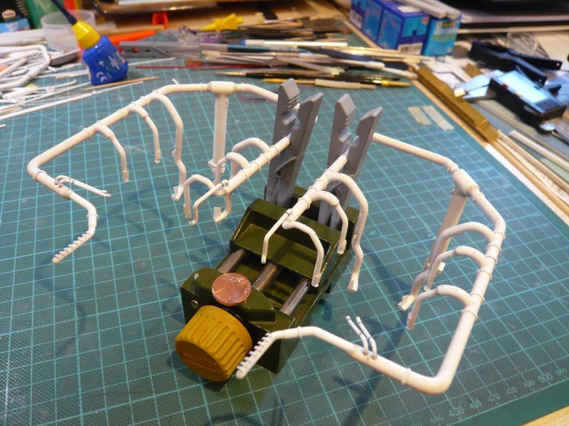
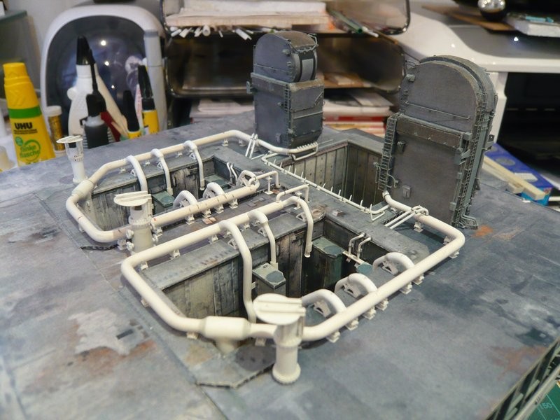
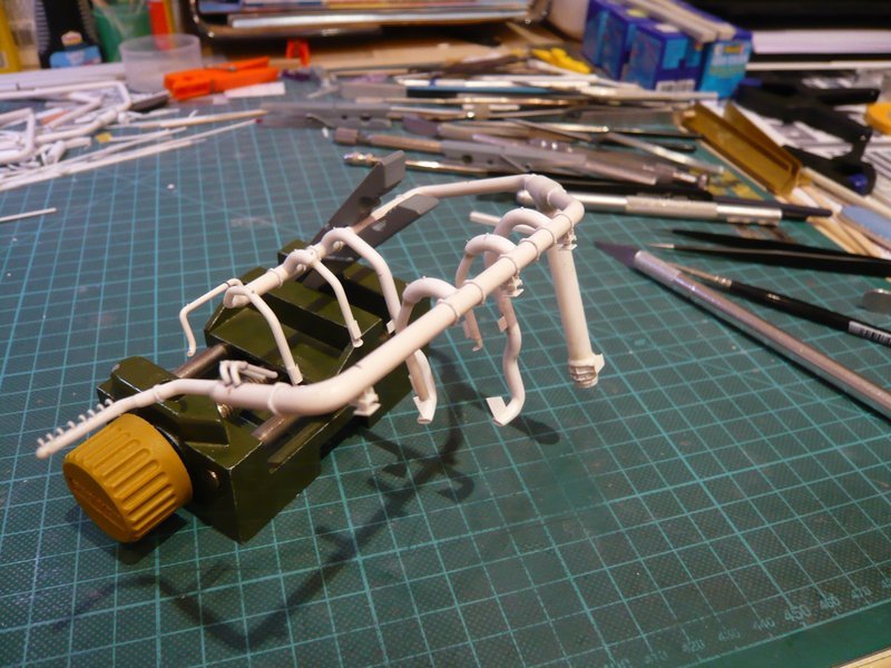
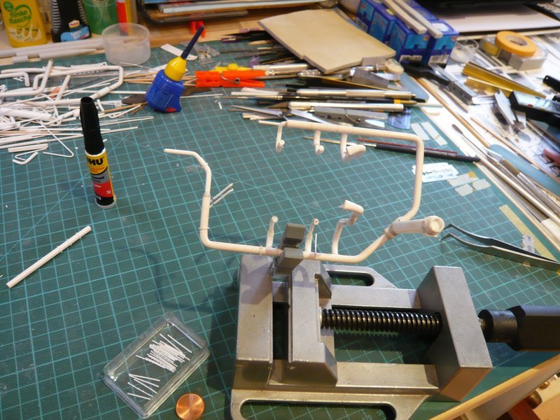
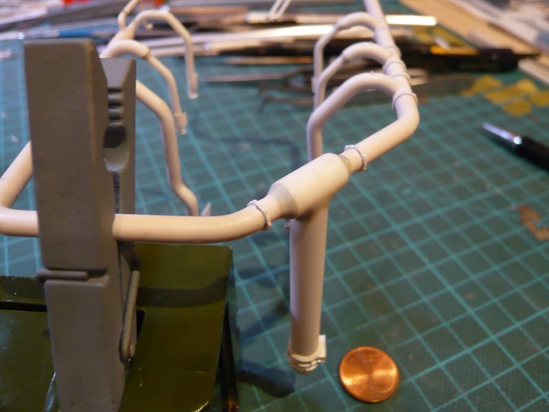
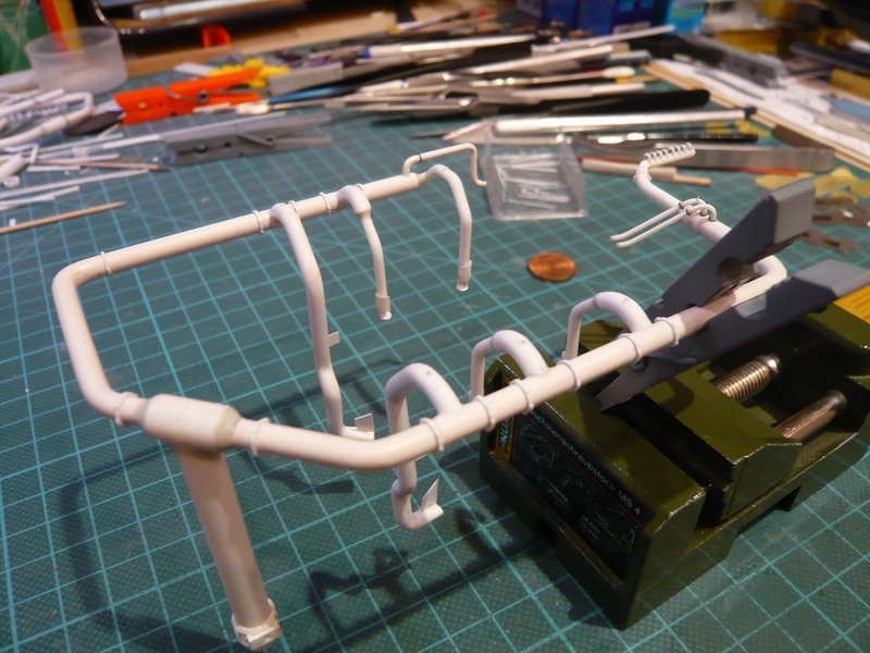
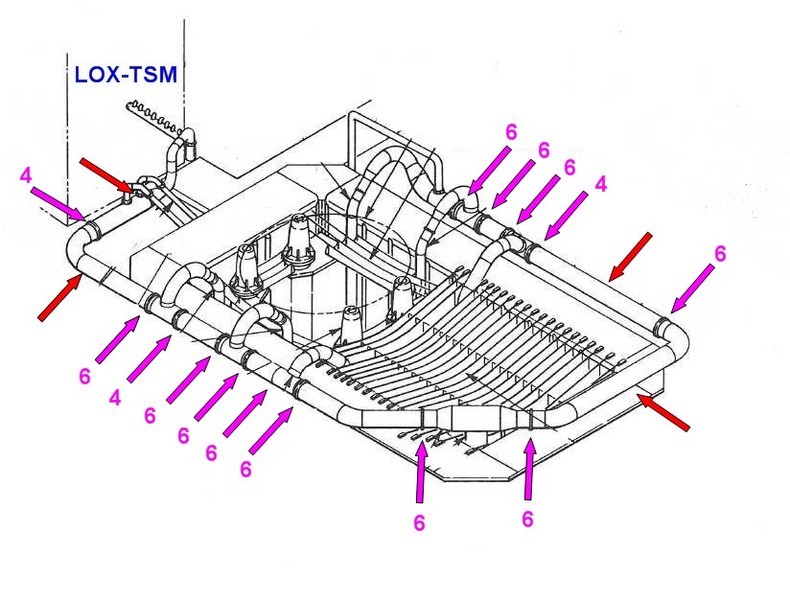
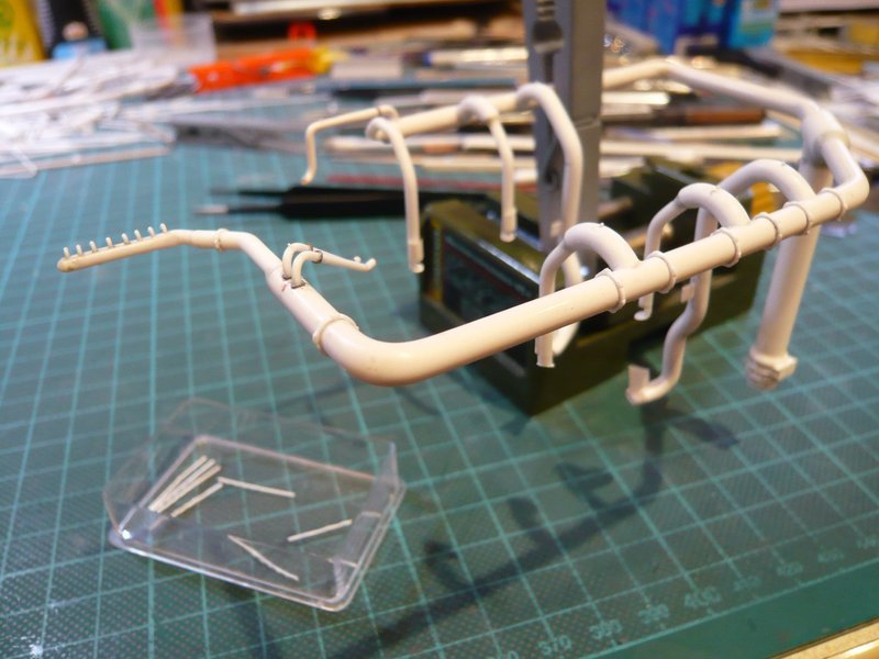
now for the gluing of the first clamping rings on the ring line behind the LH2-TSM, which has proved to be the expected tricky affair to do.

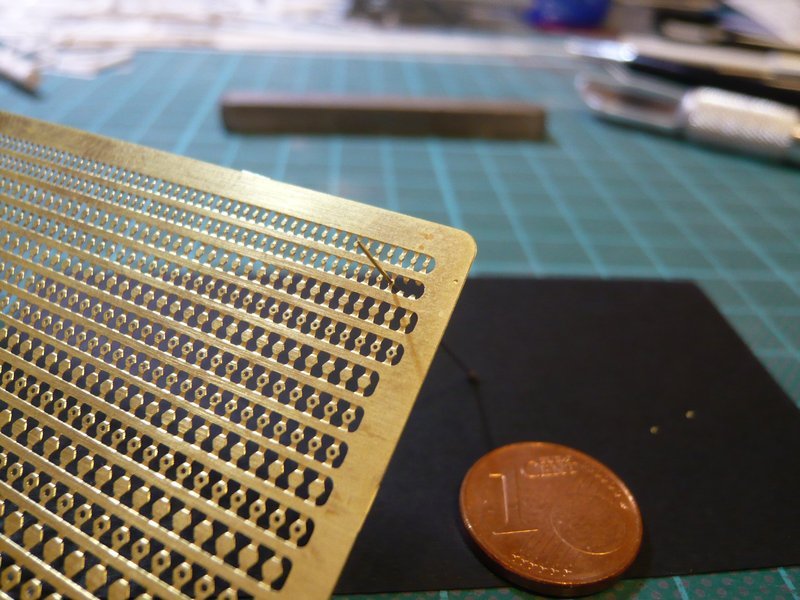
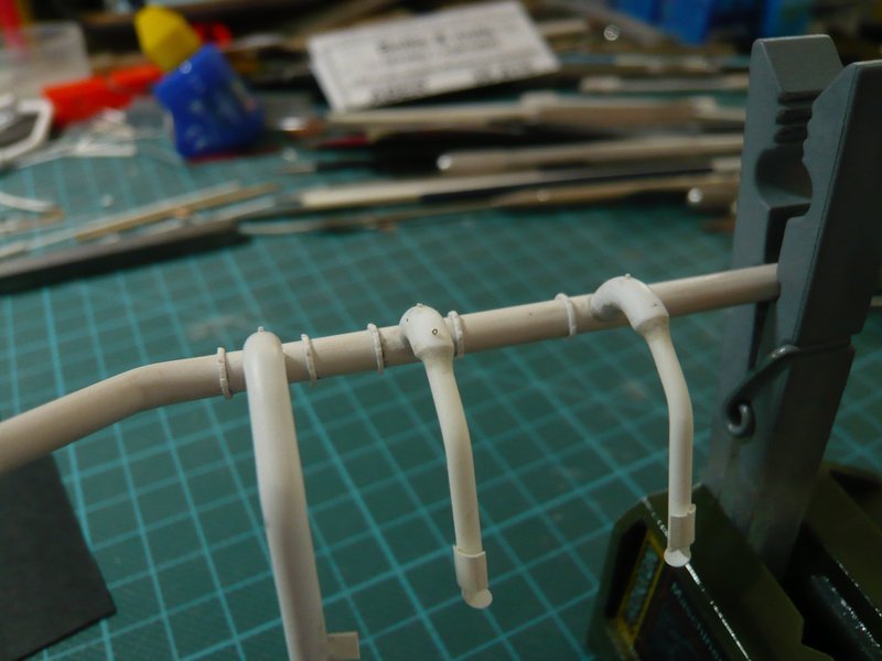
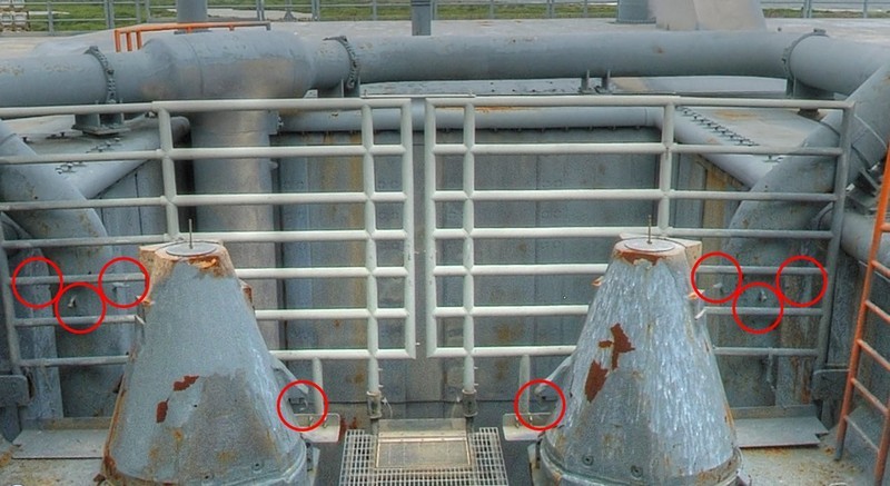
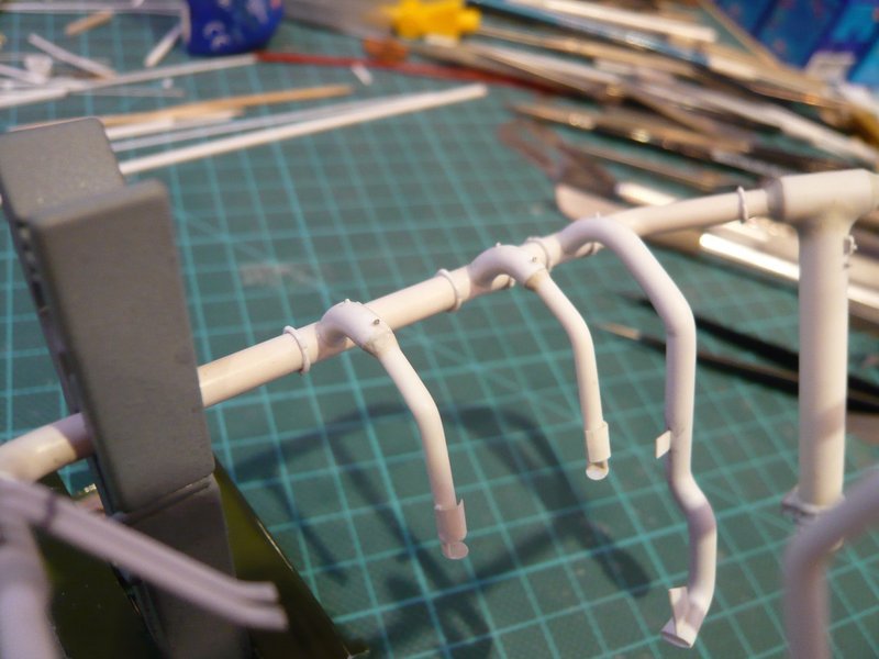
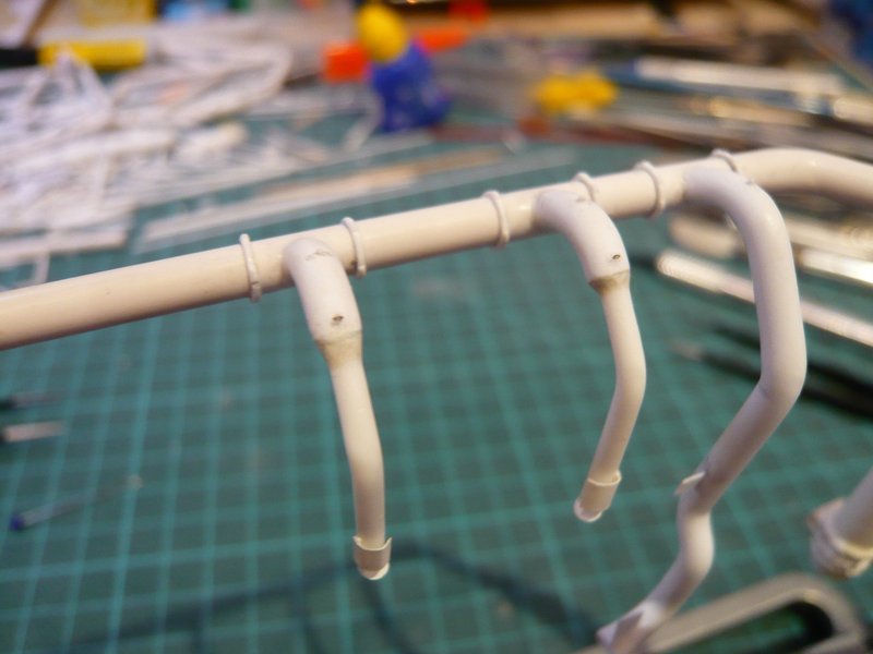
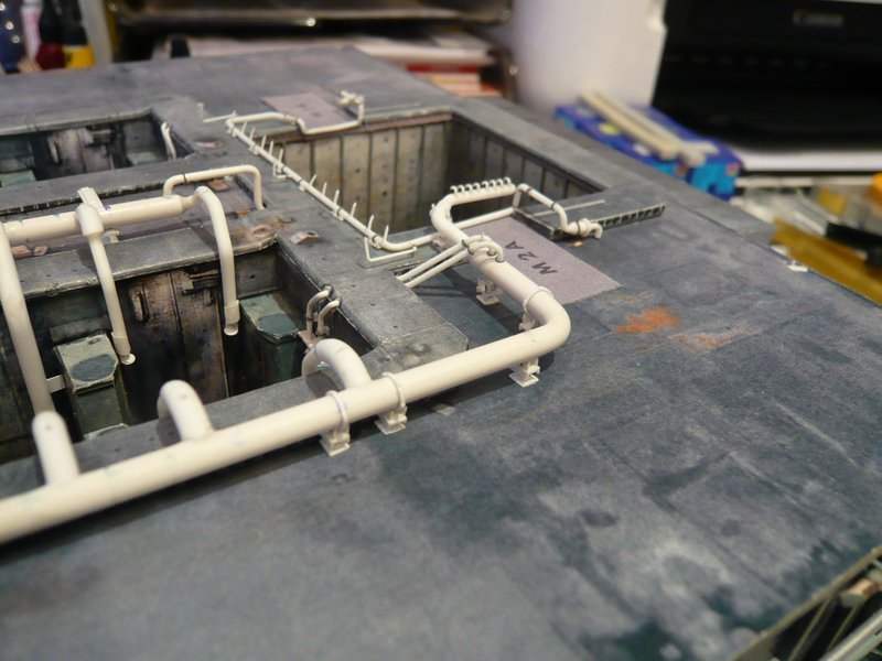
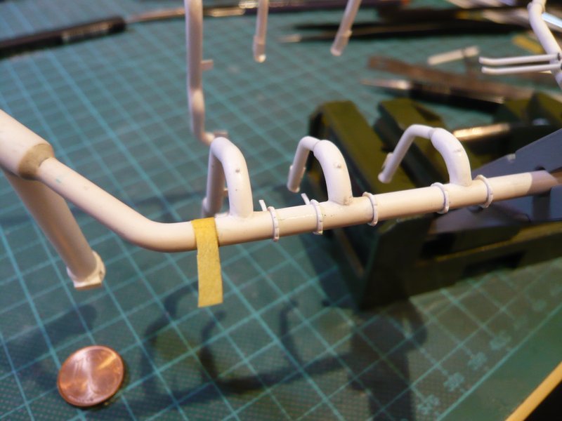
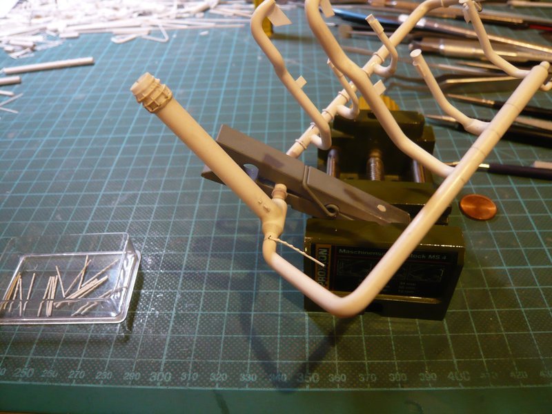
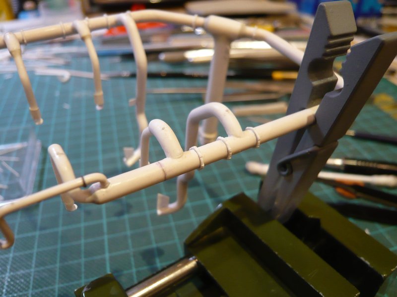
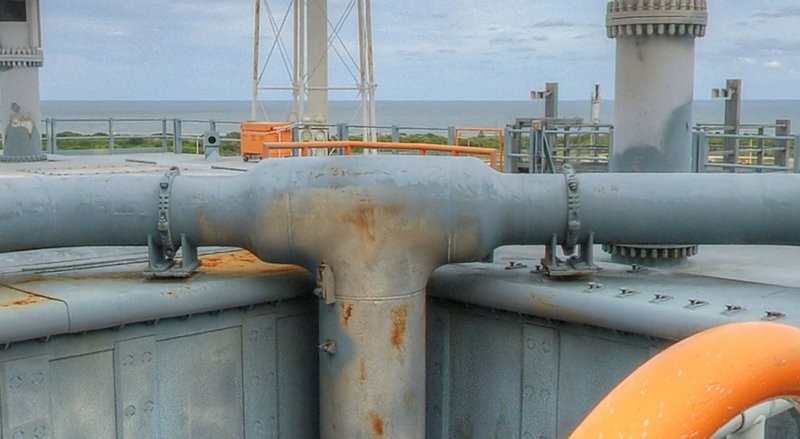
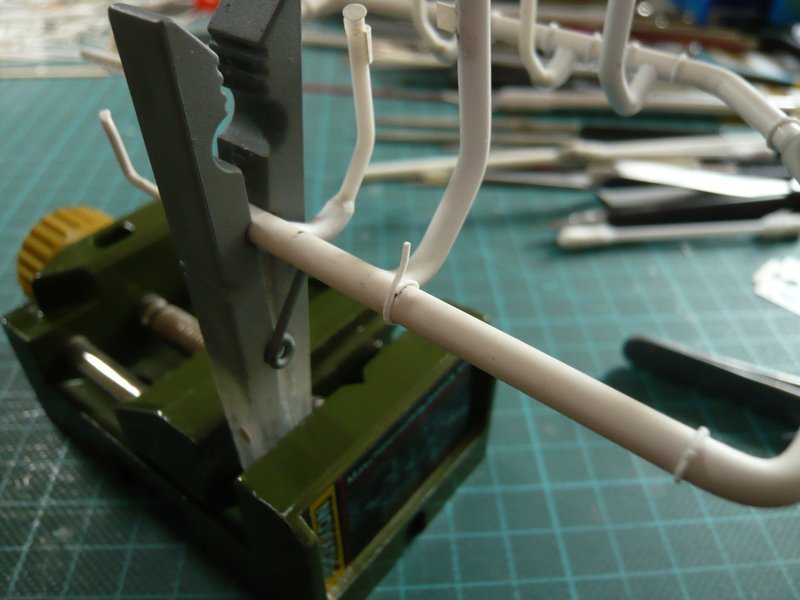
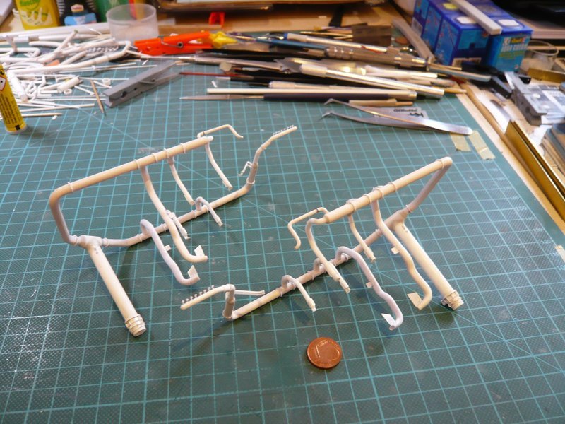
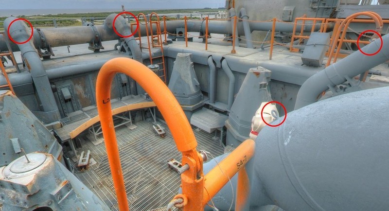
As can be seen in the picture, it started with four four-part clamping rings behind the TSM first, followed by five six-part rings.

At that I proceeded during gluing in such a way that I first glue only the first screw connection on the underside of the ring line with CA, and the remaining ring then stepwise until shortly in front of the last screw connection, where the end of the strip is glued fitting exactly connecting with the first screw connection after cutting off the overhang.

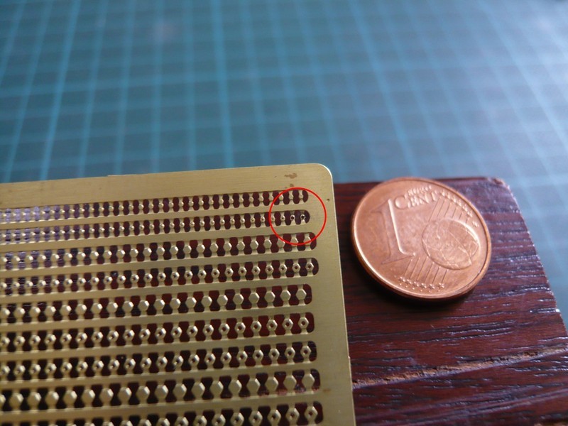
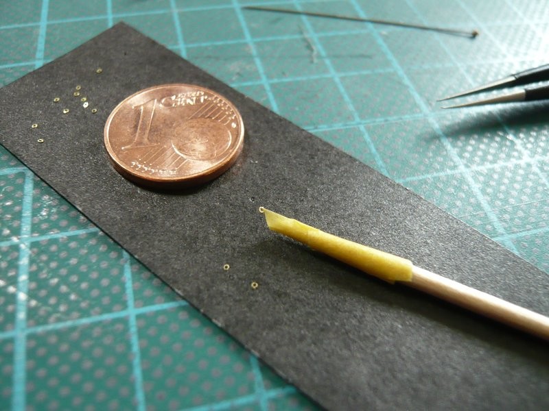
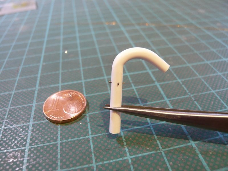
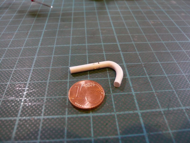
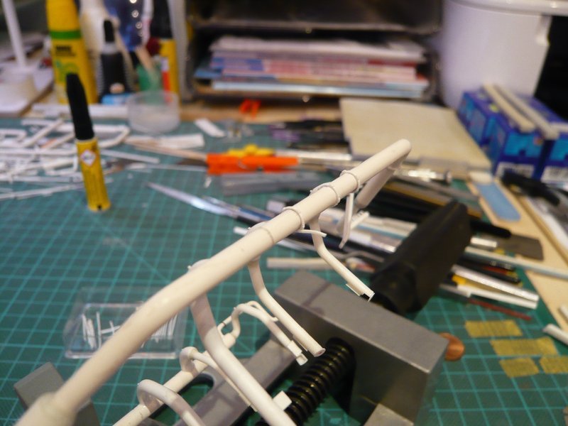
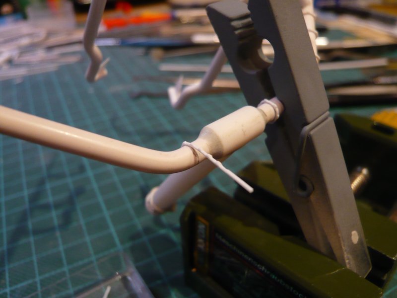
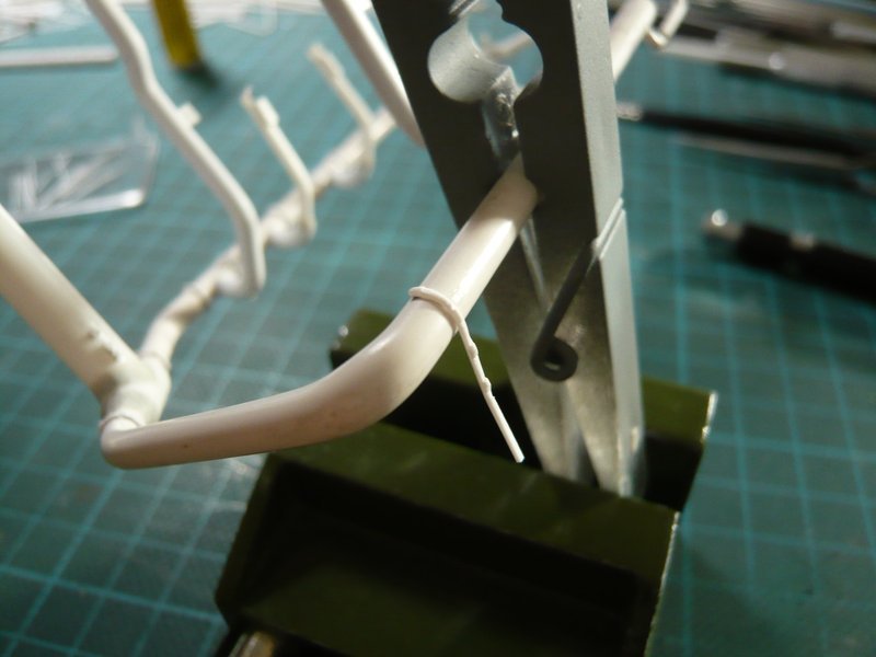
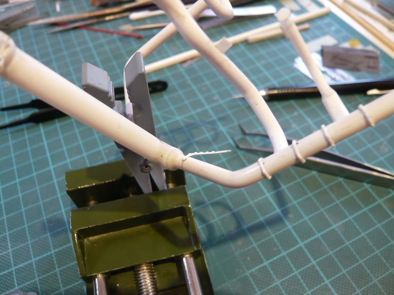
In order to allow the ring to be attached better when gluing, it is advantageous if the starting point behind the first screw connection is carefully pre-rounded. But already the start was a complete flop, because the first screw connection was broken off, which has surprised and frustrated me of course.

I can only explain it to myself, that the strip has been scratched too much during the chamfering of the screw connections and thus unfortunately had a predetermined breaking point.

This can happen already, but should not throw me off track, which is why I then went on still more cautiously.

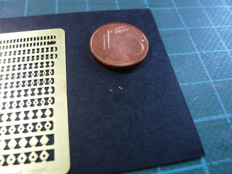
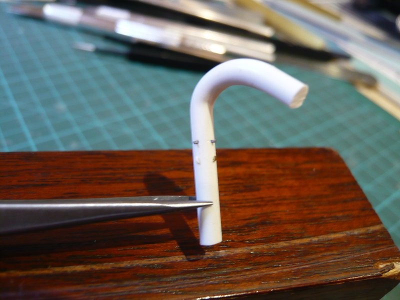
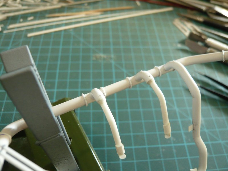
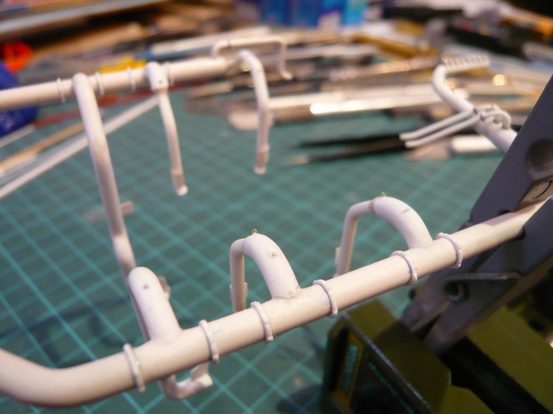
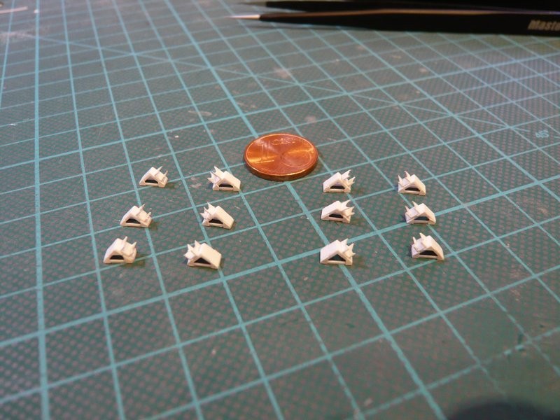
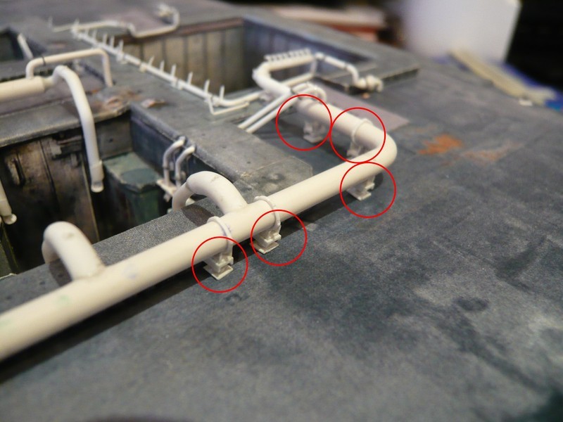
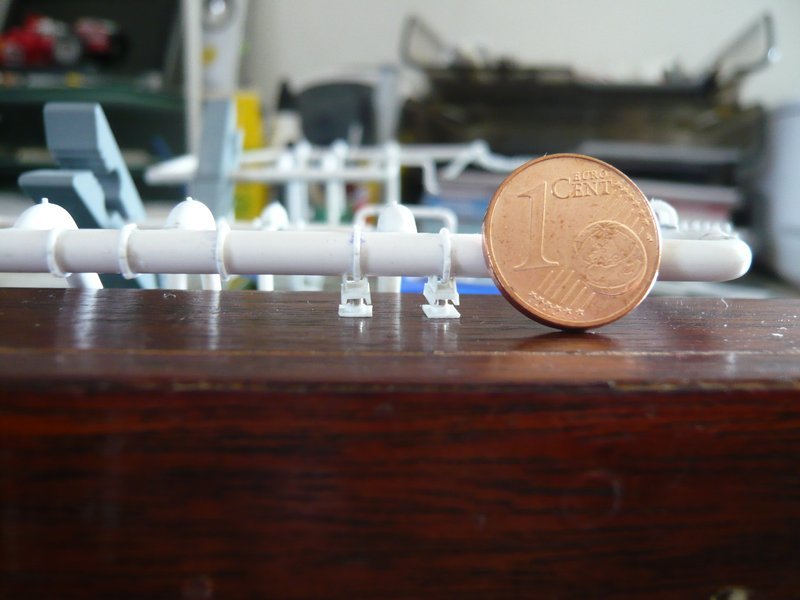
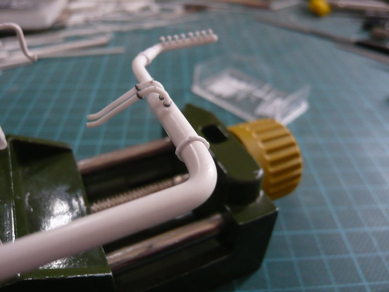
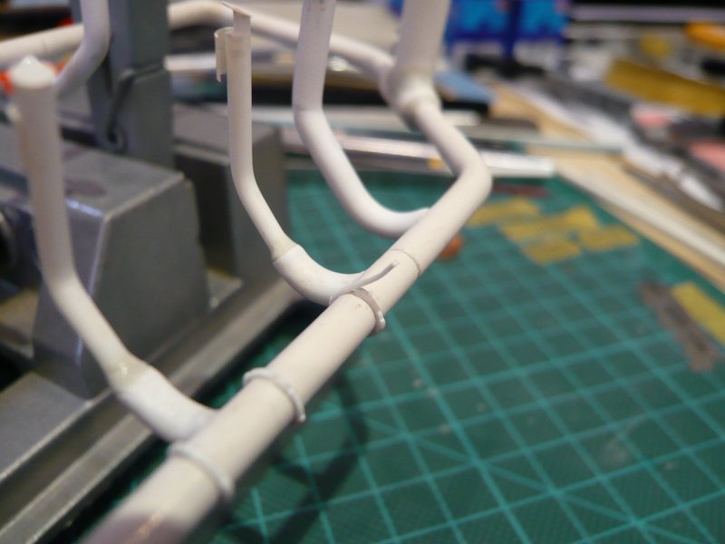
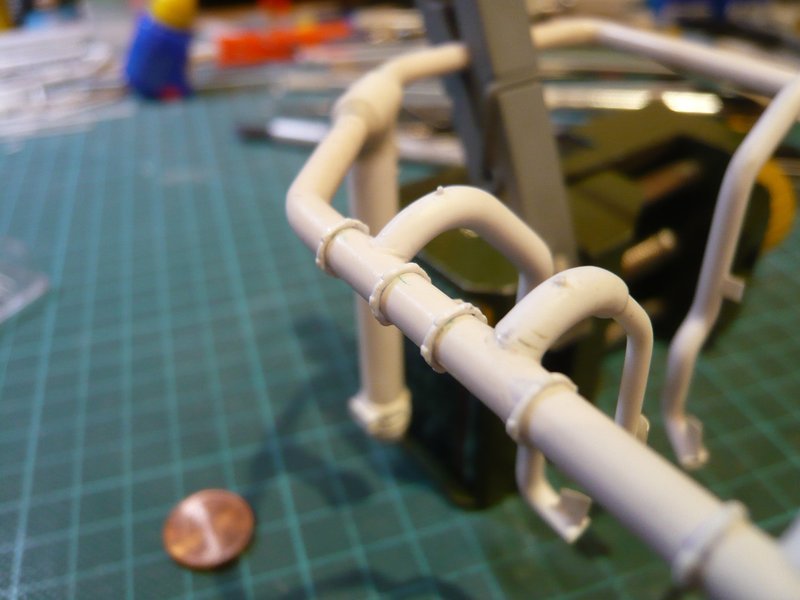
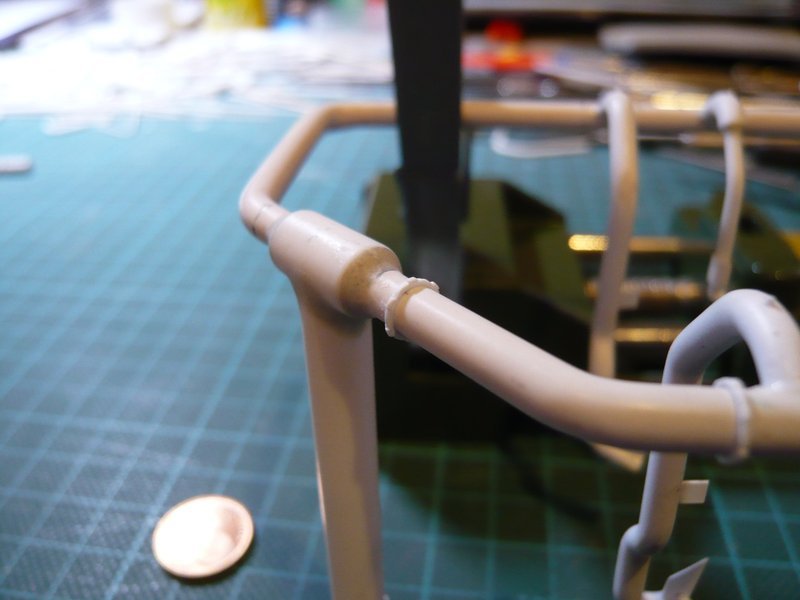
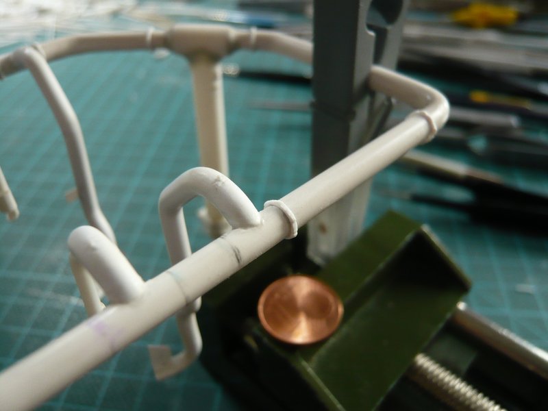
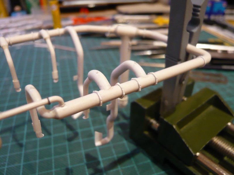
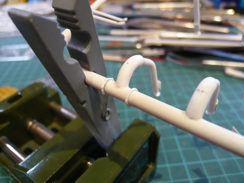
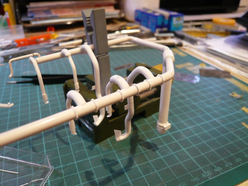
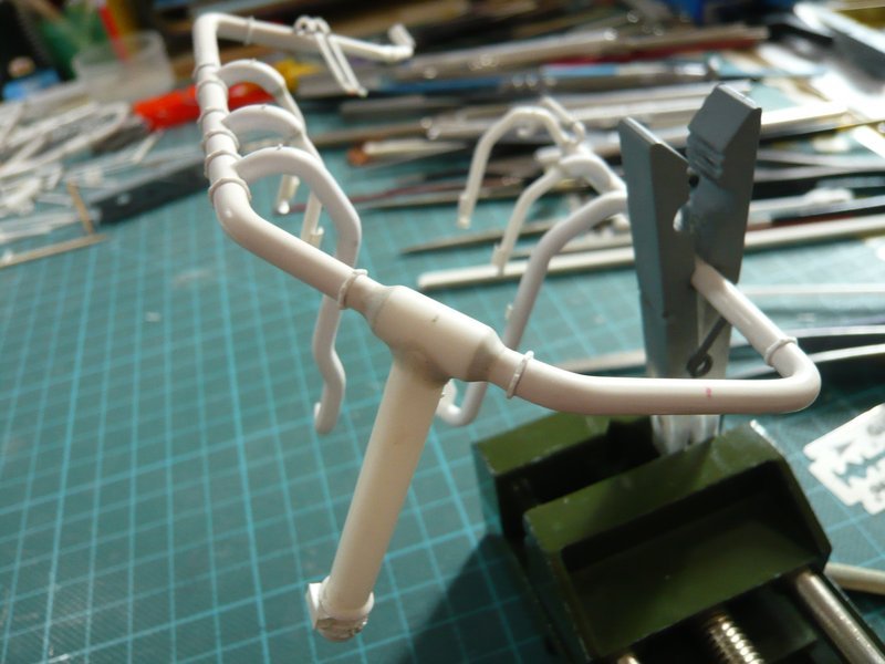
So I have glued the barely 1 mm long tiny screw connection and behind it then the remaining clamping ring, which still looks quite neat.

And in the same way followed the next two clamping rings, but unfortunately again not without slip-up.

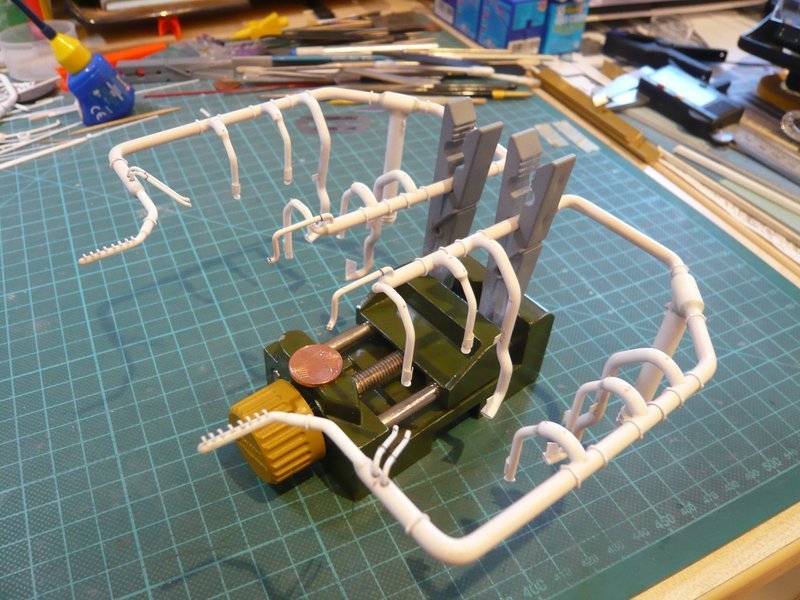
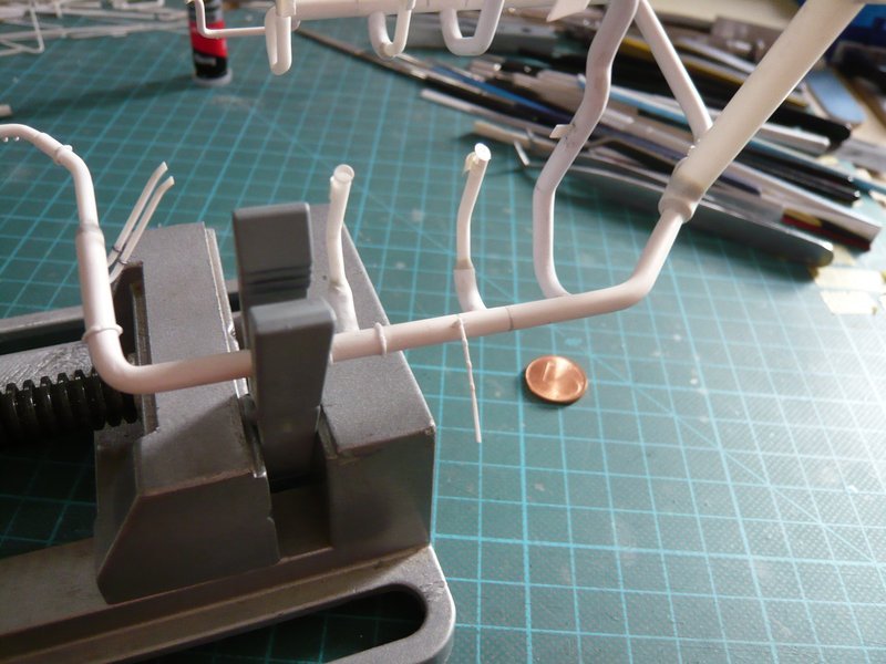
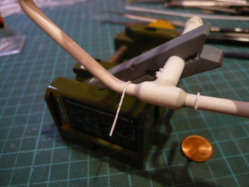
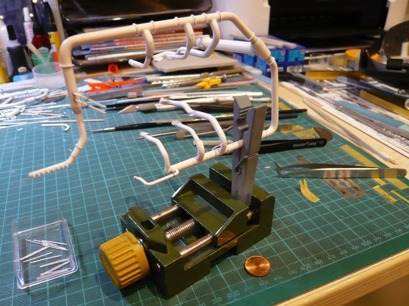
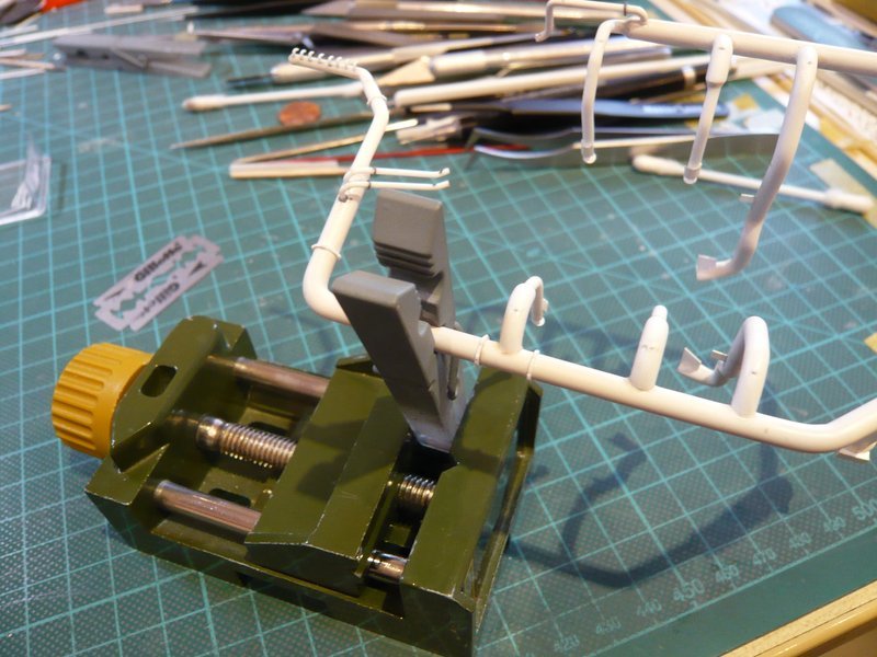
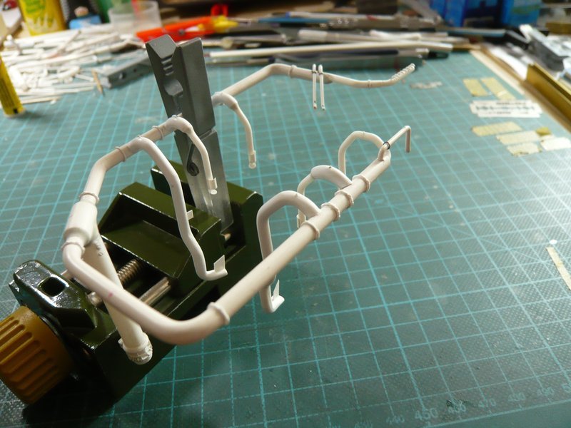
Because as I had already emphasized, one must clamp the ring line somehow, so that one has free hand, in order to position the clamping ring exactly and to press it smoothly.

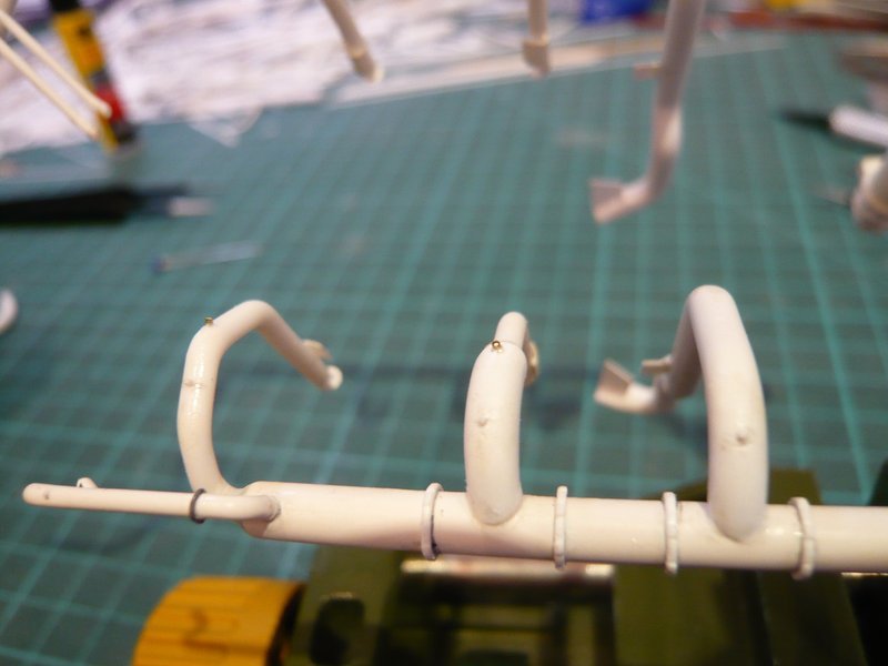
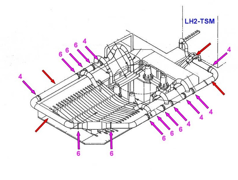
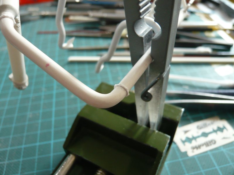
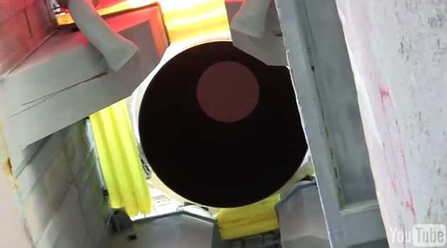
I had the ring line in my little vise already, but the inner 18’’ outlet layed obliquely at the vise, and during the careful pressure of the clamping ring there was suddenly a quiet click, at which I already suspected something bad …

And after clamping out of the ring line I got prompt the receipt, because the outlet had done its name all honor, and had gone out off the ring line, by which I was badly served and needed fresh air.

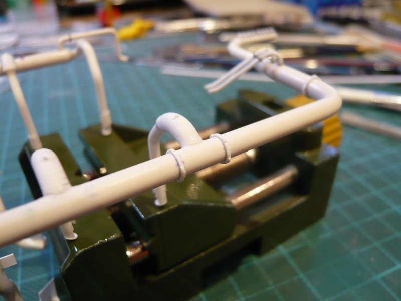
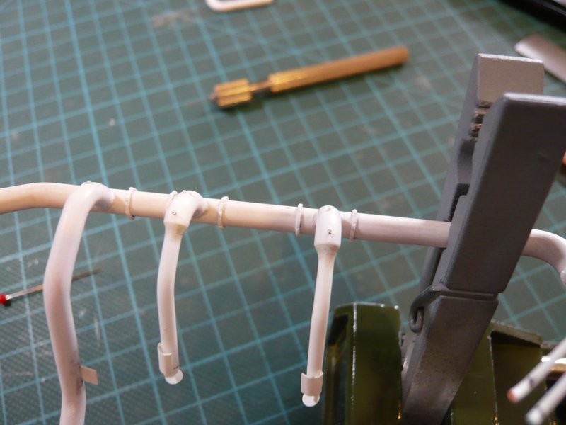
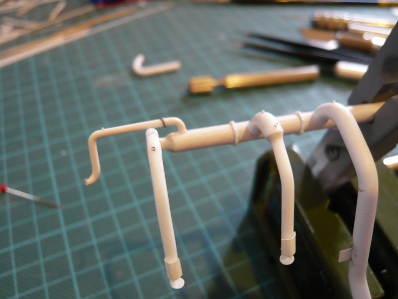
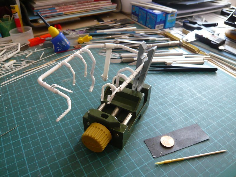
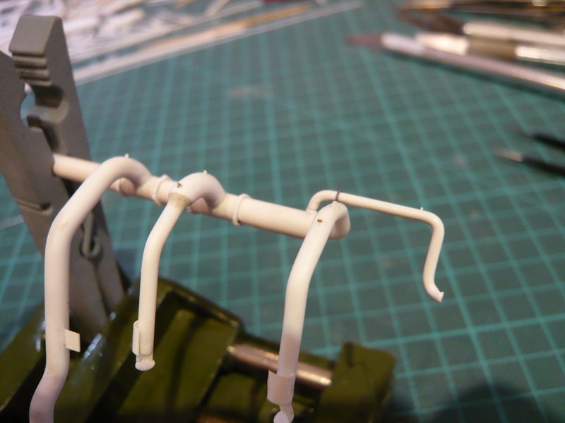
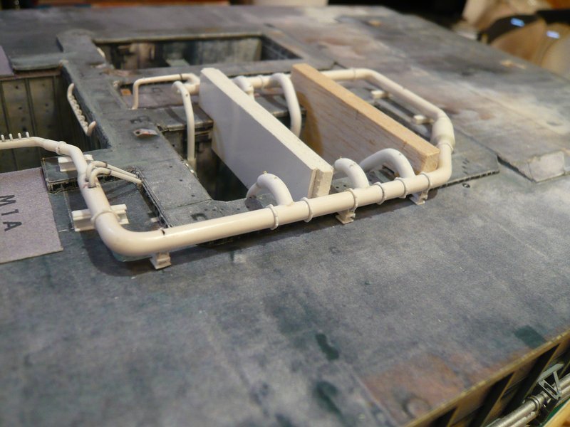
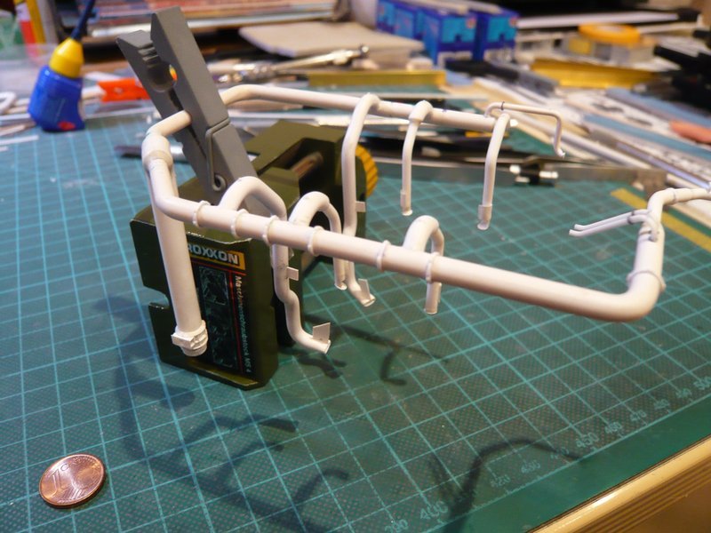
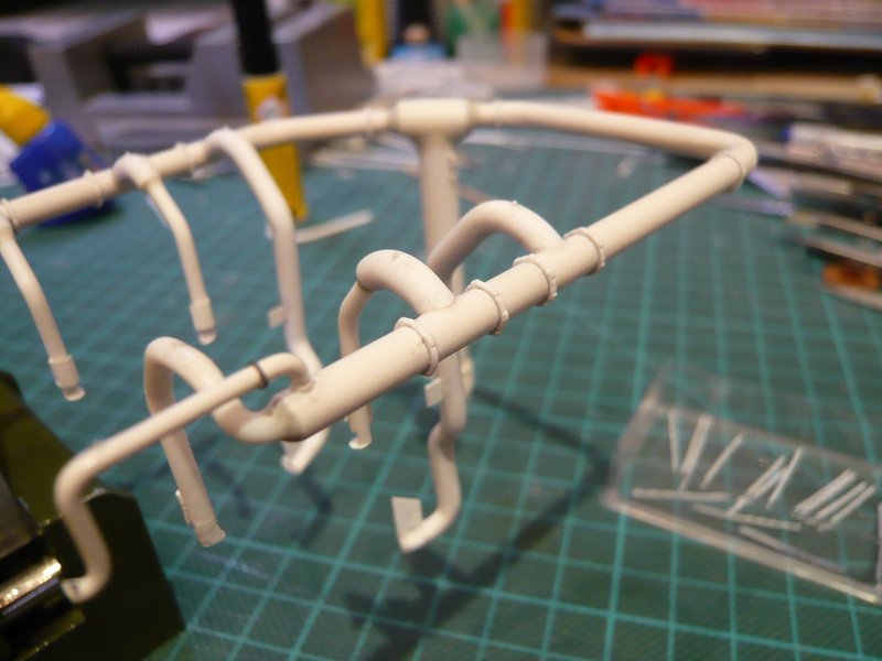
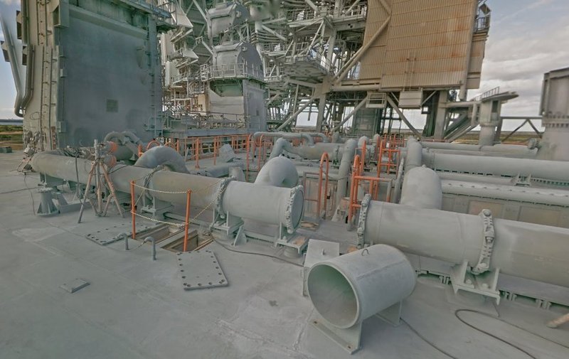
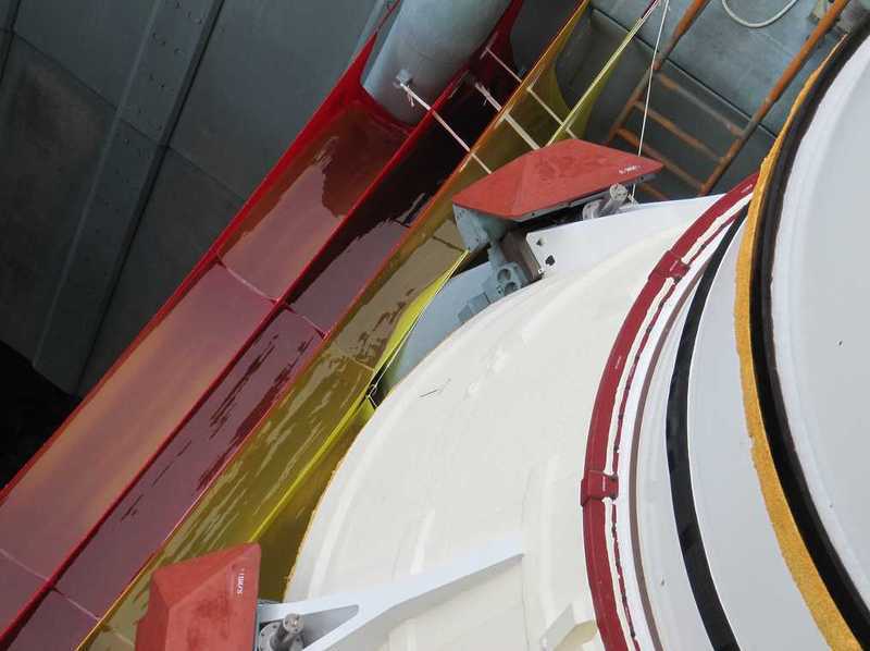
Afterwards, I have the ring line again in the SRB chamber inserted and the outlet again glued on. And this gave the opportunity to try out the supports just under the first clamping rings.

Now I just hope that the next clamping rings do not create similar difficulties and are good.

Hi Guys,

now I would like to give a short update again and have come up with a new and relatively flexible mounting technique.

In doing so, the ring line is received in the rear small opening of a clothespin, which is then clamped into the vice. In this opening, the ring is easy to turn, which makes the step-by-step CA gluing of the clamping rings enormously easier, since the rings can be reached optimally from all sides, without instantly to risk the breaking off of fragile parts somewhere.

At first the last four-part clamping ring still followed,

before it went on with the six-part clamping rings.

And the procedure becomes even more flexible, when the clothespin is clamped into my smaller Proxxon vice,

which I can also put on the side or place upright as required.

Although all this looks almost like a children’s game, the whole handling needs getting used to and is not completely harmless, as one quasi always juggles with raw eggs.

But gradually these sequences become more and more familiar too, and in my little box there are still a lot of clamping rings, whereby I almost have the impression that it would become no less but rather more.

But fortunately, this impression deceives and it goes slowly but surely forward, because all takes a lot of time.

2 Likes

Hello everybody,

and first of all, to all those who are still faithfully with this boring string-pulling, an extra Thank you for your patience, but now the finale is approaching inexorably.

After the first side has been completed, now the kink follows on which there are two six-part clamping rings on either side of the 36" inlet pipe, as can be seen here,


Source: nasatech.net

of which the former is already glued.

When searching for the most favorable clamping position for the stepwise gluing of the clamping rings, the line must be re-clamped several times.


On the following straight piece also a pipe support sits, but which has no clamping ring, as one can see in the first image.

And so it goes around the corner to the inner part of this ring line, where on the front and rear each a four-part clamping ring sits and in between them three six-part rings.


Source: nasatech.net

The faded markings had to be re-drawn several times.

And then finally the last mark was reached,

and this clamping ring also glued.

But then followed the total disillusion like a bolt from the blue, because that was nevertheless also a six-part clamping ring and no four-part ring … and I felt me like in the wrong movie.

But this can happen to you, when the concentration slows down in the evening and one should rather stop building and better go to sleep … what I’ve then also repentantly done.

Today I had to strip off the clamping ring heavy-heartedly which was replaced by a four-part.

Thereby the one ring line now is finally complete, and so tomorrow I can leap with fresh courage on the clamping rings at the ring line behind the LOX-TSM.

1 Like

Hello everybody,

now for the gluing of the first clamping rings on the ring line behind the LOX-TSM, and here is the overview of the arrangement of the 14 clamping rings with three four-part and 11 six-part rings.

As can be seen in the picture, it first started again with a four-part clamping ring behind the TSM, followed by a six-part and a four-part ring.

And then there are four six-part clamping rings on this strand.


Source: NASA (Google Street View)

Now half of the clamping rings on this ring line has been made, and my little box has now emptied quite nicely.

And now there remain only seven clamping rings on the other half of the ring line, which I also will still create.

That’s it for now.

1 Like

Long and slow repetitive work, but very much worth the effort to give it the real look.

Thanks John,

you hit the nail on the head again. This is a stressful fumbling, but unfortunately it has to be.

Luckily I have the patience of a saint and keep gritting my teeth.

1 Like

Hello everybody,

and now to the final spurt of the clamping ring chapter, which has occupied me long enough, where now these two six-part clamping rings on the SRB Blast Shield follow.


Source: nasatech.net

The arrangement of the following five clamping rings can be clearly seen in this picture (right strand), where behind the bow a six-part clamping ring is followed and then a four-part and three six-part rings.


Source: nasatech.net

Therewith this crazy chapter has finally been done, because this Sisyphus work of the tricky 28 clamping rings with a total of 150 screw connections was extremely exhausting and moreover very stressful.

And so I have now to relax and regenerate a little bit …

1 Like

Your precision to detail is…

2 Likes

OMG Mike,

Helppppp!!! - Alone in the details jungle …

I think I have to stop with these apparently shocking crazy details, but unfortunately I’m not finished yet.

So please buckle up.

2 Likes

Hello everybody,

for diversion from the monotony of these tiny strips, I’ve been busy with the Water Bags again.


Source: flickr.com (Jen Scheer)

On the task of this SSWS Sub-system I have already shortly reported earlier, and their scratch-building I will present later in an own chapter together with the Rainbirds.

On this older image from the STS-2 one can see that they were uniformly red during the early Shuttle missions and therefore also during STS-6.


Source: capcomespace.net

To warm up, I have looked around again and followed up some tiny details, which I noticed during the analysis of the clamping rings again and again.

These are, on the one hand, these rings on the anterior four outlets of both ring lines, which one can zoom within the panorama pic.


Source: nasatech.net

And then there are also several fastening hooks for the yellow water bags suspended around the SRB chambers (which were only used in later missions),


Source: youtube.com

which can be seen on these images,


Source: flickr.com (Jen Scheer)

and are marked here.


Source: nasatech.net

At first I have tried the rings and searched for a suitable insulating sleeve to cut off thin discs, just as I had made the transport rings on the covers of the Rainbirds.

While I was able to use a Ø 0,7 mm sleeve at that time, these rings had to be even smaller with Ø 0,4 mm, so I wanted to try it with my smallest insulating sleeve (Ø 0,5 mm), what certainly would be still a little too big.

And then I remembered PE Bolts & Nuts by ABER of different size, which I had bought earlier, which should be suitable, if a suitable diameter were among them.


Source: ABER

These are bolts and nuts in increments of 1,5 mm - 1,25 mm - 1,0 mm - 0,8 mm - 0,6 mm down to 0,4 mm, 
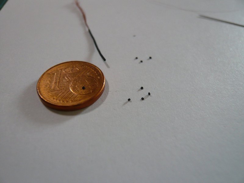
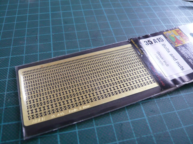
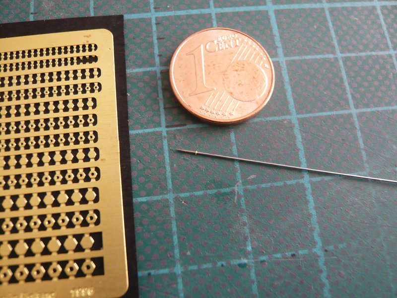
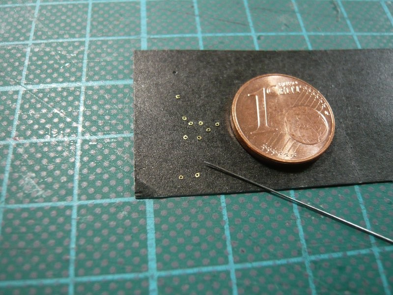
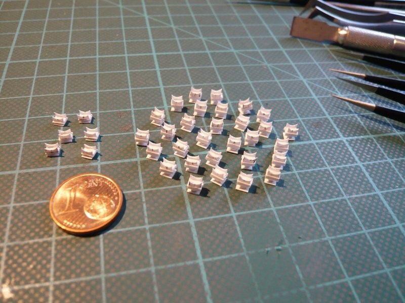
which however are so tiny that one can hardly see them in the last two rows. And from these nuts I then have drilled out the first two (right) with my smallest drill with Ø 0,25 mm,

and then cut out, which still should work out better.

And then I tried again with a smaller cutter.

But how to fix this tiny ring onto the 18’’ outlet, which is sitting on an Insect needle (Ø 0,25 mm), which can not be held in place with the most pointed tweezers.

That took a bit longer and was pure stress, which is why I almost wanted to give up.

For this I have dabbed a tiny CA droplet to the bow and then tried to place the ring, which was sitting on the tip of the needle, so carefully, and at the same time pull out the needle, so that both do not glue together.

But as you know I never give up and after several failed attempts, it actually worked well, and the result looks pretty well as I find.

But whether I should really do this effort, I do not know yet, and if so, then I would have to come up with a better gluing handling.

I am with you Manfred…don’t stop :grin:

Although, I wish someone could scans and clone all this wonderful detail you are doing. It will make my life easier and I will bless your name every time I look it over in my collection. :joy: But, I understand, no pain no gain as it’s not going to be His pain My gain with this here. :thinking:

Btw, great job in the macro otherwise that PE ring is hard to see in that pin or sowing needle.

1 Like

Excellent work Manfred… Problem with being that small and using the smallest amounts of CA glue, you need to be ultra careful not to keep knocking them off when it’s handled… Very clever technique though :+1:

1 Like

Thanks Mike and John for your nice compliments.

The smaller the details are, the more difficult their handling becomes, especially when gluing.

But there is a solution for everything. Nothing is impossible!

1 Like

Hello everybody,

in the meantime, I have a tough time of it with the rings, because I do not give up so quickly.

Here are some more or less well done rings together with the needle (Ø 0,25 mm), which I can safely forget in order to hold the rings when gluing.

On the macros, these midgets still look quite grippy, therefore here for the relativization a shot from normal sitting position.

And therefore the handling is only possible with the headset-magnifying glass, of course.

And also the solution with the Pattafix tip on the toothpick is not the yellow of the egg, because sometimes tiny remnants of Pattafix stick to the ring, which can be removed only badly, without the ring thereby perhaps tear off again.

Therefore using a toothpick with a tip made of a masking tape is much more suitable for this purpose, with which the ring can be gently taken up, in order to be able to deposit it over the CA droplet on the outlet arc, where it should then glue.

And this technique has then worked well with the following ring, as one can see here.

And so it went on with the two rings at the outlets on the inside of the ring line (right circles) behind the LOX-TSM,


Source: nasatech.net

which can be seen here.

And strengthened by this partial success, I now also want to equip the outlets on the ring line behind the LH2-TSM with these rings.

Well, and then I’ve experimented with the hooks for the lateral Water Bags.


Source: nasatech.net

To do this, I have initially put simple plugs of lead wire (Ø 0,3 mm) in pre-drilled holes on a dummy.

And these are two hooks, to the left of my thinnest rods (Ø 0,3 mm) and right of brass wire (Ø 0,3 mm),

which are still too high with 1 mm and have to shrink to half.

Since I’m not enthusiastic about the result, I have to outbrake myself now and will cancel these hook tests. In addition, the fragile outlets could break off during pre-drilling, what I would not risk at all.

With these details, I am moving in the border area of what is doable with reasonable effort, because they are so tiny that one can hardly recognize them, which is why the effort is not worthwhile.

2 Likes

Hello friends of the rings,

although this fiddling is getting slowly but surely on my nerves too, I have still to pull through the four rings at the outlets of the other ring line, earlier I give no rest.

But that was once again a hard patience test, especially since the handling while gluing these tiny rings even with my cool tape tweezers was really stressful, because it didn’t release the rings occasionally at the crucial moment.

But then the two rings on the outside of the ring line were finally done.

But even taking photographs of this bulky pipe skeleton is not a simple matter, and it is also quite time-consuming, if one wants to represent the details sharp, because it depends on a favorable perspective as well as the light conditions.

And since for good macros one has to approach as close as possible, one must be careful, in order not to bump with the Digicam somewhere and even to damage.

And so to the outlets on the inside of the ring line,

here something more from the proximity.

Now, both ring lines are finally finished and could be painted.

Of the rings one can hardly see anything from this perspective, but they are completed, wherewith this chapter is finally finished.

So far for today.

2 Likes

Hello everybody,

after all the clamping rings have been installed now, the question now arises about the further procedure with regard to painting (Airbrush) of the ring lines, about which I have been tinkering for a while.

I am not quite sure whether I should glue the supports before painting (possibly with MEK?), or whether I paint all the supports and the ring lines first separately, and then glue the supports …

Here is once more an elder image with all the supports, but still without clamping rings.

With the clamping rings, the interspaces there will inevitably become even narrower.

To glue the supports previously and then completely paint the whole skeleton with all the supports would certainly be the less expensive method. However, I have doubts whether one reaches with the Airbrush jet into the small interstices between the sickle holders and clamping rings, or whether they could possibly clogged, which of course should not happen.

For this I have here a macro image of the place conditions between the ring line and the supports, whereby the distances between the sickle holders are about 1,5 mm, between which the clamping rings (0,5 mm) sit, whereby one should not be deceived by the real proportion.

Otherwise, I would have to airbrush the supports separately, possibly only from above, and the ring line with the clamping rings at least at the bottom, then gluing the supports and airbrushing once more all together …

So all in all a pretty tricky decision to a guaranteed stressful procedure, that I must meet now, which is why I am curious what you mean, or what you would advise me …

3 Likes

Fantastic progress Manfred! My usual policy is to glue everything that needs to be glued first, before priming & painting. When that makes getting good air-brush coverage difficult or impossible, a nice soft/sable brush gets into those awkward areas. In fact I would consider hand-brushing all pipework assemblies, and plan to do it in two thin-ish coats to eliminate any brush marks.

Thanks Tim for your nice compliment and tips of experience!

With paintworking one can mess up a lot, which is why it shouldn’t happen. Therefore I will first prime the skeletons all around with an airbrush in several steps and then airbrush it in the same way. For this the airbrush gun has to play along and must not clog.

In the meantime I had thought over, that it would certainly be difficult to remove the paint on these fragile sickle holders, especially since the contact points should be clean for a good adhesive bond.

And that would mean that the fragile sickle holders would have to be sanded gently, which would presumably not happen without breakages.

But I’ve already considered whether I should not paint the spaces between the sickle holders with a fine brush by hand …

I have not painted anything with Airbrush for a long time, which is why I’m simply unsure whether such horizontal surfaces below the ring line would get enough paint. Furthermore the paint application has to be well dosed, which is why several thin layers are advisable and too much paint at one go should be avoided.

Because I would bite me in the tush if I would spoil my painstakingly scratched details by an unclean varnishing …

1 Like

Hello everybody,

and because we have dealt with breakages, of which I had to complain already some at the ring line outlets, without damage the last action with the clamping rings unfortunately had not ended.

On closer inspection, I have noticed unfortunately that the small nipples on the outer two 6’’ outlets behind the TSMs after the felt 100.000 twists and turns when clamping the ring lines must have been broken, which I had not noticed so far.

That is why, for a change, cosmetic operations were announced today, because something like that bothers me, even though it would hardly be noticed by somebody else’s.

These surgeries are, however, rather delicate, since the outlets are only thin round bars (Ø 1 mm), into which still thinner rods (0,3 mm) have been glued as nipples. That is why I have first carefully sanded off the remaining stumps and then still more cautiously drilled small holes with Ø 0,3 mm, but for which I first had to think on a clever clamping condition of the ring line for a stable support.

Seek and you shall find, and here the nipple rod is already glued again with a little overhang, which now only needs to be shortened accordingly, what but also does not so easily go out of cupped hands.

For the cutting off the overhang then a different support had to be found and to be newly clamped again,

so that the rod also has a stable support and can not break off.

But that worked out well,

as one can see here.

And the same surgery then synonymous still at the other ring line, as before.

And so the damages have been remedied again.

2 Likes

Hello everybody,

in the last few days I have finally brought myself to start with the gluing of the Pipe Supports under the ring line behind the LOX-TSM, for which the already announced removal of the rear SRB Supports was necessary.

Since I can carry out the gluing of the supports only step by step, in order to be able to check their seat, I have to remove the ring line now and then, and because I did not want to risk anything, I have removed the disruptive rear SRB Supports.

For gluing of the pipe supports, the ring line was then introduced again and its exact seat fixed with the spacers. After that, I tried as a first variant the gluing with MEK and have initially positioned and aligned only three supports under the ring line, as well as dabbed the contact points of the sickle holders on the outer side carefully with a fine brush with MEK, which should be sufficient for a first hold.

And as one can see in this picture, that was actually already sufficient.

Since in the bracket-holder I can reach now the remaining contact places of the sickle holders from all sides, I can now also glue them completely.
And so it can then gradually go on with the next supports.

2 Likes