Nice work buddy. This is a complicated structure so I would paint and weather this before gluing it the structure. Just don’t get any paint on the bottom attachment point. It will make things a lot easier but you are the master of this and I am sure it will be approach in well thought manner.
1 Like
Thanks Mike, ![]()
I’ll do what I imagine, which is mostly a usable solution! 
![]()
1 Like
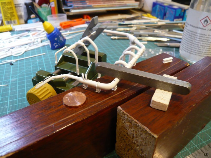
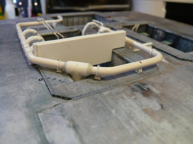
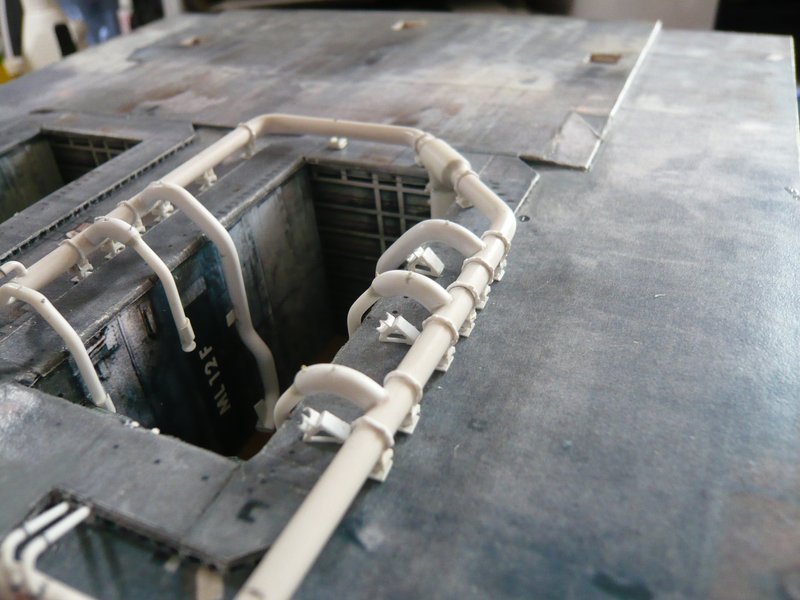
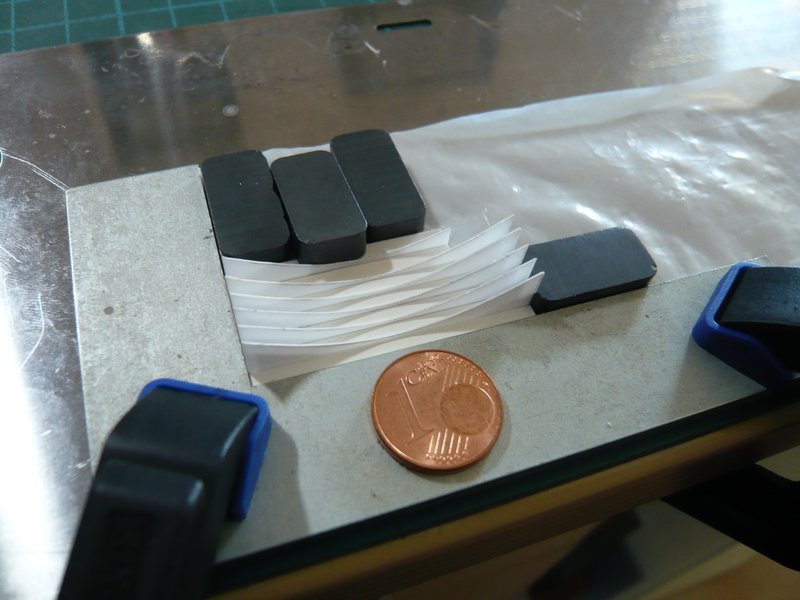
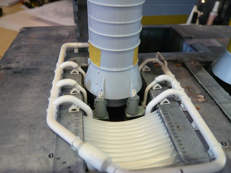
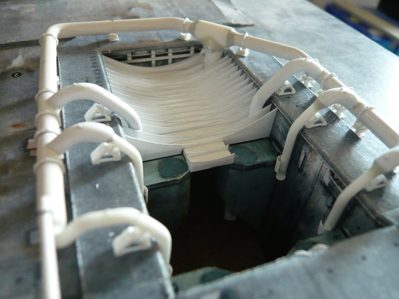
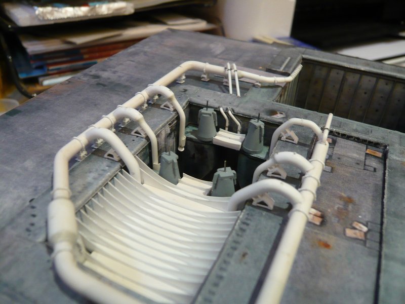
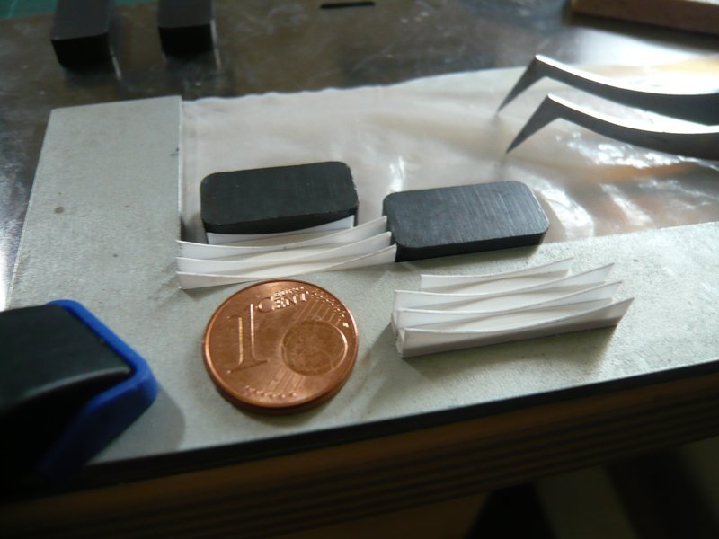
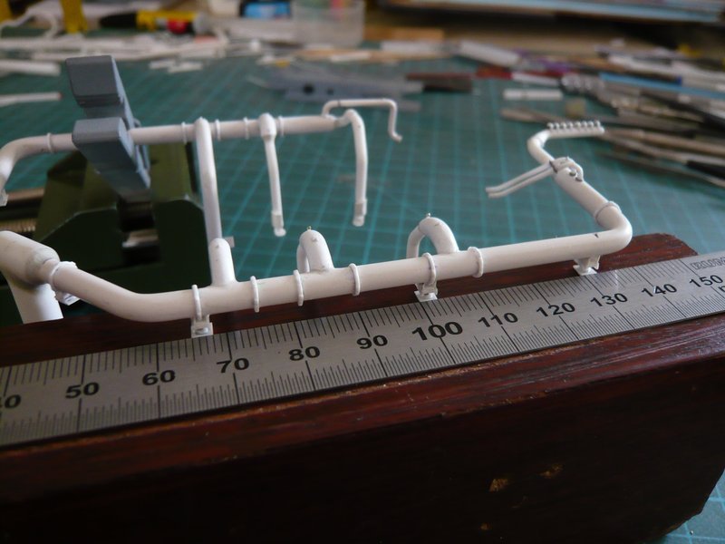
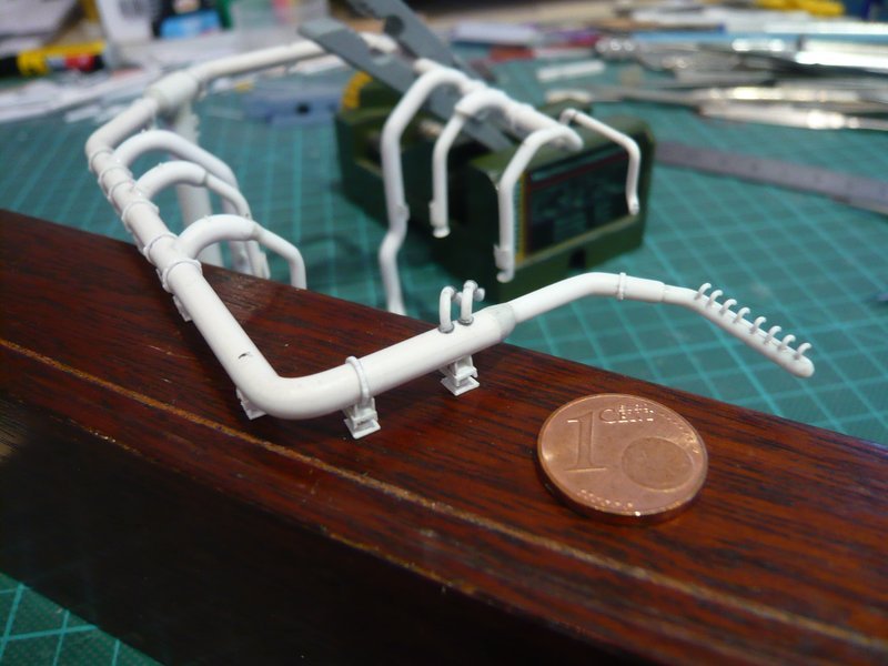
Hi all together,
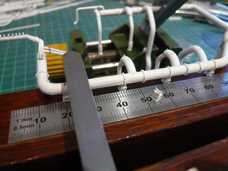
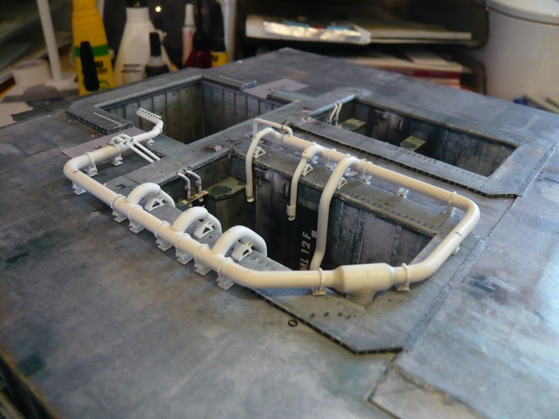
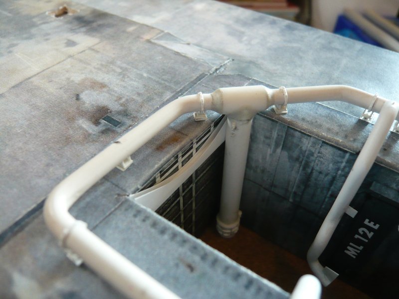
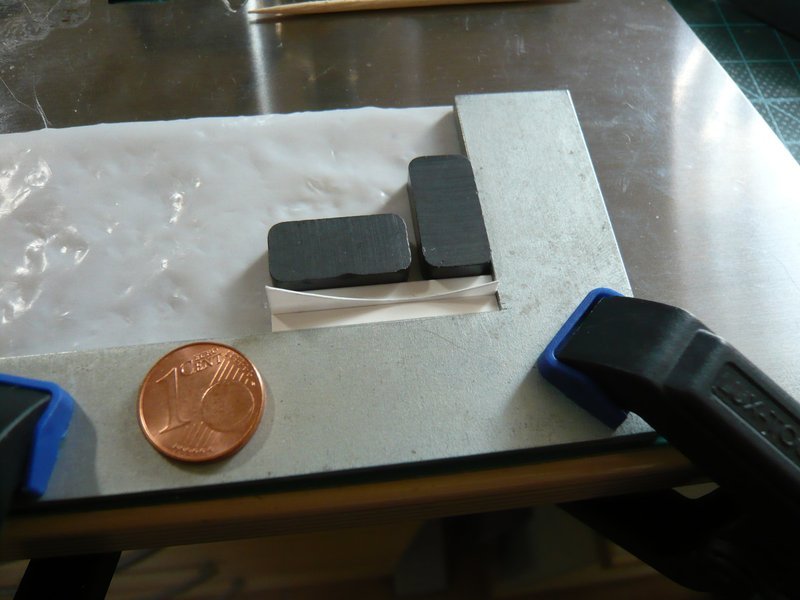
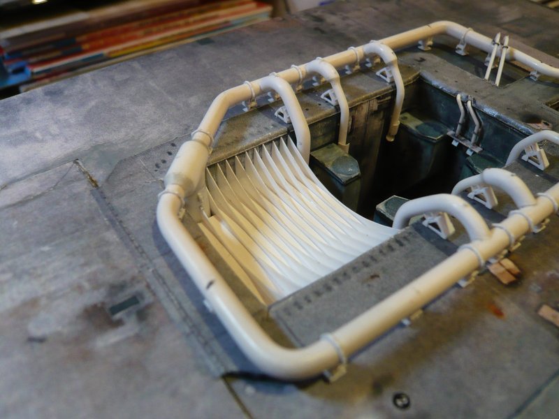
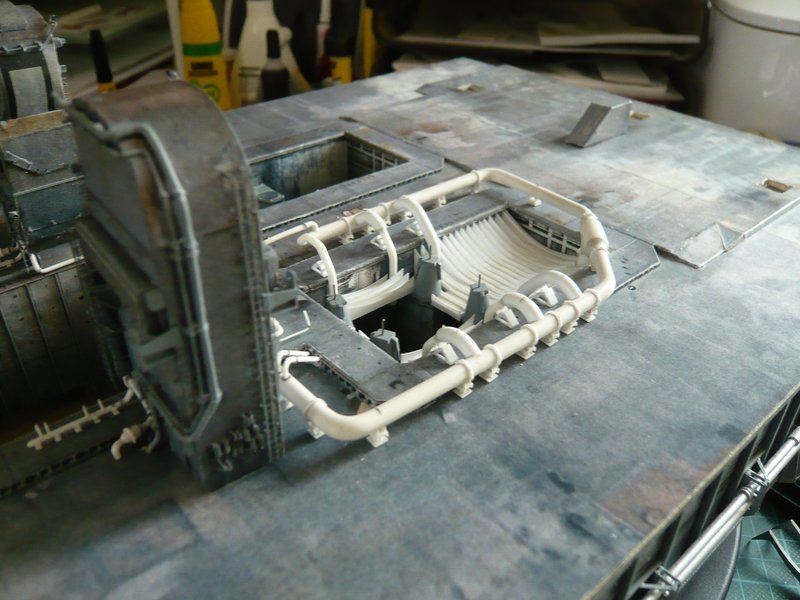
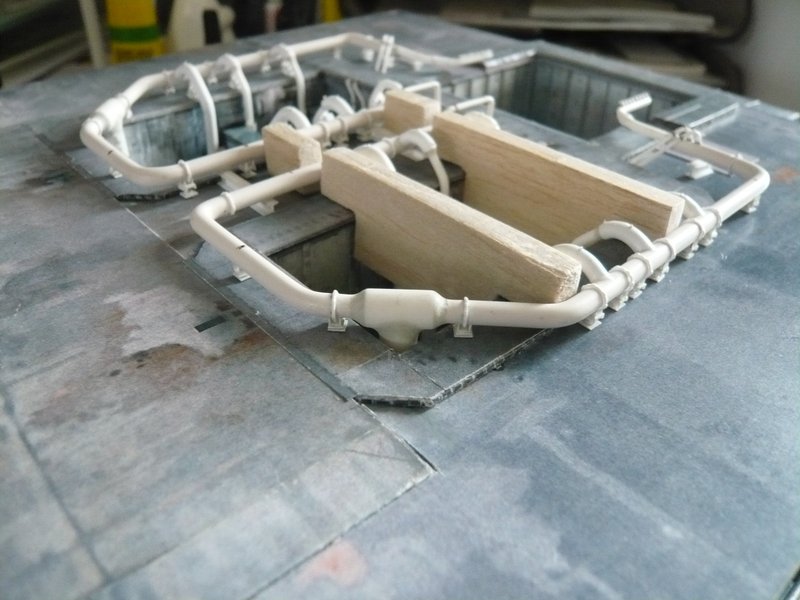
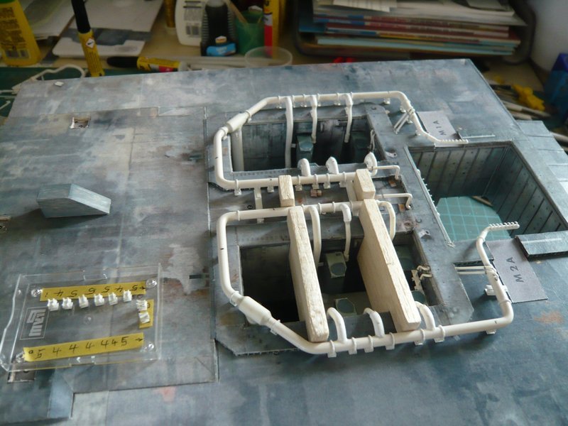
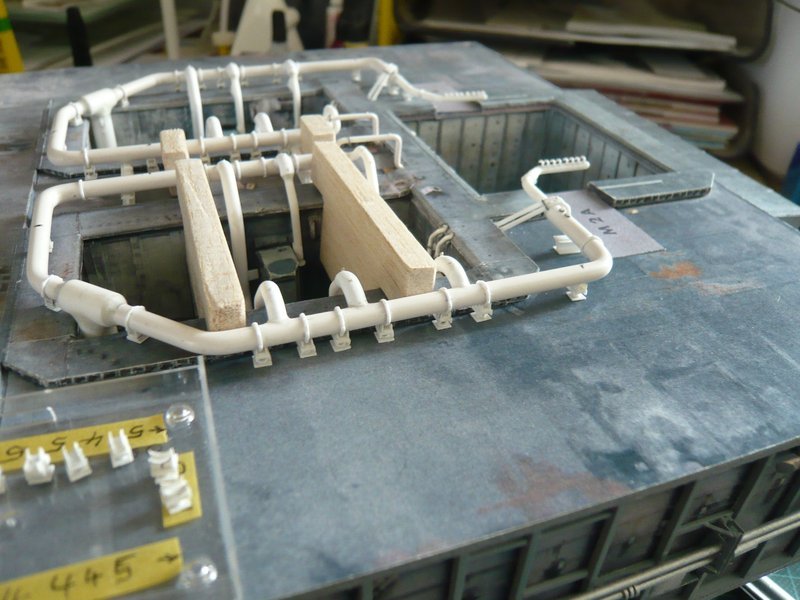
for the gluing of the next Pipe Supports I used again my approved bracket in the mini vise, which is best suited for this. ![]()
With this I have much more freedom of movement for the assembly and can adjust the position of the ring line so that the already attached three Supports lay flat on the support block and I can push the next supports below the line by slightly raising and arbitrarily align. ![]()
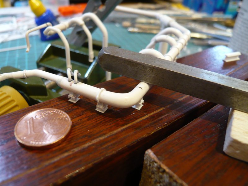
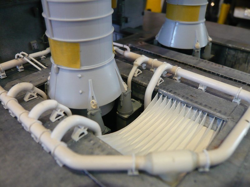
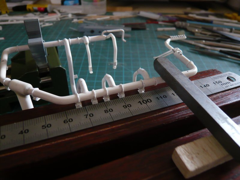
Then I also modified the gluing technique, whereby I carefully dab the normal Revell plastic glue onto the sickle holders with a acupuncture needle, then push the support under the raised ring line and then lower it. This allows for even smaller position corrections until the support sits in the right place. After that, the ring line is still weighted down, so that it can be fixed firmly on the spot. ![]()
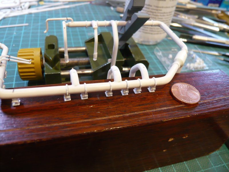
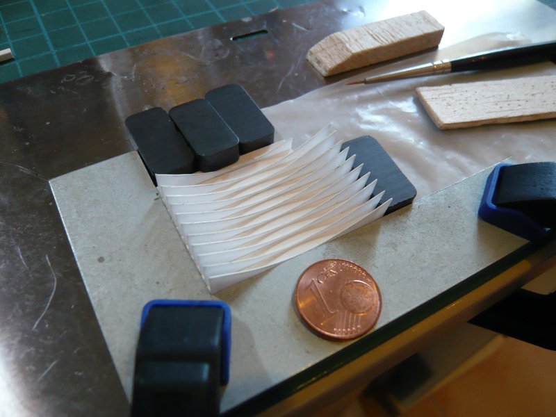
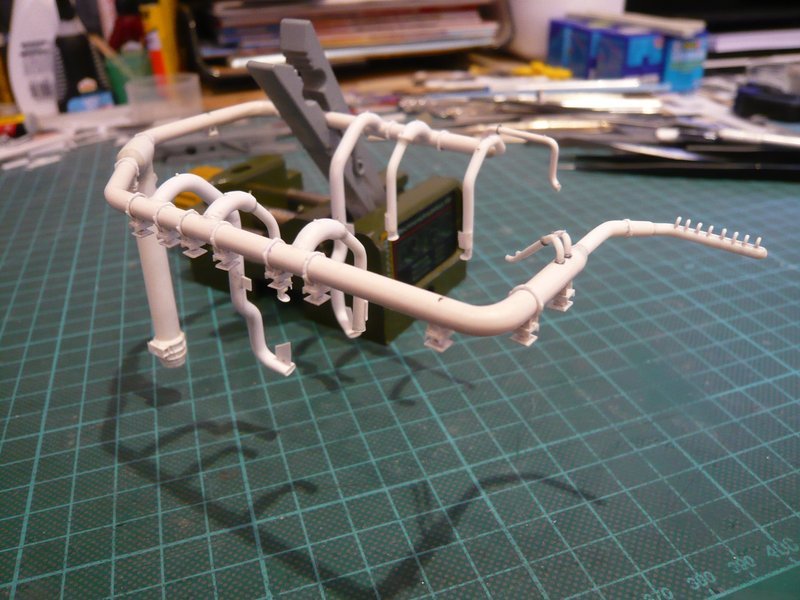
Then I can then take the mini vice with clamped ring line in the hand and stabilize the sickle holders also still from inside and outside with MEK, which should give them the final hold. ![]()
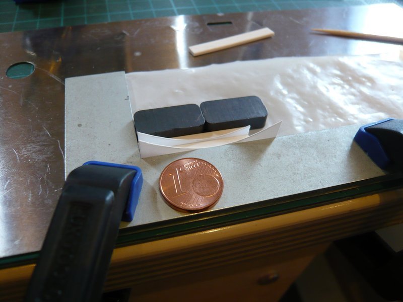
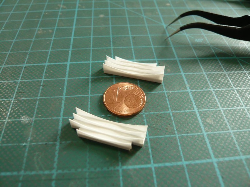
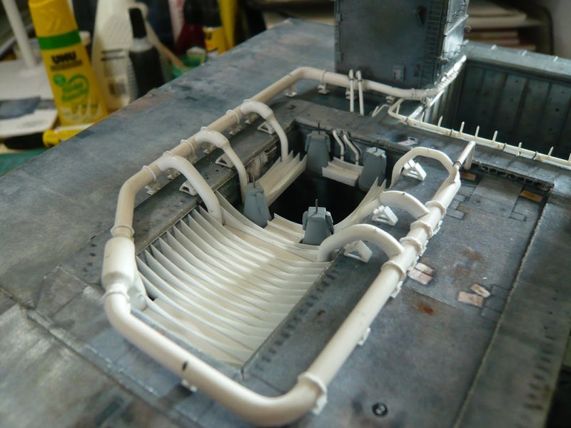
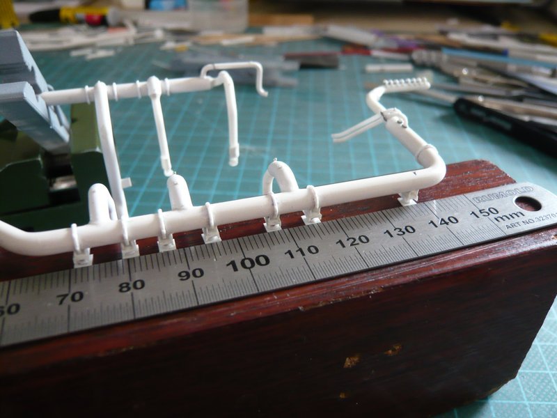
And this technique I have here exercised with the two Supports behind the corner bow, which also worked great. ![]()
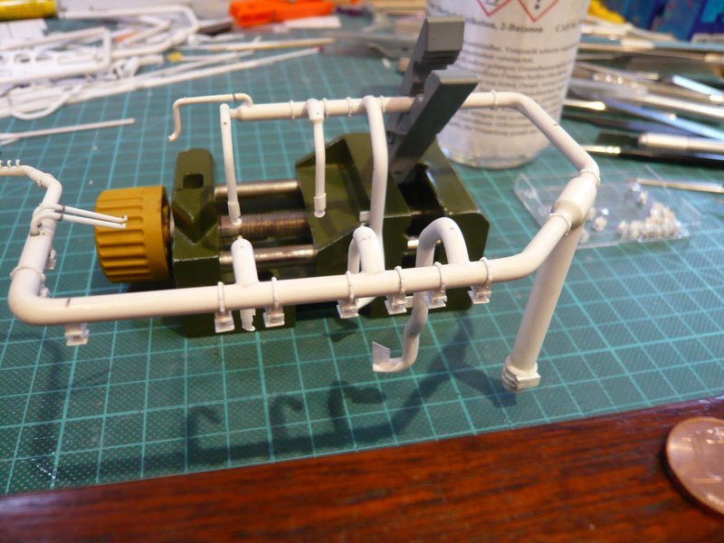
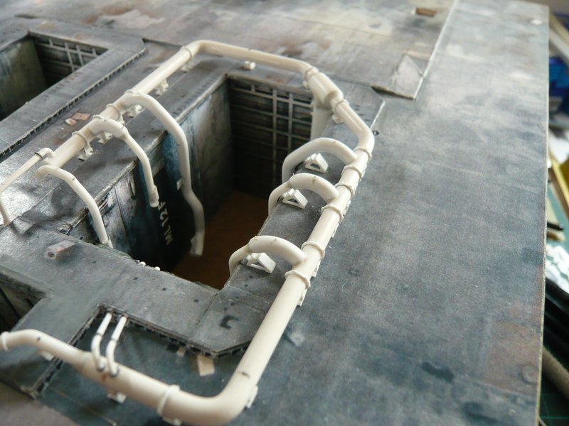
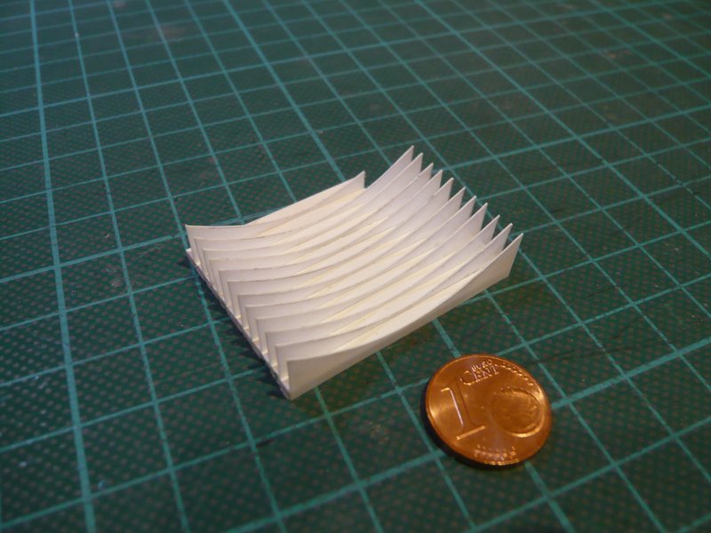
And in the same way it went on down the straight line.
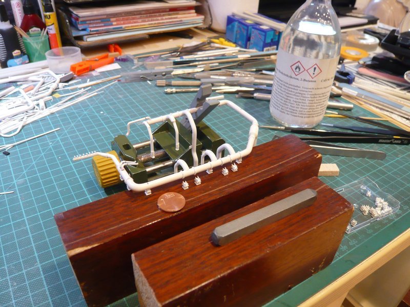
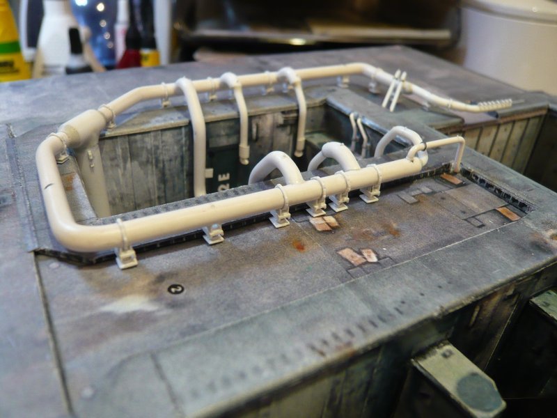
And now they hang in rank and file and look great. ![]()
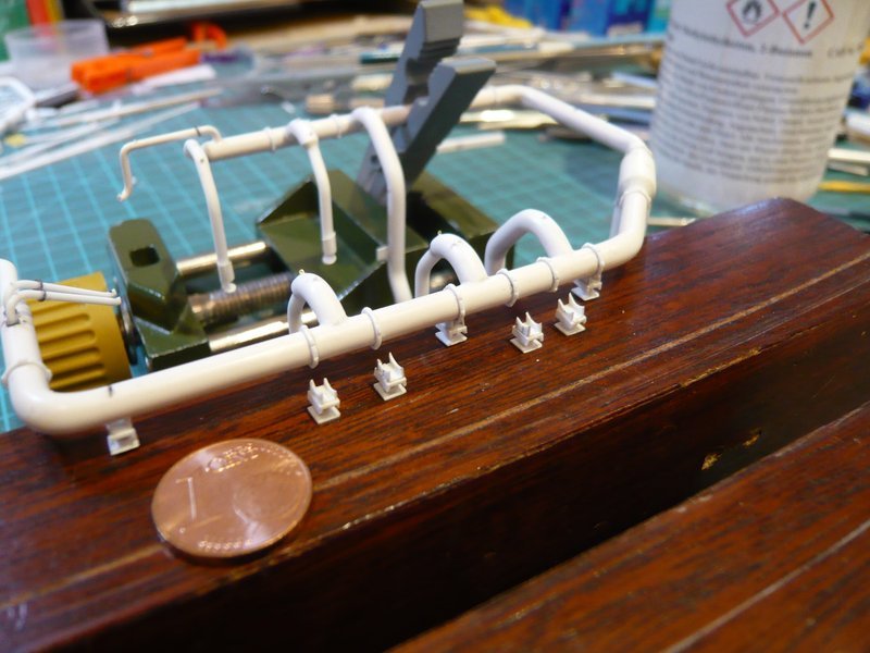
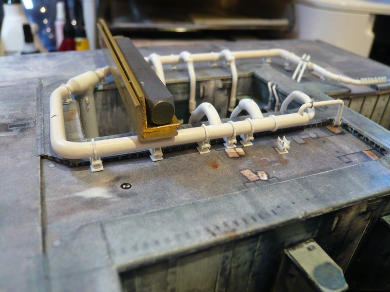
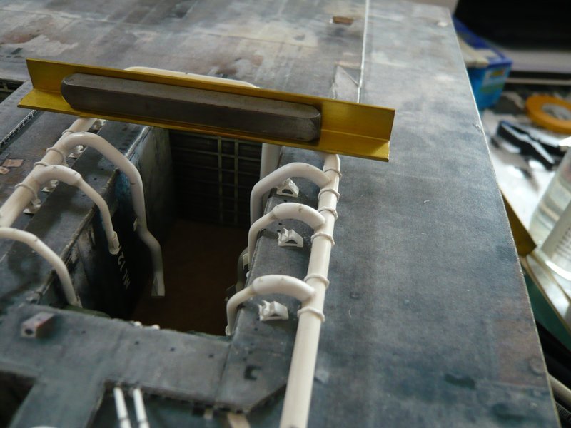
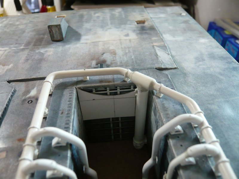
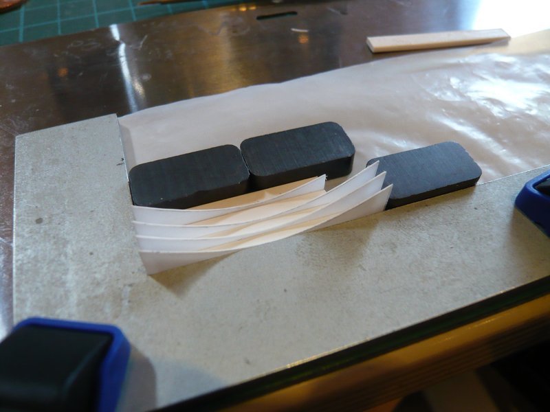
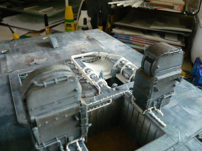
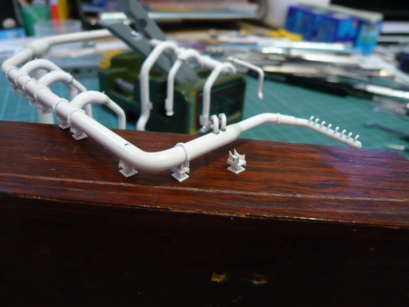
Then came the three flatter supports sitting on the Blast Shield, which I have glued with inserted ring line.
And finally, I have glued the small support under the 16’’ rejuvenation behind the LOX-TSM, which has only one sickle holder.
So I want to let it go for today. ![]()
![]()
3 Likes
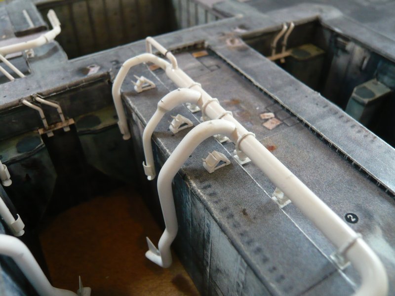
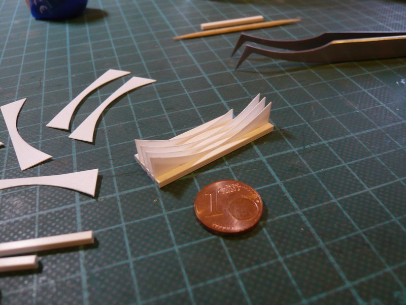
Hello everybody,
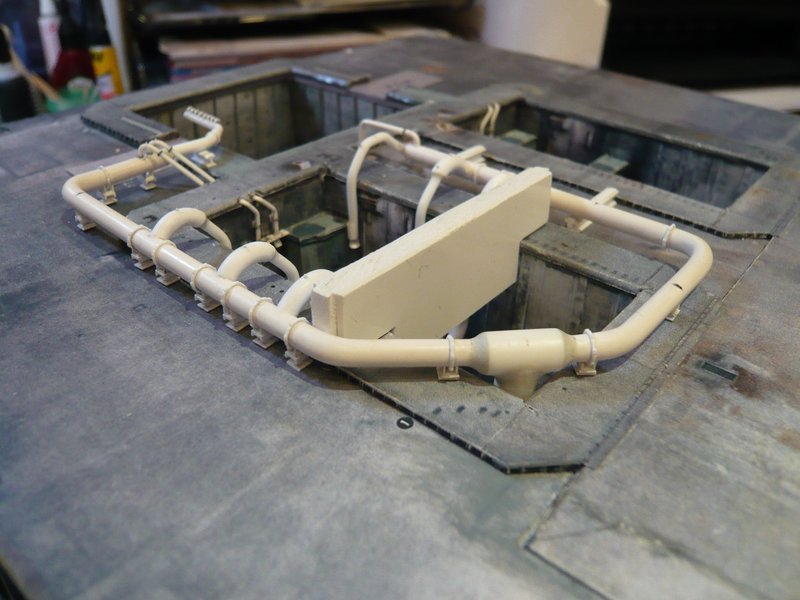
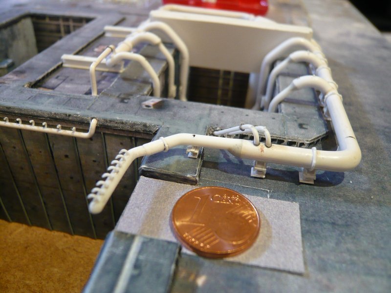
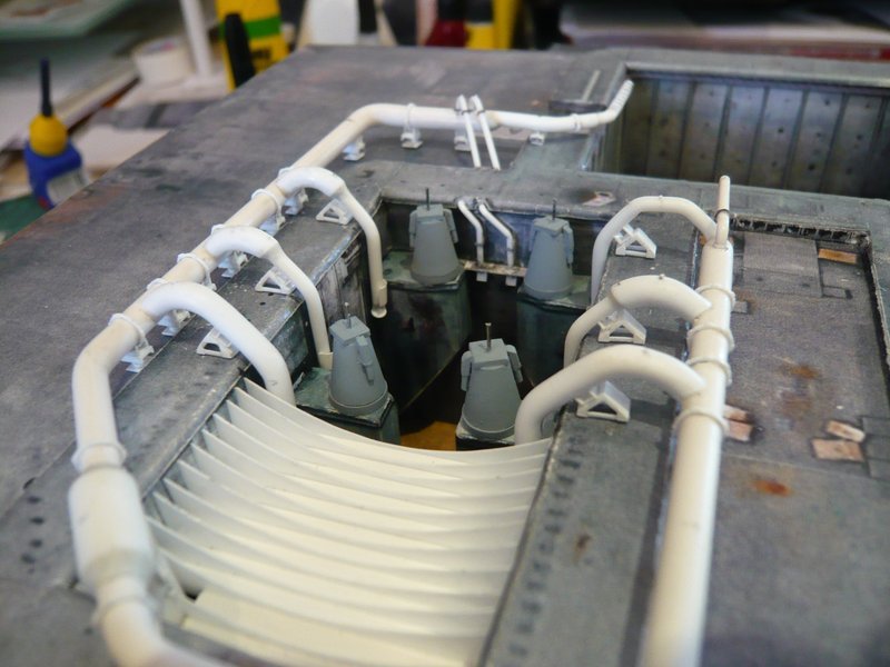
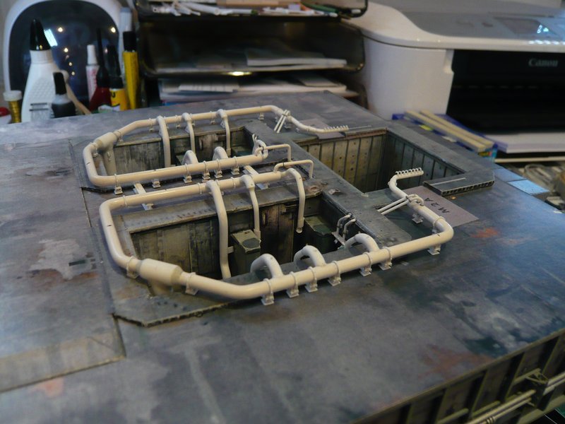
today I want only present a few pictures about the gluing of the six Pipe Supports on the inside of the ring line behind the LOX-TSM, which took place in the same way. ![]()
And next it will go on with the gluing of the first six Triangular Supports (left) at the outlets of this ring line,
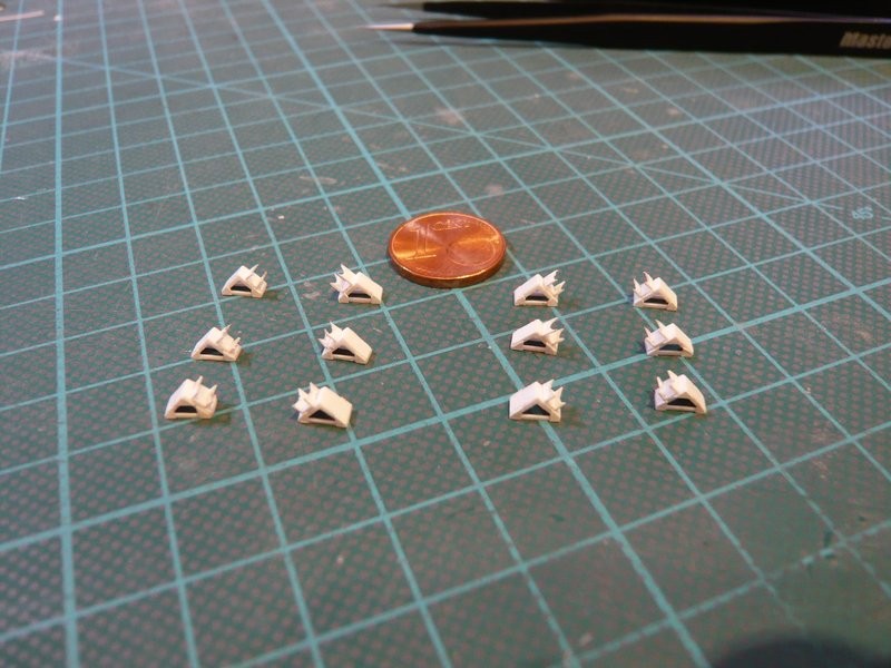
which hopefully will work similarly well. ![]()
![]()
2 Likes
Hello folks,
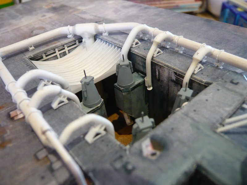
as hoped for, the gluing of the first three triangular supports went smoothly, as can be seen in the following pictures. ![]()
And then the three supports at the outlets on the inside of the ring line had their turn. ![]()
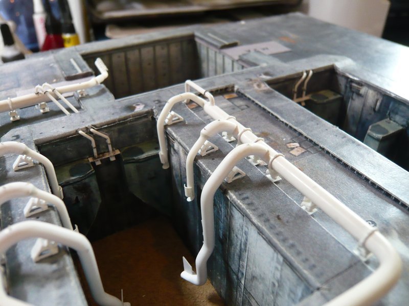
So far so good, now I need to repeat the same procedure only still on the other ring line behind the LH2-TSM. ![]()
![]()
2 Likes
Hello everybody,
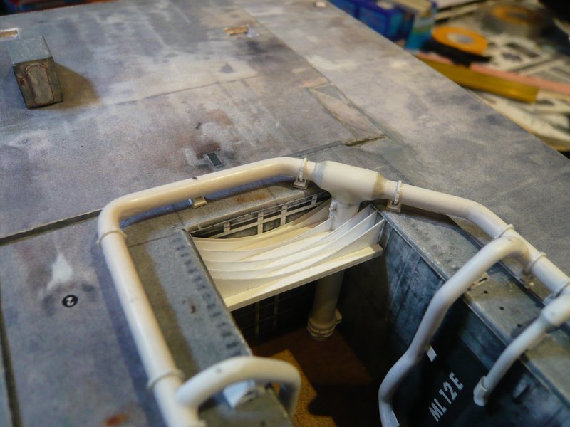
but before I go on with the gluing of the supports on the other ring lines, I want to start (again) with the preparation of the Water Bags, which I had already begun a long time ago, until the reconstruction of the SRB Exhaust holes up to 1:144 has stopped me. ![]()
Since I meanwhile intend to present the MLP both with and without these Water Bags, I first had to think about how best to solve this constructively. ![]()
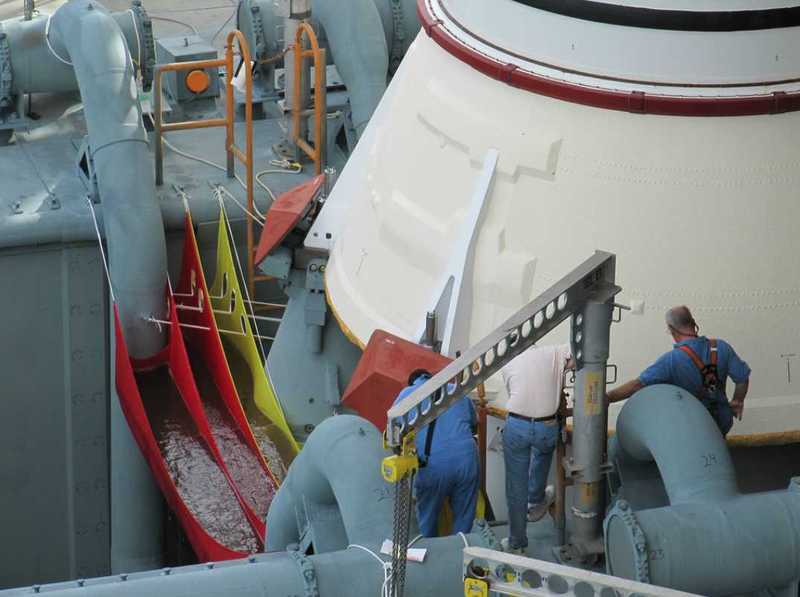
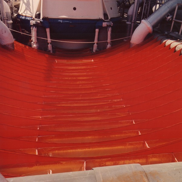
These elongated foil water bags, which are suspended into the SRB shafts, are filled with water only to a height of 12" (approx. 30 cm), as can be seen here again.

With a width of the (most) bags of also 12’’ and a length of 20’ (6,10 m shaft width), the result is about 550 liters of water per bag, which corresponds exactly to the volume of my aquarium. ![]()
First, I want to start with the bags in the back of the chamber (Secondary SRB Hole), with the first part reaching from the shaft back wall to the 18’’ outlets (Ø 46 cm) which contains 18 of these red bags. This will inevitably become a few less for my MLP because of the modification of the SRB holes … So what! ![]()
As can be seen in this image, the first water bag is hanging between the chamber back wall and the 36’’ feed pipe (Ø 91 cm) and is therefore somewhat narrower than the other bags in front of the pipe. The next two bags are somewhat wider than the remaining ones and also shortened in front of the inlet pipe, which should be taken into account in the following design. 
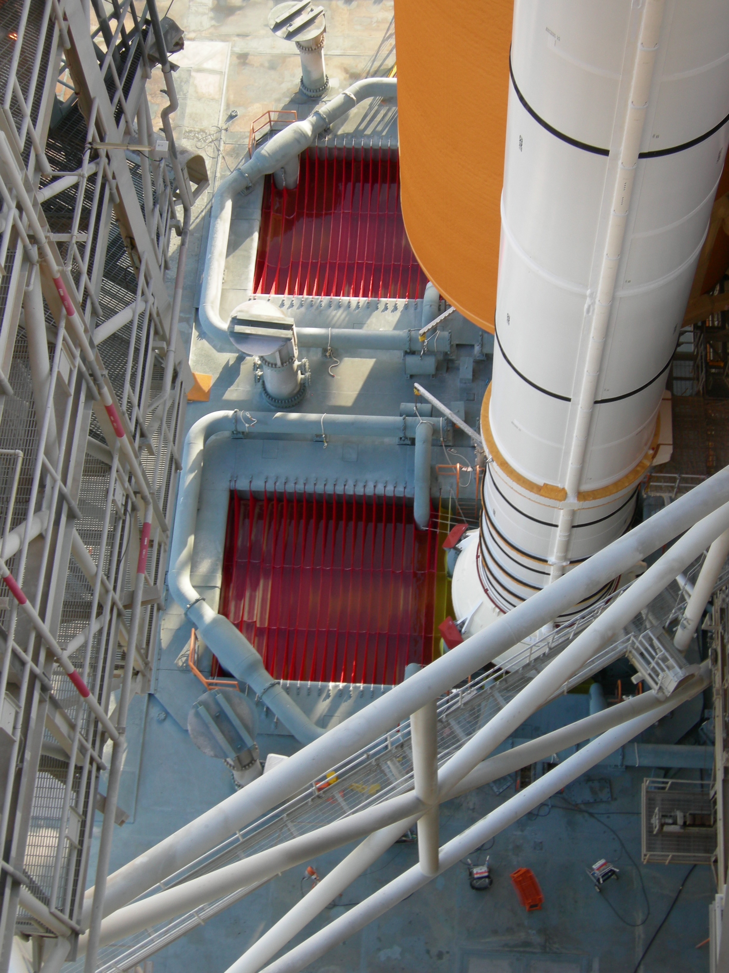
Source: flickr.com (Andrew Sheer)
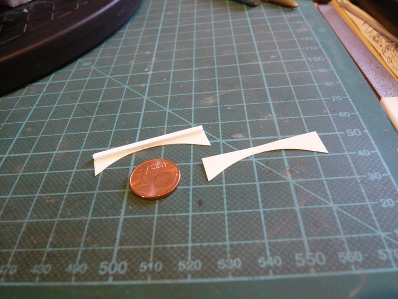
So I first took measurements and made a new template for the partition walls,
and therefore get to work! 
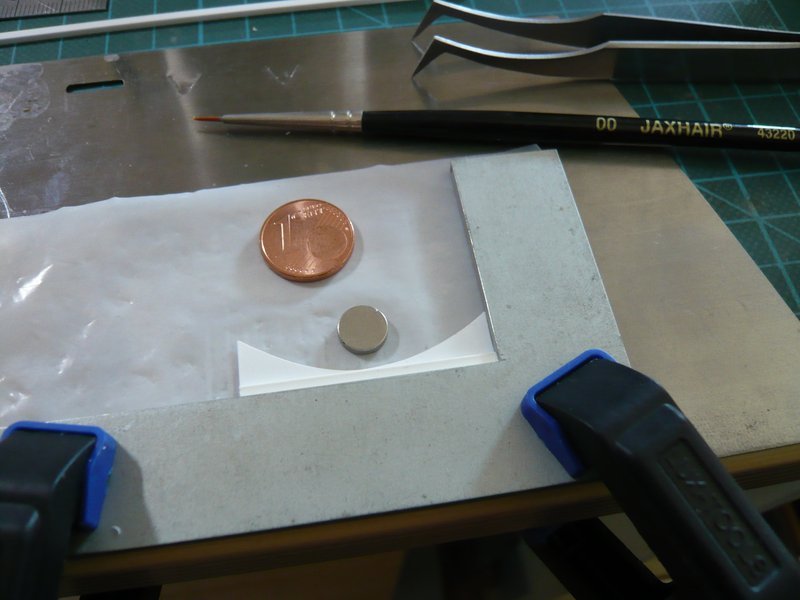
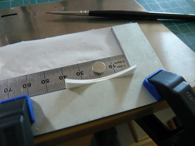
Since the distance between the back wall and the inlet pipe is rather small, the first bag can be only 1,5 mm wide.
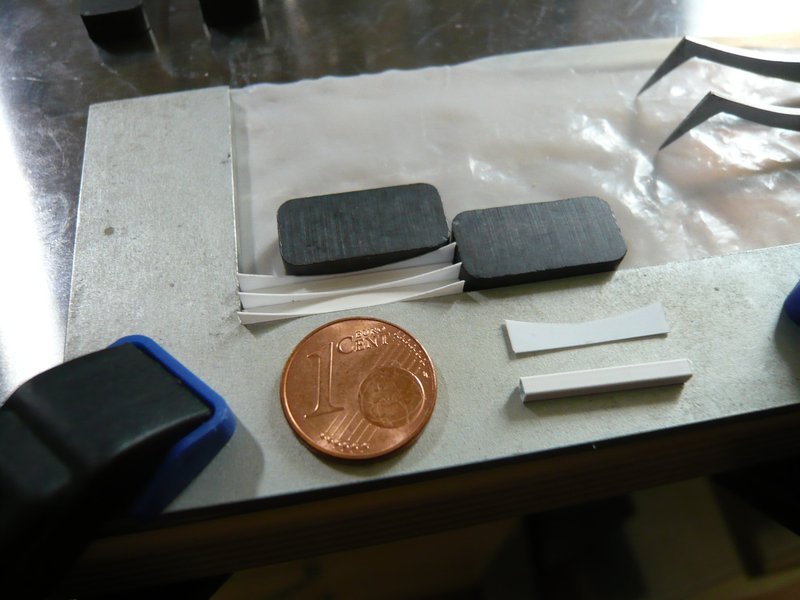
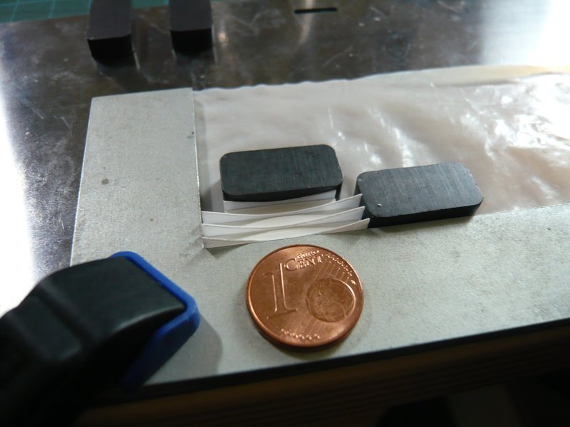
For gluing of the parts with MEK, I have carefully placed Teflon foil underneath. ![]()
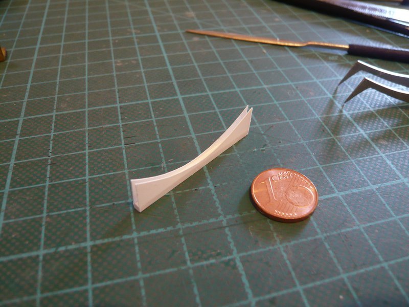
Since the bag has a bit jammed during insertion, the length had to be adjusted slightly. 
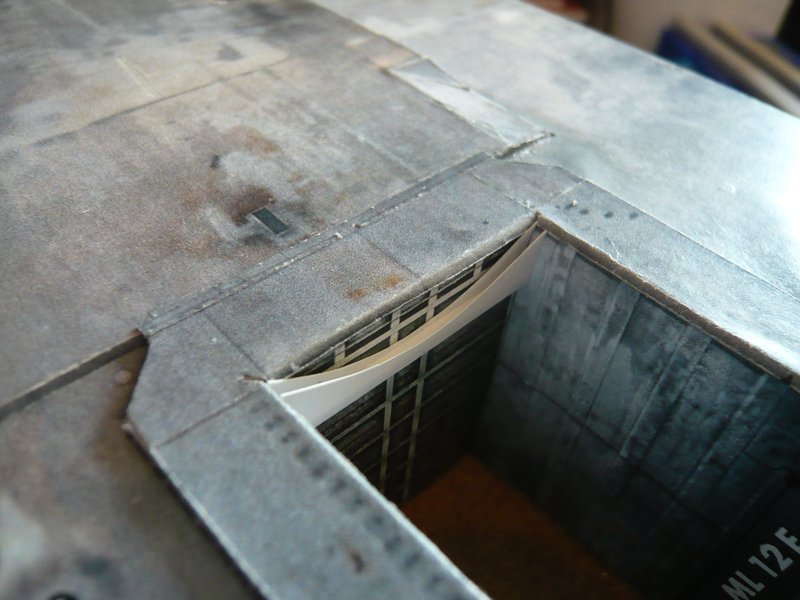
Therefore the question for insertion came up, so it is probably more favorable to insert the bags later from the bottom into the shaft with installed ring line, because the SRB Blast Shield slightly protrudes at the top edge and therefore would disturb. 
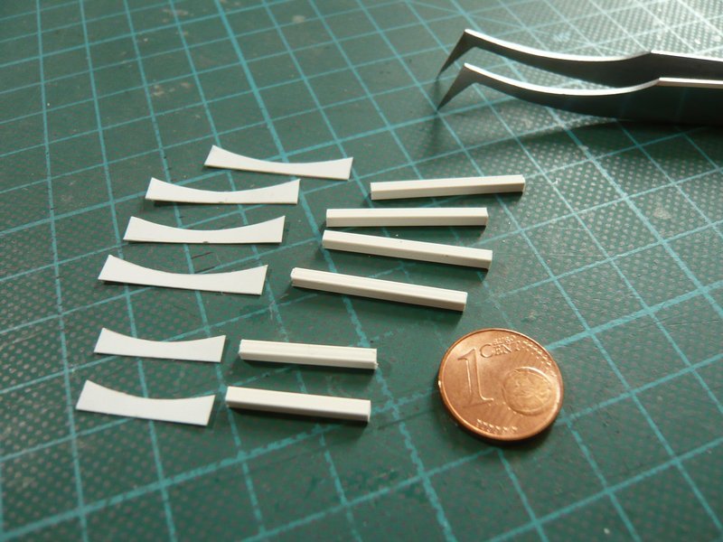
And now to the batch production of the individual parts. For the “normal” bags I will use a square profile (2 mm x 2 mm) for the lower webs, and for the partition walls 0,2 mm Styrene Sheet by Evergreen.
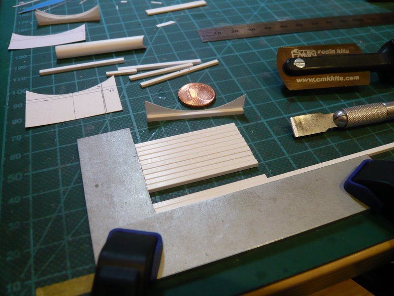
The next time, however, it will go on with the two wider bags next to the inlet pipe (Ø 6,2 mm), for which I will use a rectangular profile (3 mm x 2 mm), after which the normal bags will then follow.
![]()
3 Likes
Hello friends,
here is the next step on the way to the Water Bags, which are going to be composed of several parts, but always beautifully in sequence, just like during the later assembly. ![]()
The first part is the slightly narrower bag (1,5 mm web width) behind the inlet pipe, which is already finished and could already be seen in the last post.

The next part extends up to the two 18’’ outlets to which these individual parts belong,
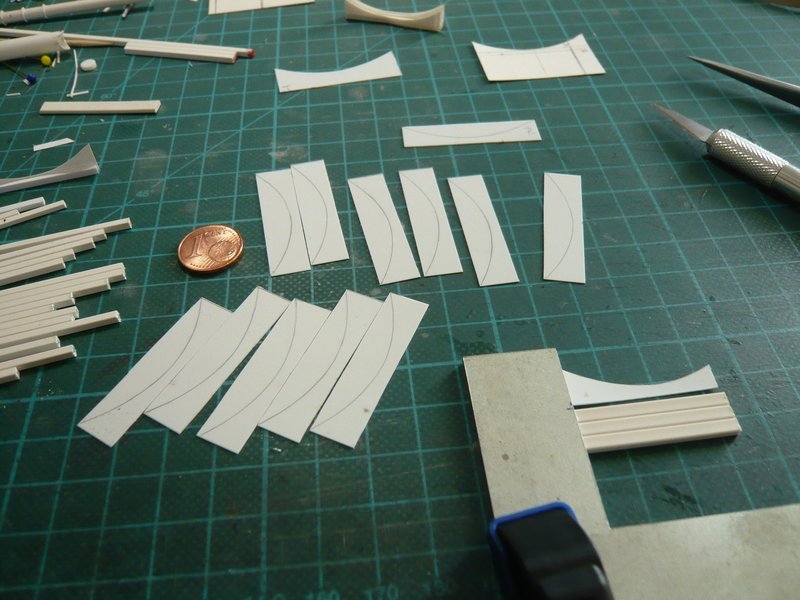
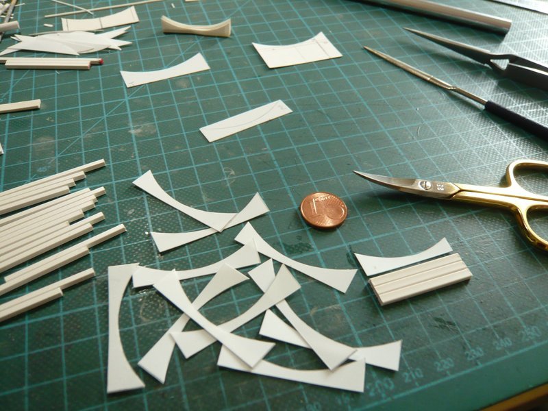
which must be carefully cut out so that the bag package becomes uniform. ![]() Below the scissors lie the wider webs (3 mm x 2 mm) and the shortened partition wall for the two bags next to the inlet pipe,
Below the scissors lie the wider webs (3 mm x 2 mm) and the shortened partition wall for the two bags next to the inlet pipe,
which were next glued.
Then the longer partitions with the “normal” webs (2 mm x 2 mm) follow.
And so the first assembly test looks, which shows that the bags fit quite well and it can equally go on up to the 18’’ outlets. ![]()
Then the third part follows, starting with the bag between the two outlets and the following two “normal” bags, followed by the two short bags between the two rear MLP Support Posts, which unfortunately are covered by the guy in the bluey. ![]()
Source: flickr.com (Jen Scheer)
I hope I can insert this connected third part from above, as well as the remaining three short bag parts on the side walls and the front shaft wall.
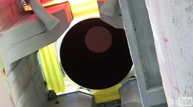
Source: youtube.com (Michel Mephit)
So much for the moment. ![]()
![]()
5 Likes
Pretty cool. This will sure go add a splash of color in all the fine details. I hope you add yellow among the red. I can already see this…Manfred mention Open doors Event and everyone will turn up to see this masterpiece.
Will you be having a hotdog stand outside in the yard? ![]() Kids can play in the park behind the house while the rocket sounds roar the countryside on speakers.
Kids can play in the park behind the house while the rocket sounds roar the countryside on speakers.
![]()
![]()
Hey, do you think we can have the German AF do a flyby over the event? ![]()
OMG Mike, you are a little joker, but fun must be! ![]()
And to err is human, said the hedgehog, and climbed down from the barbed wire. ![]()
Stay tuned for having more fun.
![]()
2 Likes
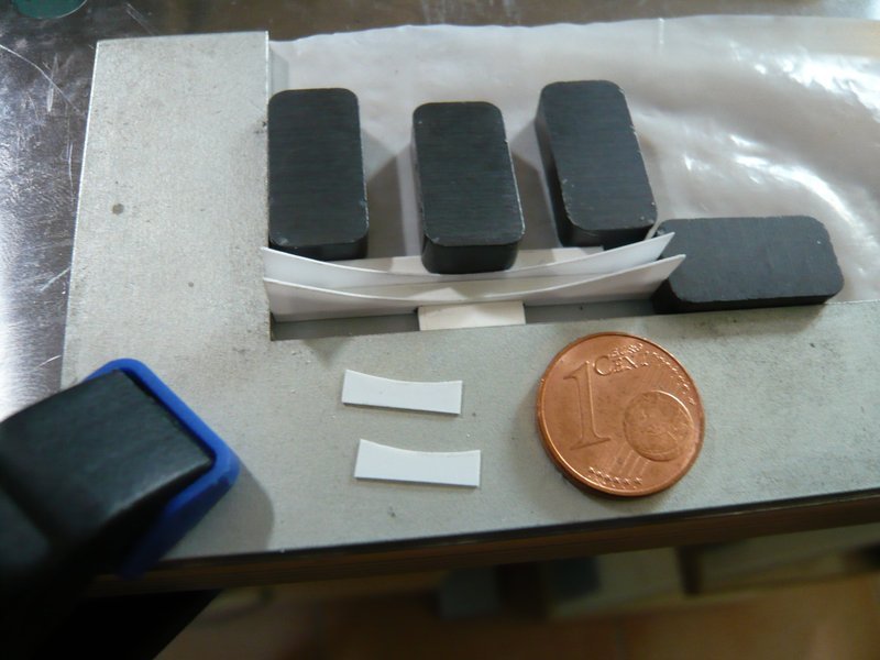
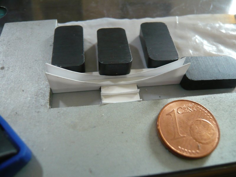
Hello everybody,
here are a few images from the continuation of the gluing of the Water Bags in the SRB shaft behind the LOX-TSM.
And so it went on.
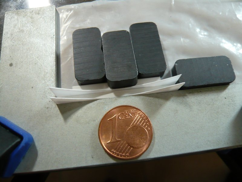
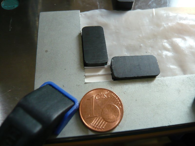
I had to pay attention to the fact that the package could not move upwards, for which I clamped it between magnets and pressed the central webs gently down onto the pad each time and held it tight for a moment.
In this way, I have glued ten bags behind the inlet pipe,
which extend to both 18’’ outlets. ![]()
Then it goes on with the third part, which begins with the wider bag between the outlets. ![]()
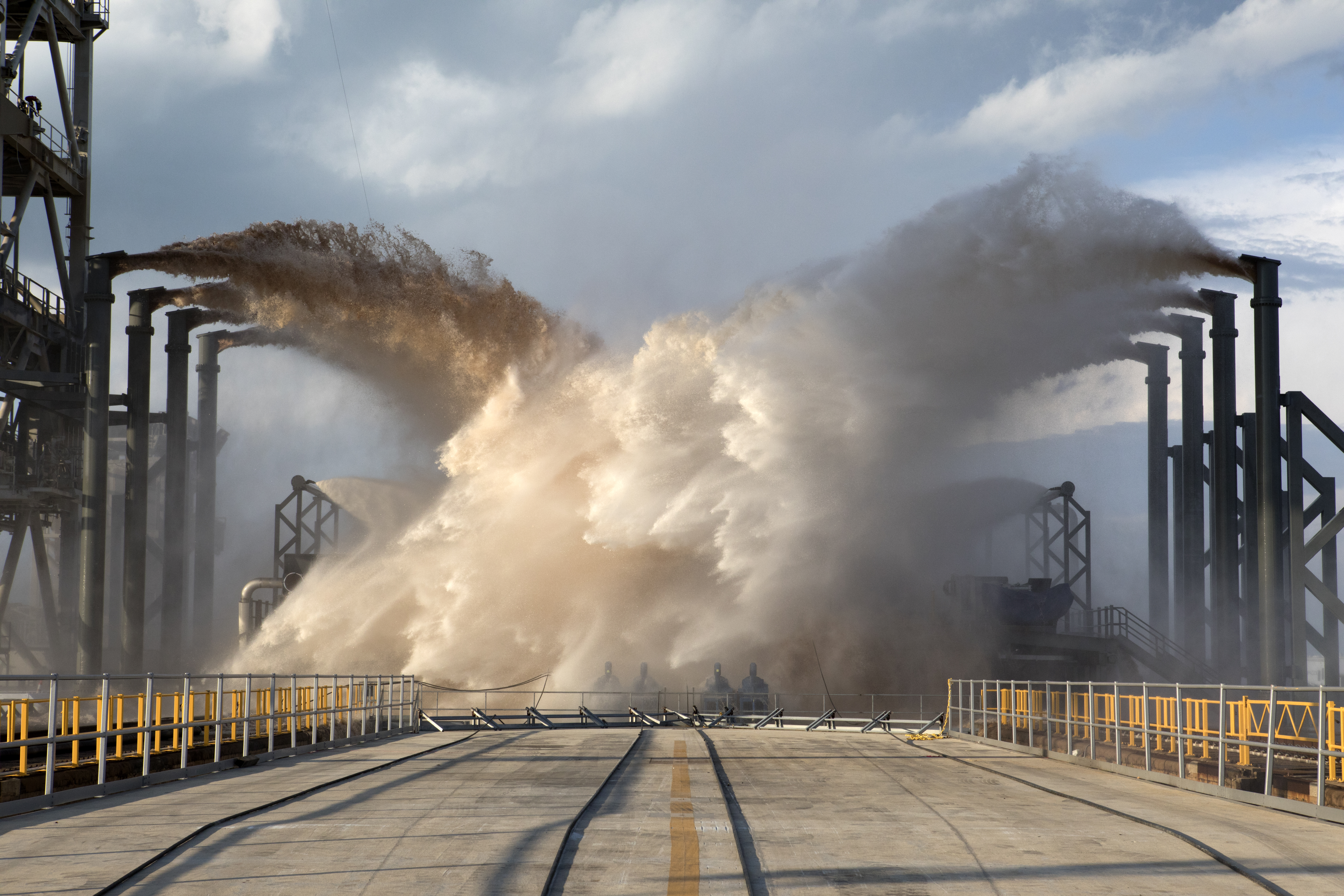
As an encore for all nosy guys I still have this interesting video, in which the ingenious operating principle of the SSWS is very impressively demonstrated and explained. ![]()
Noise Reduction Technology in Space Shuttle’s Lift off Using WATER MIST
Enjoy and have fun.
![]()
4 Likes
The water bags are building up nicely and very uniform ![]() . They will also add a nice splash of colour amidst all the grey tones …
. They will also add a nice splash of colour amidst all the grey tones … ![]()
1 Like
Thanks Mike, I hope so too. ![]()
BTW, have you seen the awesome SSWS Video? ![]()
Stay tuned and let be entertained.
![]()
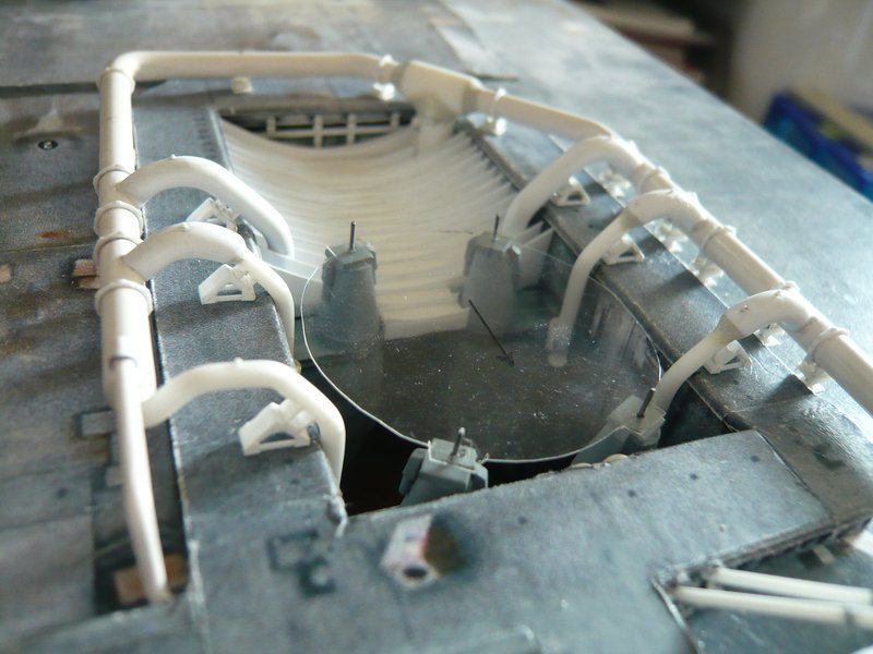
Hello guys,
before I go on with the next Water Bags, I have made a test arrangement with the Shuttle stack on the MLP to look at the space conditions in the front part of the shaft Primary SRB Hole, in which then the shorter bags have to be mounted around the SRB. ![]()
The lineup of the stack was, of course, again a shaky affair, which had to be carried out with the utmost caution in order to avoid fatal crashes. ![]()
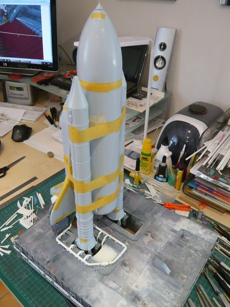
And after this overall impression I put the stack aside and have only placed the support posts upright, in order to get a better view for the further consideration.
And so that the support posts cannot always slip away, I have made a small template of the SRB Aft Skirt. ![]()
And after this detailed view, I then scratched the next two bags, the wider front bag of which is sitting between the two 18’’ outlets.
And these two fit well so far already to the previous bags, wherewith the Secondary SRB Hole would be covered up. ![]()
So far again for today. ![]()
![]()
6 Likes
Nice work and they video is awesome. First time seeing it.
Btw, your shuttle and booster kit is in gray molded plastic instead of white which is in Revell. So, is this Airfix shuttle?
Hi Mike,
yep, this is the Airfix Shuttle Stack (1:144), which, according to experts, should be the best Shuttle Model kit. ![]()
![]()
1 Like
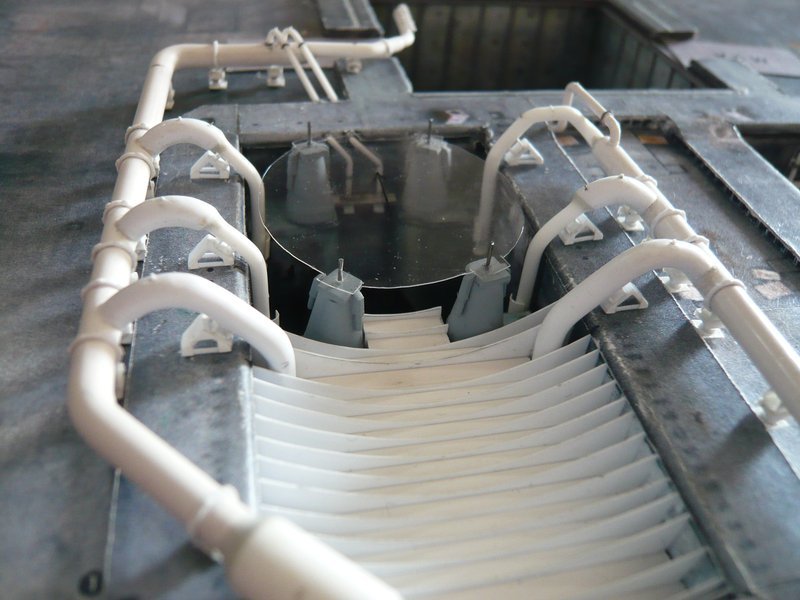
Hello everybody,
and with the clear-sightedness template, the perspective is naturally even better. ![]()
So then let’s go on with the two short middle Water Bags in the front shaft section right in front of the SRB, as can be seen in this image from the STS-2.
And here we go with these two bags in “handbag format”, which are made quickly. ![]()
And they fit well into the gap between the SRB Supports,
and thus also between the MLP Support Posts.
The same two bags sit directly in front of the front shaft wall and have their turn now.
And so slowly the Primary SRB Hole is filling up. ![]()
Tomorrow the two side Water Bags will be added. ![]()
![]()
3 Likes
Hello everybody,
and thus for scratching-building the side Water Bags, for which the parts have been prepared. ![]()
The gluing on the PTFE foil was unproblematic again. ![]()
The outer bag had to be slightly shorter, so that it fits between the two 12’’ outlets.
After the first side bags were glued, I realized that I had cut two sheets too little, ![]() but that was quickly done.
but that was quickly done.
And here both bags are finished,
which could then be tried in the shaft. ![]()
And as one can see, they fit well between the MLP Support Posts.
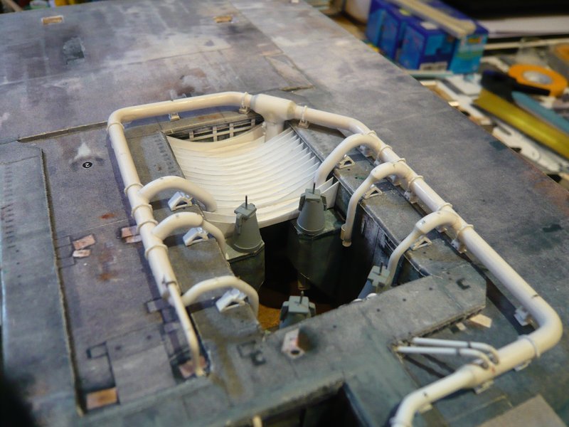
So the left SRB Exhaust chamber is fully equipped now and I can turn next to the right shaft, in order to glue the Pipe Supports under the ring line. ![]()
![]()
3 Likes
Hello folks,
and because it just fits to the SSWS, here out of sequence, a look over to the Pad 39A that time (2017), on which since then one can admire the SSWS of SpaceX, which looks something different.
For me, these photos were new and very interesting, which is why I want to show them here briefly. ![]()
Here is a image of a SpaceX Water Deluge Test with a linked huge HiRes shot, 
Source: flickr.com/NASA (Kim Shiflett)
and here in full action during an early SpaceX launch of a Falcon 9. ![]()

Source: twitter.com/NASASpaceflight (Ben Cooper)
and here a shot from the FSS perspective. ![]()
Source: twitter.com/NASASpaceflight (Ben Cooper)
To these images from Pad 39A one had to become adjusted erst slowly … ![]()
And meanwhile the FSS Tower is clad all around and looks a bit more modern.
![]()
2 Likes
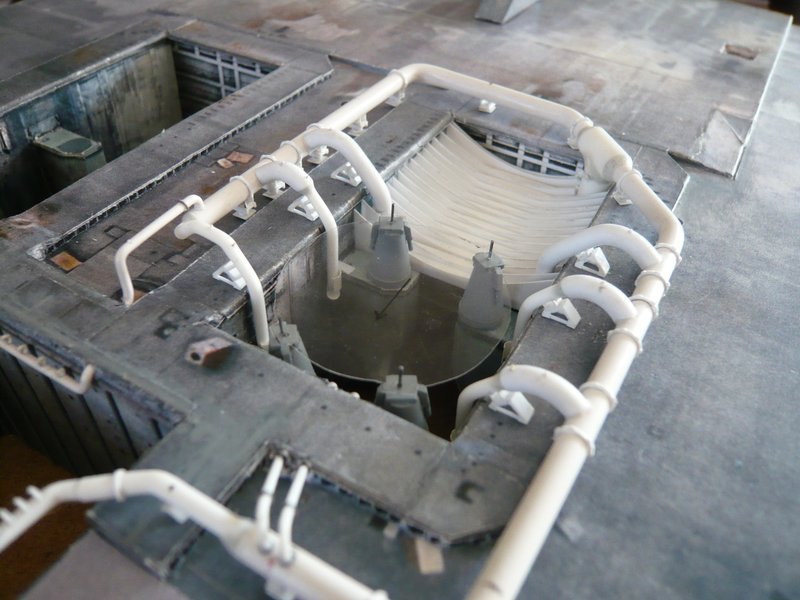
Hello everybody,
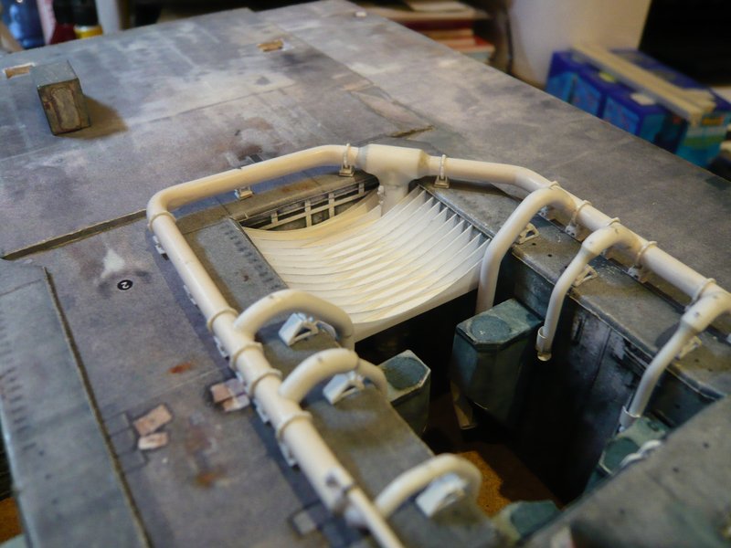
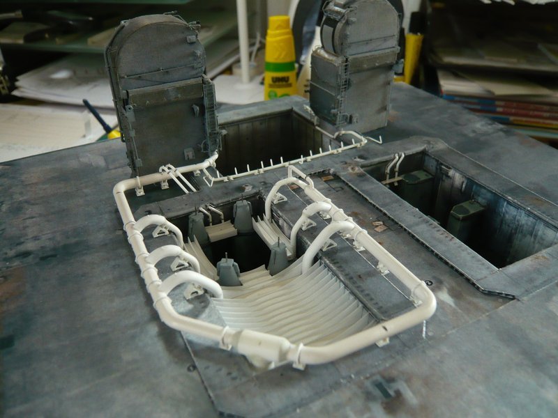
back to 1:160 and to the gluing of the Pipe Supports under the ring line behind the LH2-TSM.
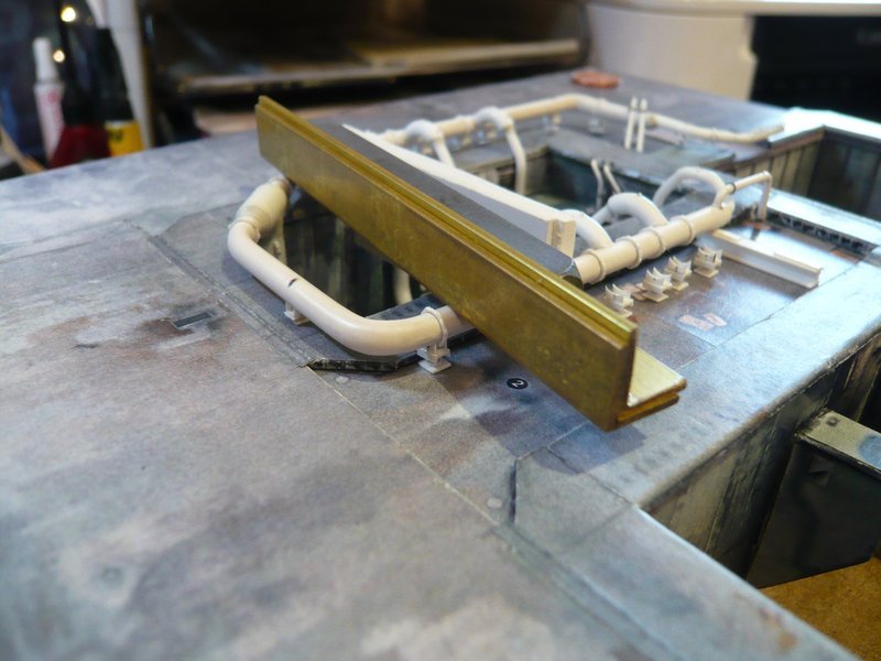
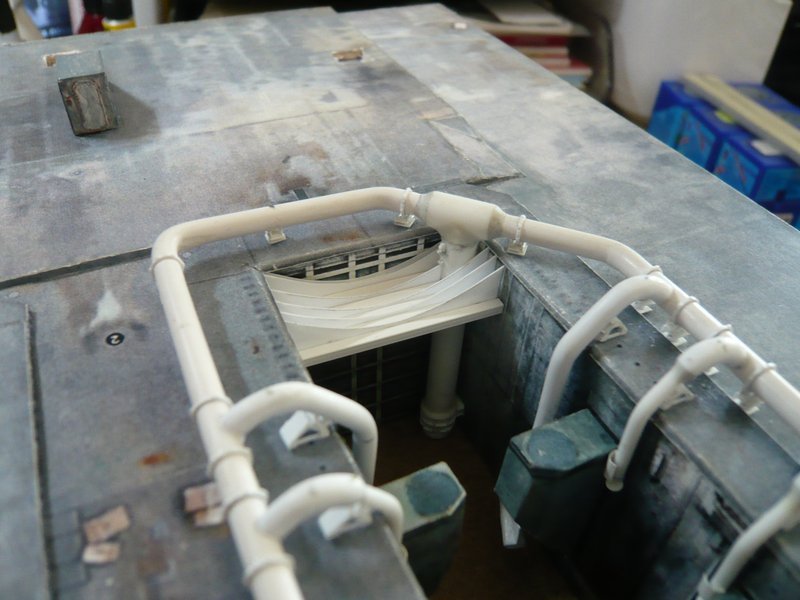
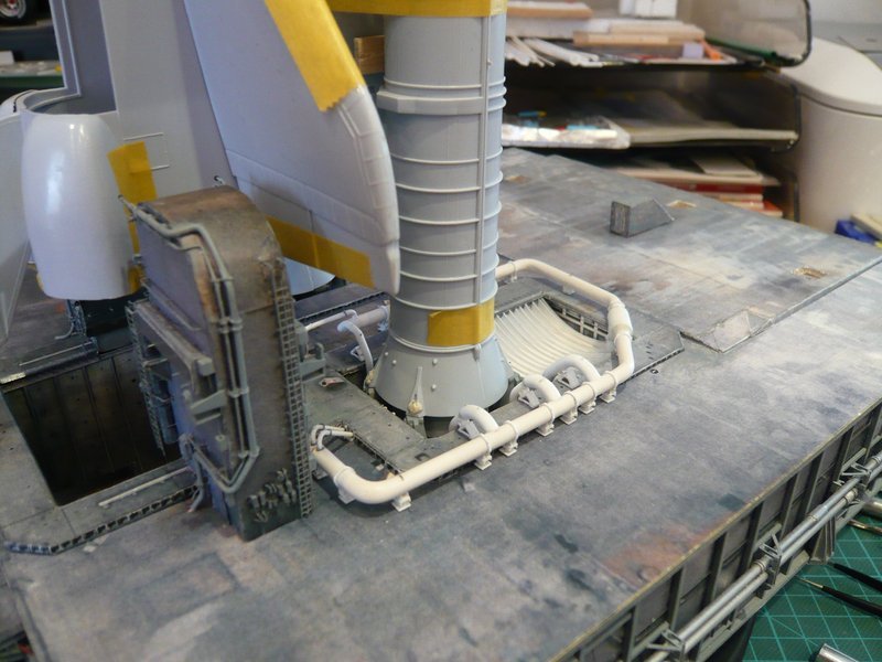
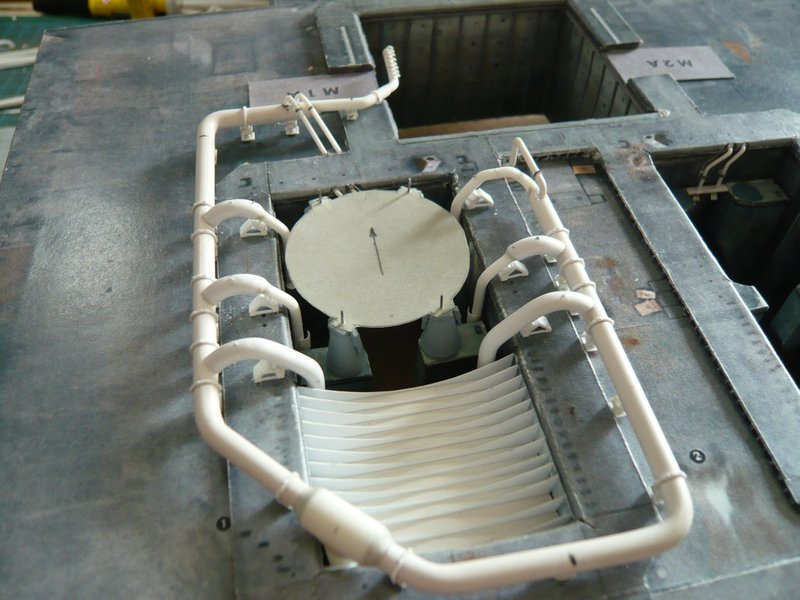
First, I have glued the three supports on the SRB Blast Shield, because this determines the clear height of the ring line over the MLP deck, under which the rest of the supports must find place. ![]()
How re-measurements of the height of the supports have shown, the latter fluctuates by 0,1 - 0,2 mm, which is why I initially placed them only provisionally under the ring line, ![]()
so as to be able to compensate for minor differences by replacing the supports. ![]()
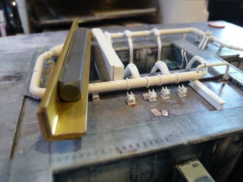
Afterwards, I then glued the front, middle and rear support, so as to get a uniform alignment in the longitudinal direction.

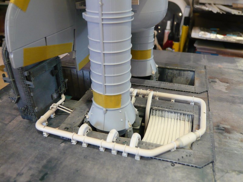
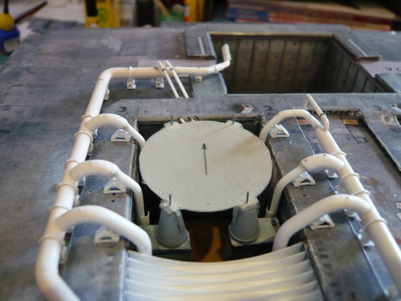
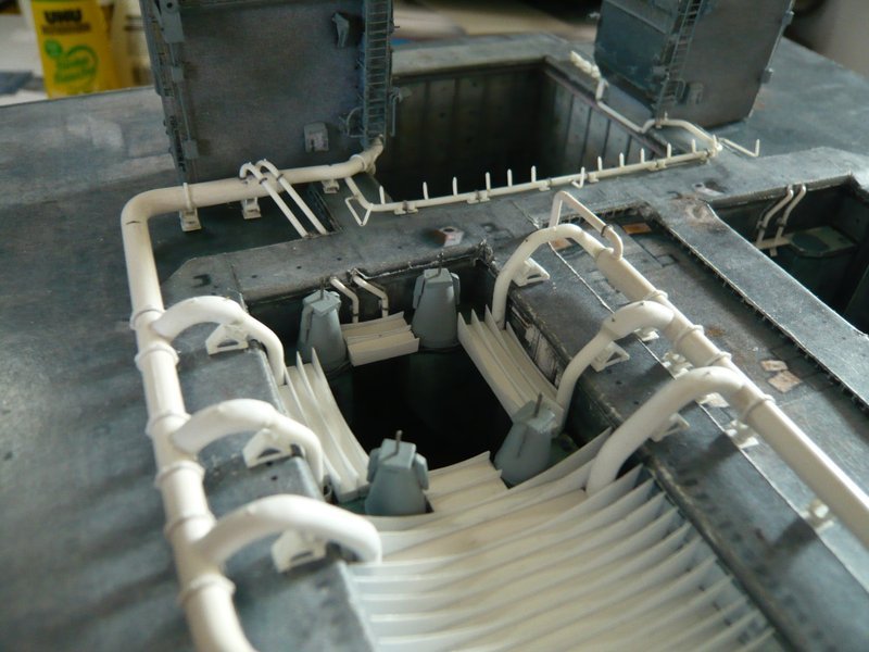
After that, I have removed the ring line again and went back to the bracket holder in the mini vise, which offers more degrees of freedom for the gluing of the supports.
After this strand was completely equipped,
it went on behind the front bow.
For gluing of the six supports on the inside of the line and the six triangular supports under the outlets I then have inserted the ring line again into the shaft.
So far again for today.
![]()
5 Likes