Space Shuttle Launch Complex 39A with Challenger STS-6 (1:144)

Hello everybody,

now there is only one last assembly step to complete the difficult SSWS chapter, I want to do today.

Now there are only 12 supports left, and after the position of the ring line was stabilized, I have begun with the gluing of the first six supports under the ring line,

and so it went on to No. 6.

Next came the six triangular supports under the outlets,

First on the Blast Shield at the inside of the shaft,

and then on the outside.

And after the small support under the 16’’ rejuvenation was glued, the deed is actually done and the tricky SSWS thus finally completed, or is there still something missing?

You are right, of course, since the two slim Supports are still missing under the 9’’ transitions, which I quickly added. And to the celebration of the day the Rainbirds are also coming along in order to finally round out the picture.

And here with a little better light, further panorama perspectives of the SSWS Status Quo.

But this should be enough now, and so I will now look in on the paint shop, whether the guys eventually have time and desire.

3 Likes

Wow, that looks amazing and it’s getting better with every single update.

All that detailed work has made a HUGE impression. I can already see, hours of visual delight for every type of modeler and a Real Space Enthusiast. Bravo my friend!!

2 Likes

This is going beyond amazing…every update just gets better and more intricate… Brilliant work, and the launch photos are pretty cool as well :+1::+1:

1 Like

Thanks Mike and John for your nice compliments.

When I started the SSWS, I never thought that I would be able to scratch these crazy pipe systems, nor that it would be so much effort and take so long.

But all was worth it, and so I’m thrilled with the result myself.

As I said already, the SSWS in its entirety was a hard nut and took lots of effort and was, above all, very time consuming, but so I had always imagined it, wherefore all the effort was really worth it.

The overall view looks really impressive, although one can see many details only from up close and the white plastic also swallows a lot, which will get even clearer in the painted condition.

I look forward every day anew when I see the MLP in front of me, because I know all the details and know where they are.

After this milestone has now been reached, I can sit back for a while and let my tired eyes relaxe a bit …

4 Likes

Scratch-building of the highest quality, seeing how it was achieved makes it even more special. You’ve certainly earned a rest, try not to look at any garden irrigation systems for a while! :clap:

3 Likes

Thanks Tim for your great compliment.

It really was a tough marathon and this fiddling really takes it out of you.

At that time in 2017 I had to relax for 14 days …

Today I have to chuckle, and can easily carry on, after my Brunch.

Hello everybody,

Now I’m strengthened for a while,

and it can go on.

To the warm-up I have first done some small things, which I have put so far aside again and again.

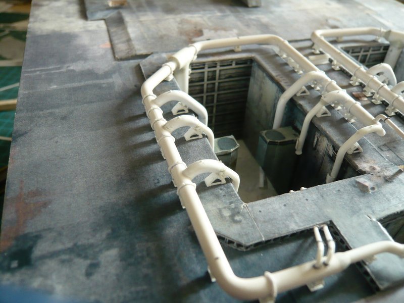
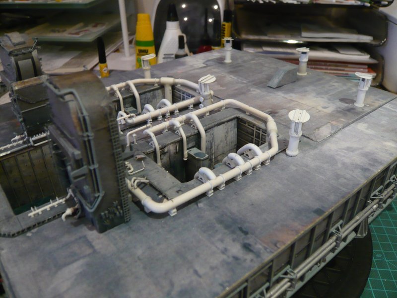
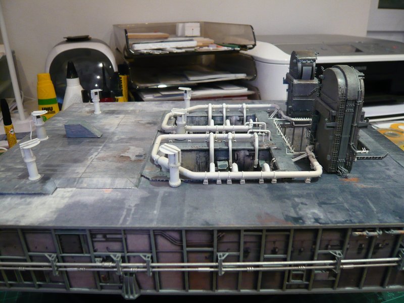
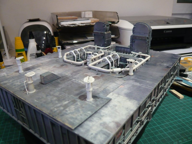
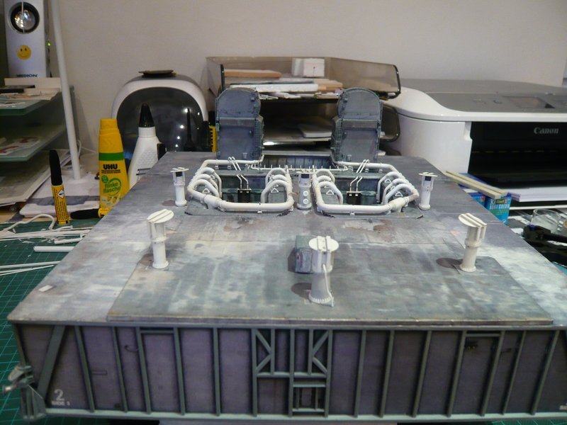
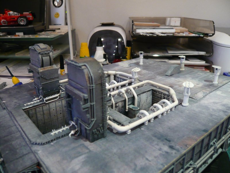
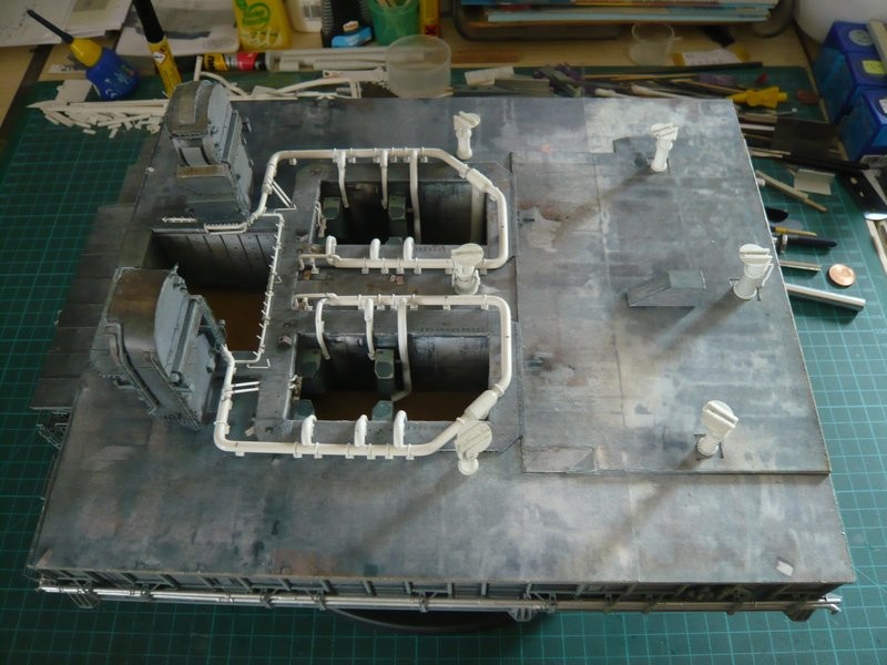
There were initially still to do the openings for the Rainbirds, what were now finally made. Since the openings in the paper kit were somewhat too small, they had to be corrected anyway. In addition, I had deepened them too far already, since they should only be about 0,5 mm deep.

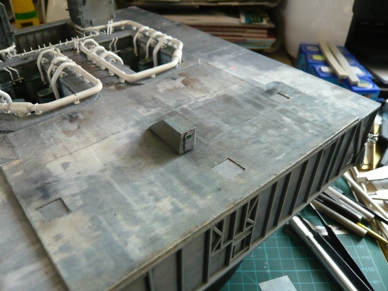
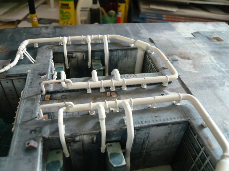
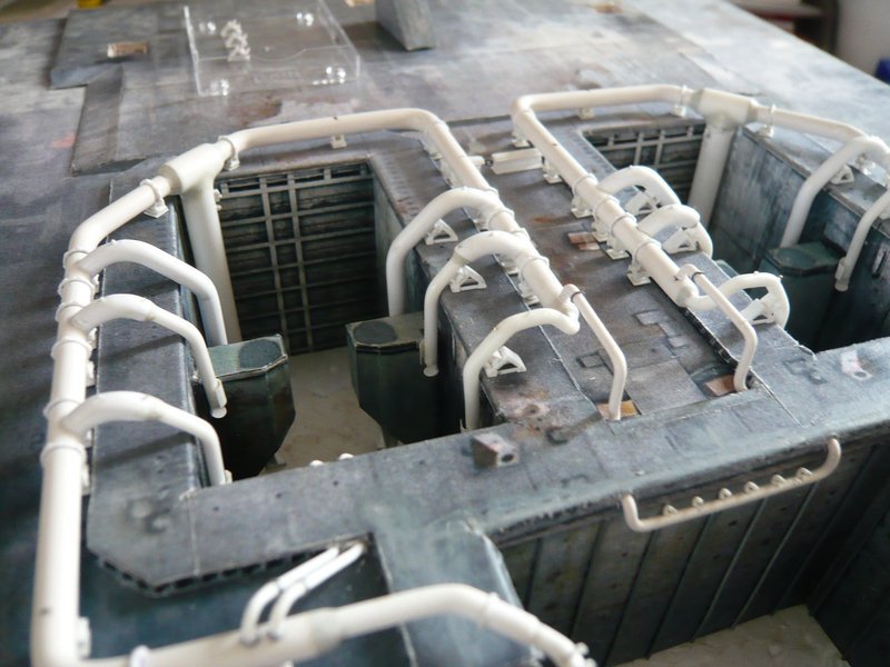
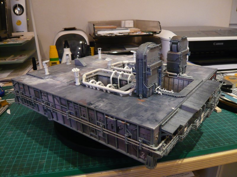
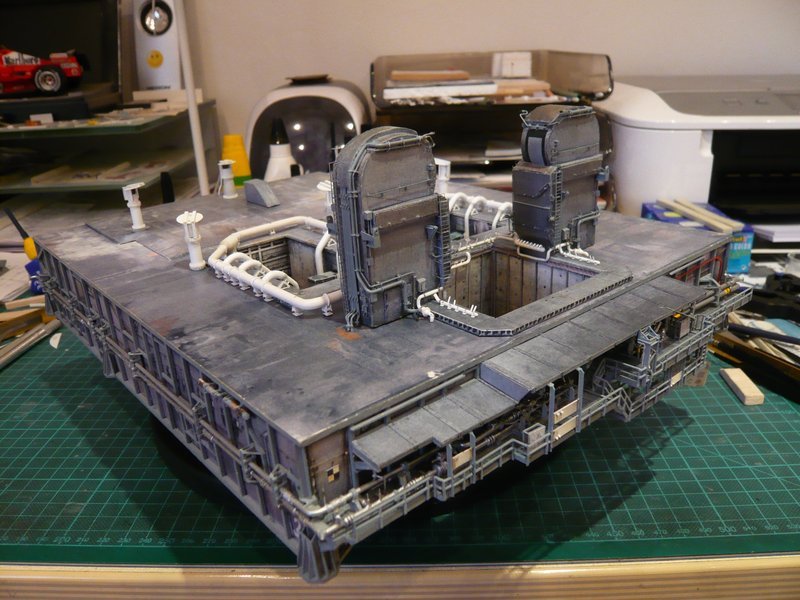
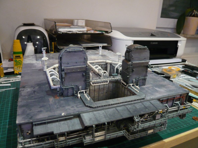
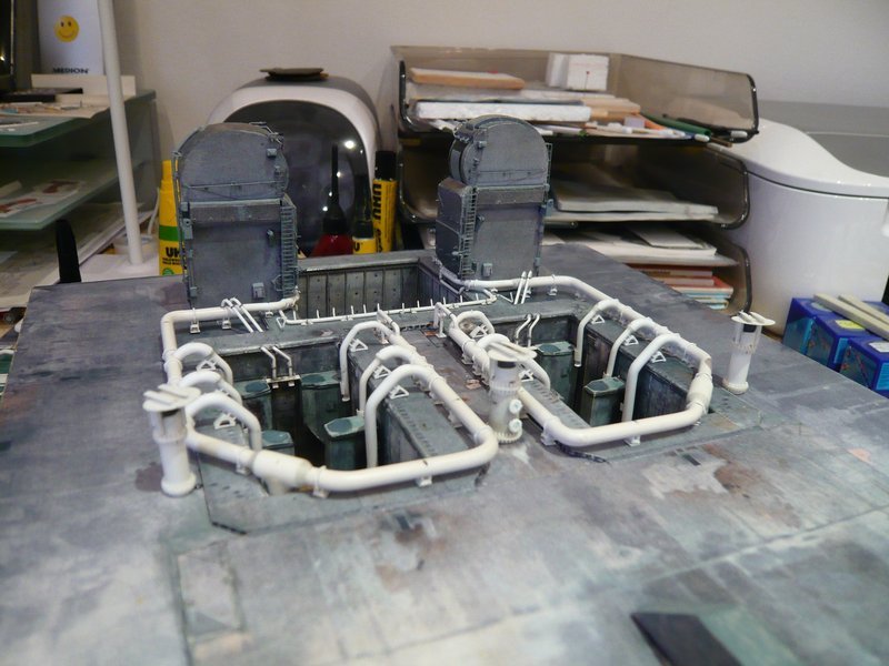
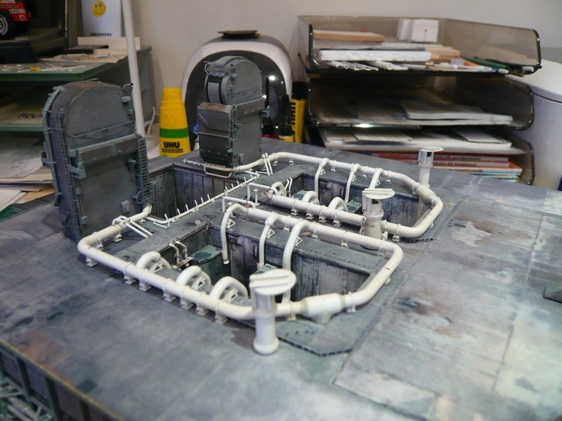
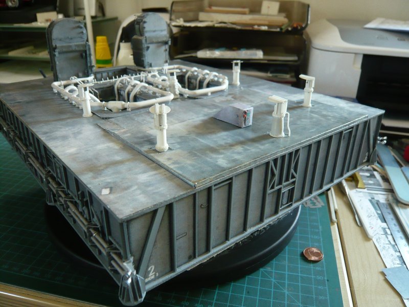
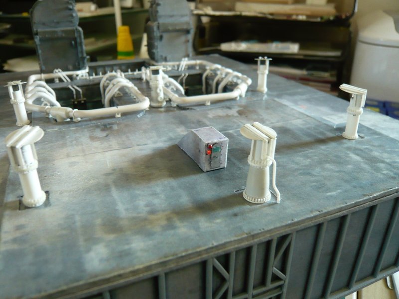
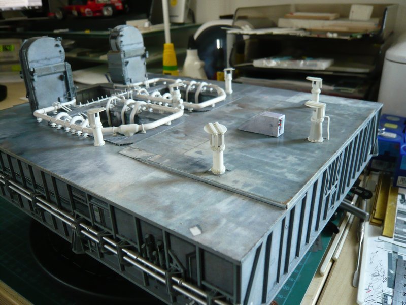
And so the MLP deck looks now from above.

After that, I went to the Stair Housing once more, with which I was not completely satisfied, especially since it was built in an early stage, in which I was still not as exacting and crazy for details as today.

Since the housing from the Paper Kit especially at the back with the door looked relatively pale,

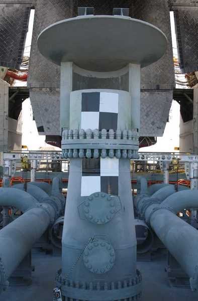
I had it at that time a bit weathered, which then but became a bit too dark. In addition, I had now found some detail photos, which have naturally animated me for scratching.

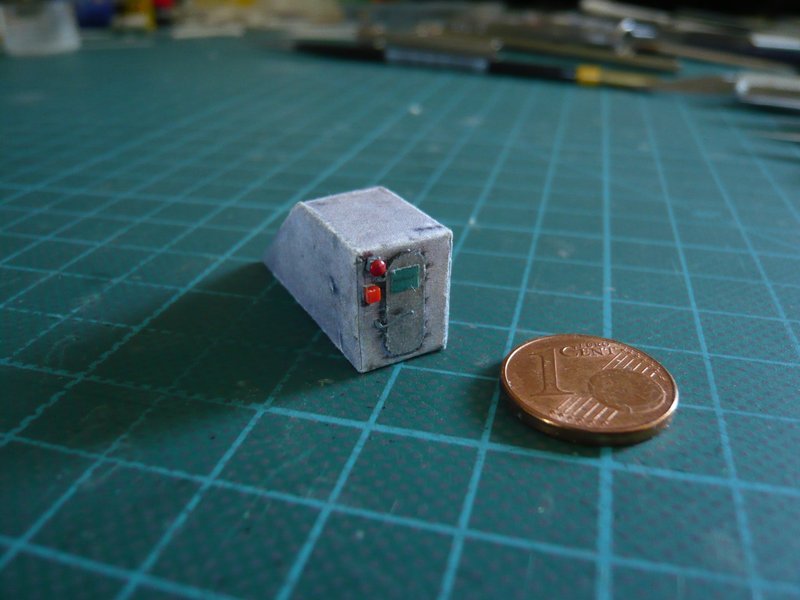
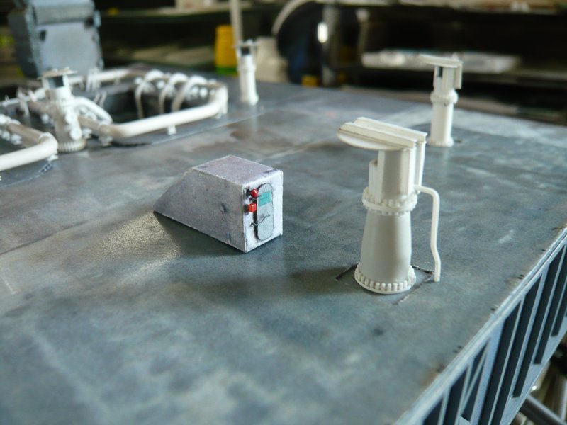
In this image one can see some details that seemed feasible to me, especially this red warning bell in the upper left corner.


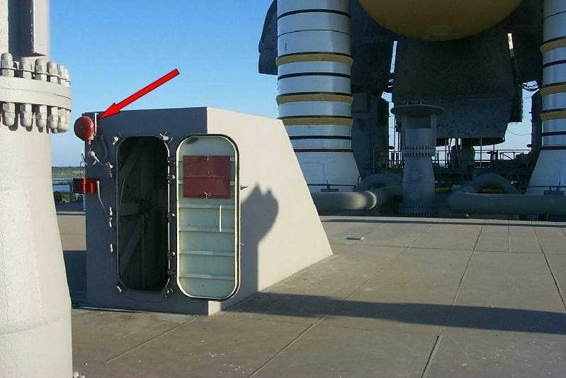
Source: capcomespace.net

Here is a similar image from that time from the other side.


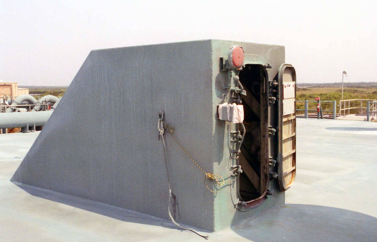
Source: apollosaturn.com (John Duncan)

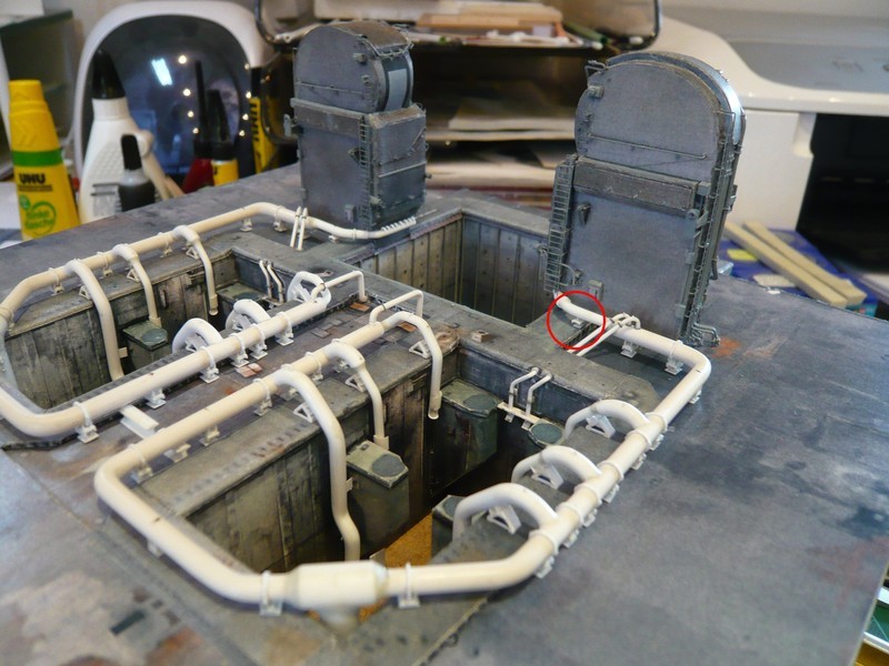
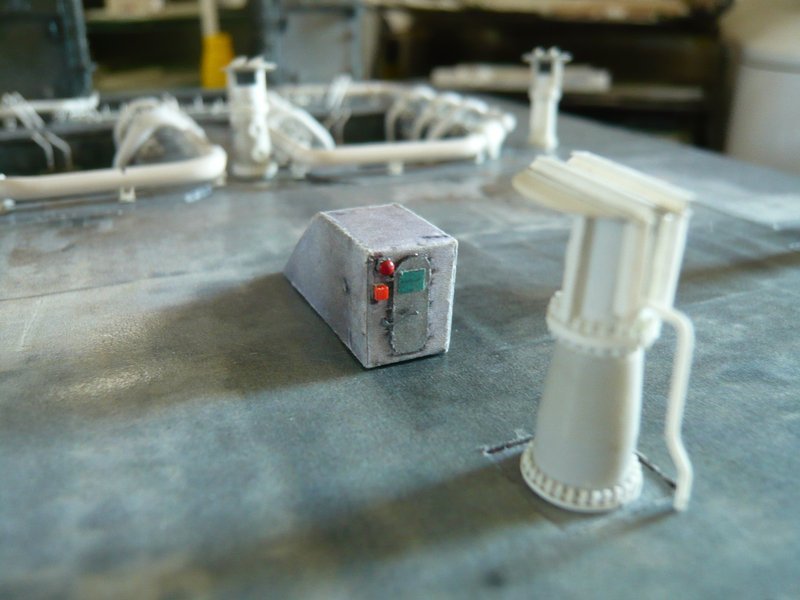
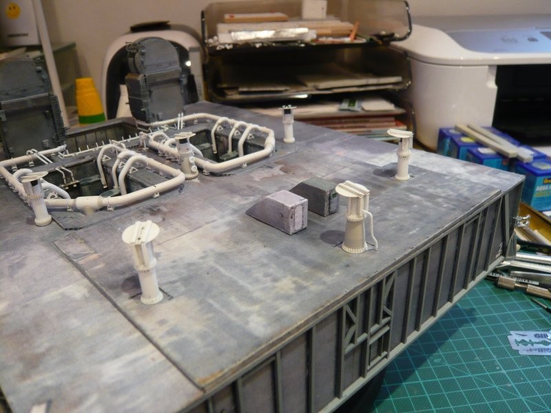
This is why I built the housing once again, and now I find that the coloring, except for the too bright door, it fits better into the picture than the old one, which in turn is pure taste.

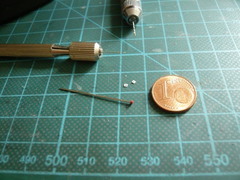
And now to the required small parts, e.g. this bell. At first, I had thought of small red discs, which I had punched out of the cap of a thumbtack, which should be about 1,4 mm in diameter.

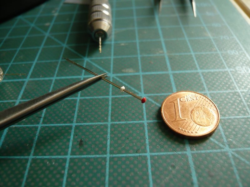
Then, of course, there are also pin needles with correspondingly small, flat head, which I dipped briefly in red color, which looks almost even better.

For the red box underneath the bell, I used the holder of an interdental brush, from which I have cut off one of these side pins, which correspond to the required size with 1 mm x 1 mm.

As one can see in the images, the bell sits on a small support or socket, which I still need to color.

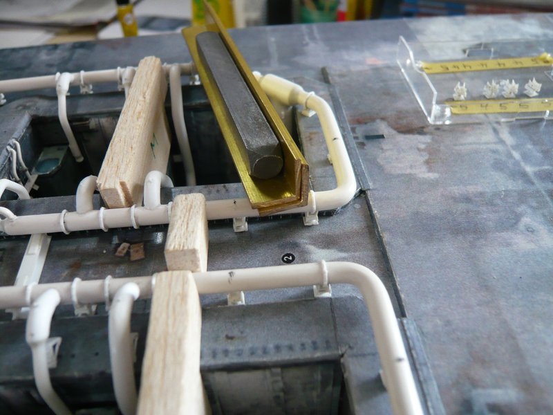
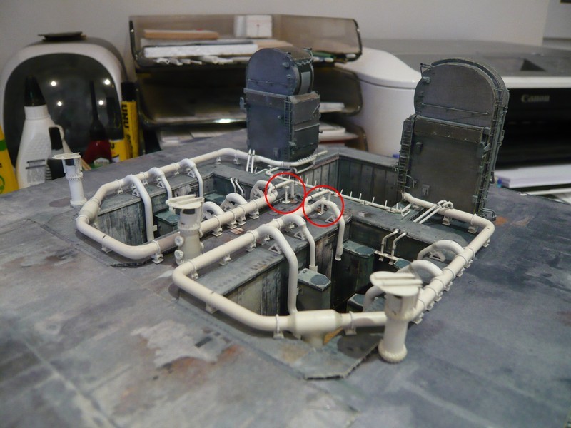
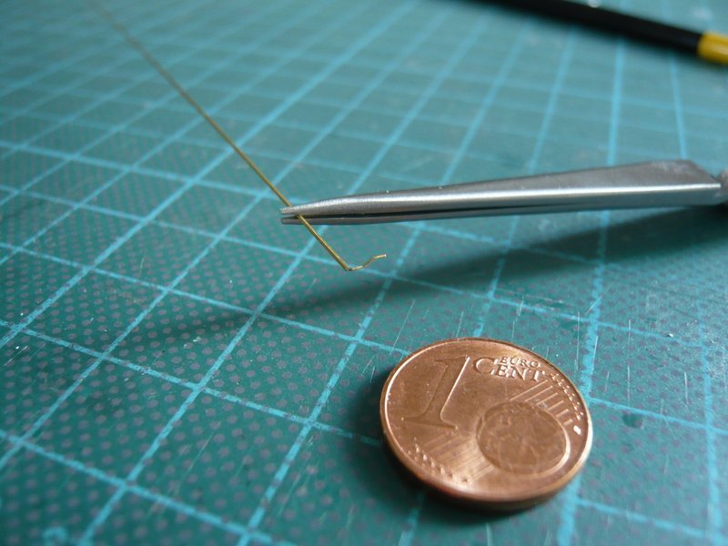
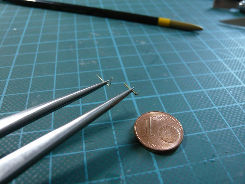
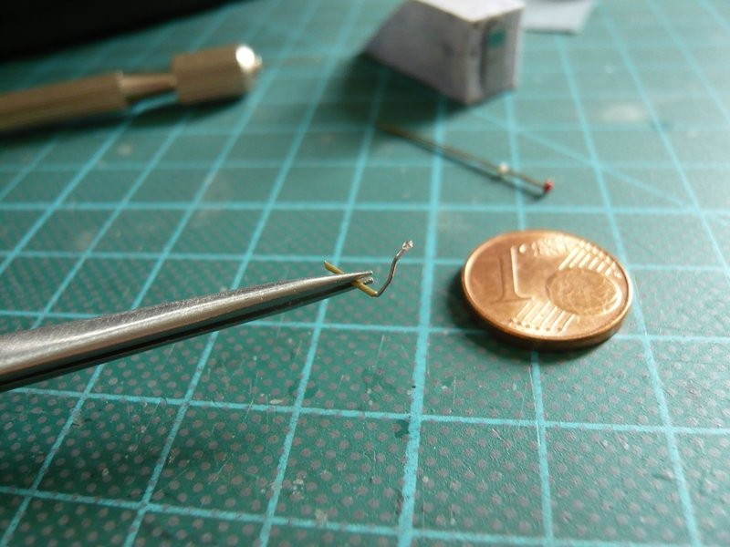
Then I tried the lower longer locking lever made of 0,3 mm steel wire, which is inserted in a brass pipe (0,4 mm) and could be rotated thereby. The ball handle is a glue drop, but it is still a bit too big.

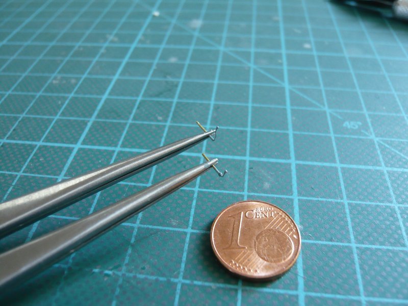
Since the lever seems to be too long and too thick on the housing, I have tried the whole thing again a little smaller and shorter, with brass wire 0,2 mm in a 0,3 mm brass tube, but still without a ball handle.

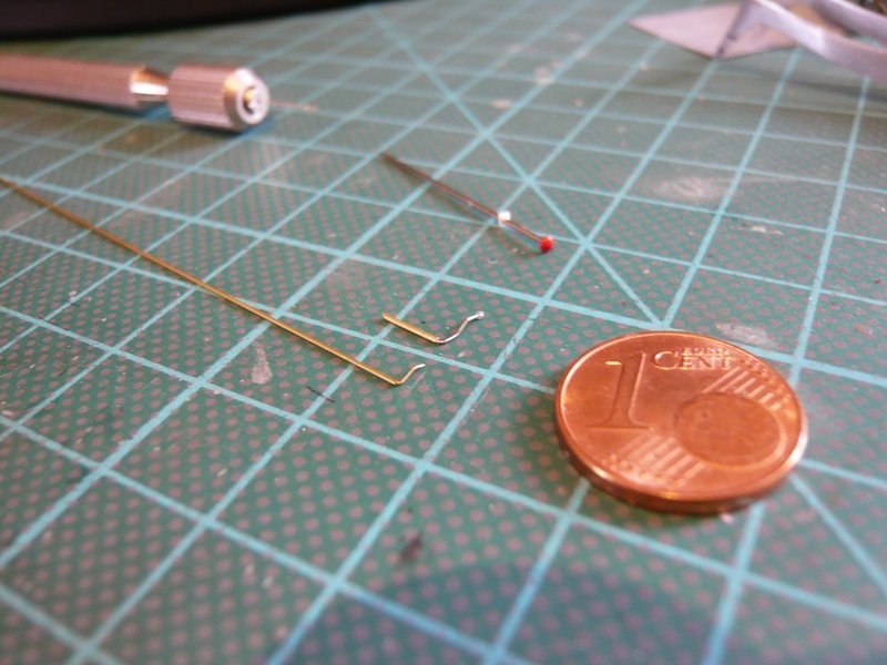
This could already look better and should be tried on later.

4 Likes

Hello everybody,

and so on with the equipment of the Stair Housing with some accessories, which has meanwhile also got a new door with a foldable warning sign from red to green and a moderner warning beacon, which one can see after the last Shuttle mission, when the door was closed forever … :weep:


Source: nasatech.net

The two locking levers I have bent once more using 0,2 mm brass wire, which are in a brass tube (Ø 0,3 mm), here the longer lower lever,

and here together with the smaller upper lever, both with a small glue ball.

After both levers were painted gray,

they could also be installed, and the red warning bell and the small box underneath are already attached, wherewith the Stair Housing is finished and looks good so far.

And here are some images with the housing on the MLP top deck.

Again only a small step, but at least a nice-looking detail.
Yeah, and if you want so, one can now hear the bell ringing …
But as long as the warning sign is turned to green, all is good and nothing can happen …

4 Likes

Hello everybody,

now that the rainbirds meanwhile have been seen more often already, I want to show you how long I was fiddling around at them, which are also parts of the SSWS.


Source: NASA

Of which there are well known, six of them, the outer four are slimmer than the two in the middle standing who are somewhat thicker and have a conical midsection.


Source: NASA

Here’s even an interesting comparison, with regard to the size of these monster birds.

The guy in the image is Andrew Scheer, who was very close to the base until the dismantling of Pad 39B, and has taken lots of great photos. And with its 1,85 m, a stately guy, but next to the giant bird rather a dwarf.


Source: flickr.com (Andrew Scheer)

For the dimensions of the two different types of Rainbirds unfortunately I have found different information.

In the NASA Facts (SSWS) one finds that the Rainbirds are 12’ (3,7 m) high. The two middle birds have a diameter of 42’’ (1,07 m), the other four are against with 30’’ (0,76 m) slightly slimmer.

In the MLP Report I found on the other hand, that all Rainbirds only have a height of 10’-6’’ (3,2 m), including the sloping hood that has a diameter of 6’ was (1,83 m).
There you will find for the two middle Rainbirds a diameter of 4’ (1,22 m), while the other four 2’-6’’ (0,76 m) to have what would correspond to the first source.

Well, which source one can believe now?

Therefore NASA drawings would be very helpful for clarifying the question, but I have not yet have found so far.

Because I have scratch built the TSMs in 1:144 in order to fit to the shuttle stack my Rainbirds should also purely optical accord with. That’s why I’ve also looked once again at the Rainbird templates from David Maier’s Paper Kit (1:144).

As one can see, all six Rainbirds of him are uniformly cylindrical, also the two centrally located Birds N2 and N5. While thereafter the Rainbird N5 (behind the Stair housing) has a diameter of 8,4 mm, the remaining five each having a diameter of 7,2 mm.

And to get an idea of the size of the Rainbirds on the MLP, I’ll just build a bird from the Paper kit, then we’ll see.

That’s it for today.

4 Likes

Hello everybody,

a friend of mine from the ARC Forums has sent me this estimation, he made with Solidworks, which is truly a great 3D CAD software.


Source: NASA

That could be right, because the leading edge of the hood is still a little higher. On the other hand, the diameter would be only 0,70 m, while the NASA indicates 0,76 m.

I also have converted the dimensions in this photo based on Andrew’s height but have some doubts.

Too bad that nobody had drawings of the Rainbirds that time.

Okay, I think, that the height in the NASA Facts of 3,7 m will be even more accurate than the 3,2 m in the MLP Report.

The only question is, what height is meant by that, H1, H2 oder H3?


Source: NASA

The absolute height is H1, in which the mounted H-profiles on the sloping hood are included, but is this the height 3,70 m?

The answer my friend …

Since we are now already drifted to the Rainbirds, I have constructed one of the birds from David Maier’s Paper Kit (1:144) to get an idea of the size on the MLP.

And I must say, that’s not easy to have to handle again with scissors and paper.

This is Rainbird N 5, which has this pipe back, which is only indicated in the typical David Maier style.

On the left stands the sleeve (Ø 8,5 mm), right beside is a sleeve of the other birds which have all the same diameter (7,3 mm).

The preparation of the hood was a little tricky, whereat initially irritated me that only four fold lines were declared for the lateral struts.

First I tried to fold this about 1 mm wide strips next to the fold lines, which would then have to be glued together, but what I have soon abandoned.

Therefore, I have separated this ring at the fold lines and then folded the narrow strips and glued together, what looks so in about as it was probably provided by the master.

In the original, however, the struts adjacent to the front opening are angle profiles, the rear two are T-profiles, and up on the roof sit two double-T- or H-profiles, as one can see here well.


Source: nasatech.net

Then came the roof cap, which had to be folded several times to hint the H-profiles,

and was glued up on the top.

Apart of the simplifications, the similarity with the original is unmistakable.

And also the visual impression on the MLP is pretty neat, although the Rainbird appears a bit too thick to me.

Nevertheless, I will but try to get closer to the original by the already indicated Scratch variant, what certainly means more effort, but what the hell?

5 Likes

Hi folks,

the construction of the Rainbirds in themselves certainly should not be a big problem, especially since their tubular structure should not be excessively difficult.

More headaches prepare me, however rather the lot of screws on the flange rings, I want to indicate somehow, the only question is how?


Source: NASA

Since the Paper kit variant but appears to highly abstracted and also to brawny, I have calculated the essential dimensions of the two Rainbird types based on my reference photos, here first for the bigger birds with the conical midsection.


Source: nasatech.net (STS-134)

As reference dimension I have chosen again the diameter (4,0 mm) of 24’’ pipe, approximately beside the rainbird.

After my first estimate I get for this rainbird type to approximately 132 screws, of whom there are two! For the other four slender rainbirds I come respectively to 78 screws, so together makes 576 screws, if I don’t have miscalculated!!!

For the screws dimensions I tend to Ø 0,5 mm and 1 mm in length, for which one could use Evergreen rods. For their assembly but still I have to come up with a suitable solution, since their distance should be about half a screw diameter, what looks like a rather stressful action.

For this action, I’ve been thinking about the following mounting jig, which I will try now. If that works, it should create a kind of cartridge belt like Billy the Kid carried.

For the spacers between the screws rods I use Evergreen strips 0,4x1,5 mm, and in between I glue with MEK in each case strips 0,5x1,0 mm. And in the interstices are then inserted the rods (Ø 0,5 mm) for the screws.

Here firstly is space for the first 9 of up to 36 screws.

To be continued soon, so stay curious guys.

4 Likes

Hi all together,

and here comes the next step. Let’s go to work!

Before I’ll build the whole mounting jig, I first wanted only start with the right side and try with one screw ring, how or whether my idea can ever be realized.

And then there was already a nasty surprise when selecting the Evergreen rods with Ø 0,5 mm for screws, as if Ø 0,5 mm!!!

Since I have a fairly good sense of proportion, I have immediately noticed the scattering of the diameters of the rods in a package, both within a rod and rod-to-rod that has shocked me really.

That goes from Ø 0,41 mm to 0,6 mm, and so one has the agony of choice, and this is in my view quite simply botch!

Well, no matter, for the first test I have used a rod with a diameter of 0,46 mm to 0,52 mm and cut into about 8 mm long pieces, that I’ve inserted into the gaps.

Since the screws have a certain distance from the wall, as one can see here well,


Source: nasatech.net

I have glued to the inside of the flange ring a carrier strip (0,25 mm x1,5 mm) on the screws, in which I have brushed the strip with MEK only at the overhangs.

And that’s already the trimmed strip in which on the circumference of the pipe (Ø 5,5 mm) for the slender Rainbirds only 21 screws have found a place. The number of screws could be further increased if one would use for the spacers in place of the 0,4 mm only 0,25 mm thick strips.

Since this should be the screw ring for one of the slim birds, standing on the Blast deck, there is only one flange ring at the bottom. Therefore, the screws are flush separated and have upwards an overhang of about 1 mm.

These somewhat uneven overhangs can certainly be equalized.

And now came up the thrilling act of gluing this screw strip on the pipe.

Here I’ve first lightly rounded the beginning of the strip and then glued it with CA. And then it went in two or three steps further around the circumference, in which the longer strip has been very helpful, since so I could calmly determine the point of cutting off the rest.

And thereafter the short end was only to glue with CA, and so the first cartridge belt looks like.

And now I am surprised how great it has worked, or not?

Now a Strip 0,25 mm x 0,5 mm is glued even outside above the screws.

But now occurs to me that I wanted to make the carrier strip for this Rainbird type actually just 0,75 mm wide, because the 1,5 mm wide strip I had only intended for the double screw flanges. But that’s no big deal, I will consider this for the other rings.

Anyway, I’m happy that my conception can be realized in principle, as I thought to myself.

6 Likes

That’s a beautiful piece of scratch-building, well done. You reminded me I discovered the same problem with the very fine Evergreen rods a few years ago, I began to wonder whether the thicker ones had been mis-packaged. I guess they’re at the limits of fine extrusion production – or maybe it’s better now, but we both happened to buy old stock.

Thanks Tim for looking in on me again,

with such small distances, all profiles must have the same diameter, otherwise it will not fit and the effort was in vain.

Hello everybody,

but a little gap must already be as on the original, otherwise there would be too many screws too.

Today I glued on an outer cover strip made of 0,1 mm sheet, which indeed at 1,5 mm is too wide for the flange ring, but just to see the effect.

This results in a diameter of 7,3 mm, which would fit well. However, the spaces between the screws are there not filled. Therefore, I have filled them with white wood glue, what looks quite good.

As already announced, I have glued a new mounting jig for the screw rings, and I have used this time with 0,25 mm x 1,5 mm thinner strips as spacers, which has so far designed for 24 screws.

That was again a tedious procedure, but whatever.

Here are both jigs for comparison, at the top the previous with space for 21 screws, and bottom the new 24 screws.

And then I’ve built a second jig as a counterpart for the left side in an analogous manner and been quite astonished when I put both sides next to each other in order to insert the 0,5 mm rods for the bolts.

Look at that, despite same profiles and gaps for each 24 screws it resulted in this length difference, whereby the gaps of course no longer match, hard to believe but true.

I can only explain it so, that I for the left side of the template for pushing together and gluing the strip pairs of spacers (0,25 mm x 1,5 mm) and placeholders (0,5 mm x 1,0 mm) for the rods probably more pressure could have exercised than for the right side. Because by the brushing of thin strips with MEK these are softened, and could thus be closely moved together, which then adds. And the tolerances of strips also possibly are added again.

No matter, in any case, I’ll just use only one of the two jigs to insert the rods and then insert only strips as a spacers between the ends of the rods. That should but actually go, I guess.

5 Likes

Hello everybody,

today I want to give some impressions of a size comparison of the Rainbirds (1/144 vs. 1/160) on the MLP, which has interested me yet.

Since the TSMs (1/144) optically rather dominate the overall picture of the MLP (1/160), initially seemed to me that the relevant details of SSWS (pipes, etc.), and so did the Rainbirds, would better fit if they would also in about 1/144.

But because so far I could not make a final decision, I’ve glued a set of 1/160 (left) and 1/144 Rainbirds (right) from David Maier’s Paper Kit, which I have the lateral angle bars omitted for simplicity.

And here are the first 160’s birds.

And these are the 144’s birds which look a bit bulkier, where it still depends on the perspective.

And here are for direct comparison, the 160’s birds front and the 144er rear.

First of all I have to say, that the diameters of the Maier-Rainbirds are generally too large compared to the NASA facts, which is why they also appear something to sturdy.

The diameters of the smaller 160’s birds are with 6,3 mm and 7,7 mm larger than the NASA-values of 4,8 mm or 6,7 mm, and the 144’s birds are 7,5 mm and 8,6 mm compared to 5,3 mm and 7,4 mm.

The heights H1 of the 166’s birds are 24 mm compared to 23 mm (NASA), and the H1 of the 144’s is 27 mm compared to 25,7 mm (NASA).

So much for the pure numerical values. I think that an average size of the Rainbirds, both with respect in diameter and heights, could be a suitable compromise solution.

And that’s why I have taken for the four leaner birds a diameter of 5,6 mm as a reference base for conversions, which is very close to the NASA value of 5,3 mm.

Conclusion:
From the overall impression the 160’s Rainbirds seem to me a bit too small compared to the TSMs and SSWS pipes, and the 144’s on the other hand but when too thick.

I hope this was not too much numbers now and am curious about your opinion.

7 Likes

I’d agree the 144’s look too big, but the 160’s don’t instantly look too small to my eyes. It may be just an optical trick, but smaller elements emphasise the massive scale of the whole launch pad so they don’t look out of place. However, it sounds like you’ve already decided to make the intermediate size which must be the closest match – I admire your patience once again :+1:

Thanks Tim for your cooperation.

Due to Revell’s scale dilemma, the solution is a compromise anyway. So let’s see how it looks.

Hello friends,

as I said, the 144’s birds are to dumpy for me, but that is also because David Maier was starting from too large diameters, namely 1,07 m (42’') for the slim Birds, although according to NASA, this is the diameter of the two thicker central Birds. And in his kit these are 8,6 mm in diameter, which would correspond to 1,24 m, so in fact, far too “fat”.

Now I have still brought the FSS Tower out of the box, assembled provisionally and placed next to the MLP. These are incidentally the 160’s Rainbirds.

And that the FSS Level 95 and the MLP Deck (Level 0) are at the same height, I have to underlay approx. 1 cm, which would not be problematic.

And from this perspective looks the tower next to the MLP actually quite impressive.

But already in this image one can see where the trip with the shuttle stack goes, namely upwards … And that means that the ET-top actually extends beyond Level 295, what would be not correct.

And in order to illustrate it a little bit, I have placed a brass profile above. And this means about 1,5 cm overhang.

In reality, however, the ET-top lies at an altitude of Level 275, which means that you actually have to insert a complete FSS level. This would, for example, one way of improvisation which would be feasible in principle. But there are possibly some other …
That’s why I have to think about in calm now, then we can continue to juggle …

But this is only one problem of the Revell Launch Tower kit. The other problem areas I have outlined here.

To cut a long story short, the FSS is 7,5 cm too low and corresponds to only 1:168, and the RSS is also 1:168 too.

This results from the fact that all FSS levels are too low. The lowest floor corresponds to only a height of 23.6’ (1:205) instead of 27’, and all other levels correspond to only 18’ (1:160) instead of 20’.

The most glaring optical problem however is the MLP, which is only 1:200. Only the Shuttle stack is 1:144.

Due to the height of the stack, there are problems with the GOX Vent Arm which is sitting too high, namely above Level 275. In reality, however, the upper swivel bearing is on a level with the top of the Level 255, as one can see in this photo.


Source: NASA

These damned scale problems seem to be a never-ending story … But I’ll have to crack the nut and will bite me through.

Giving up is not an option for me!

4 Likes