Hello everybody,
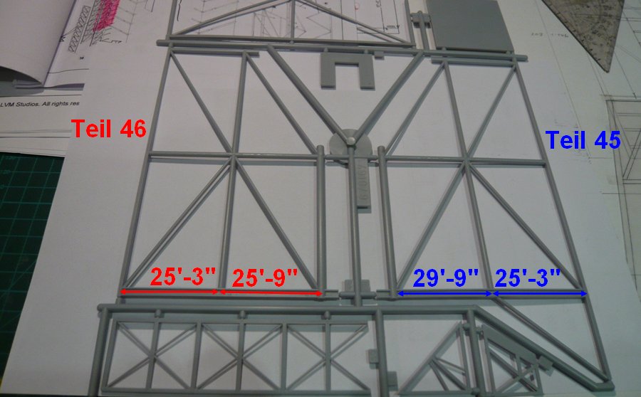
and so it not becomes boring, also on the lateral support structures right and left of the PCR there are similar deviations of the diameter/dimensions of Revell’s profiles from the real structure. 
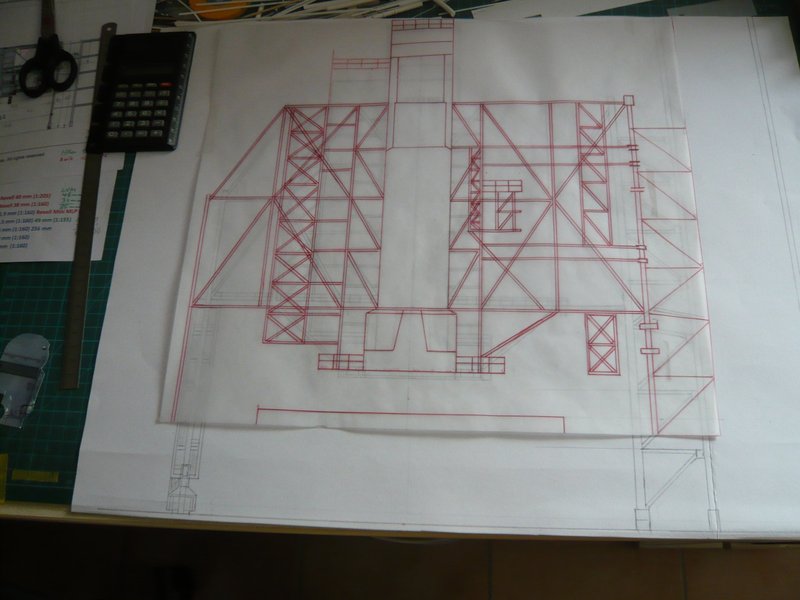
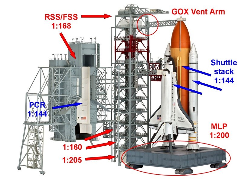
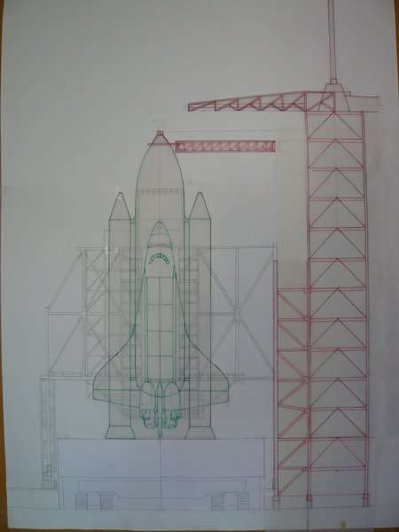
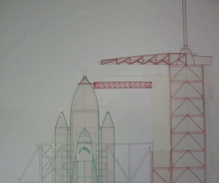
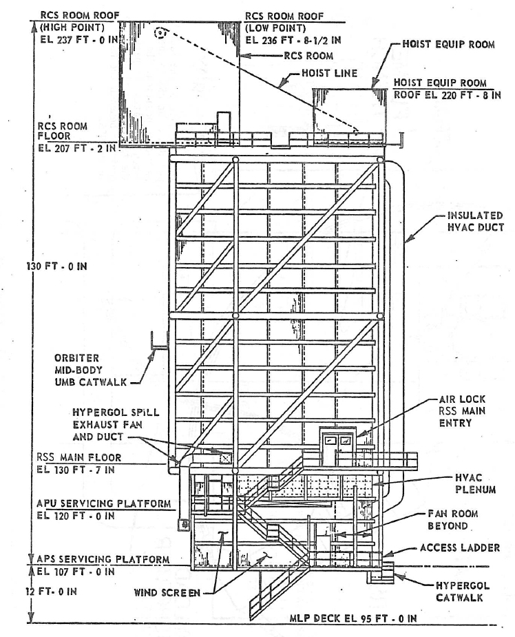
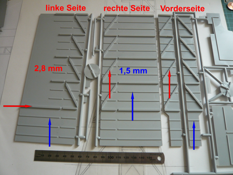
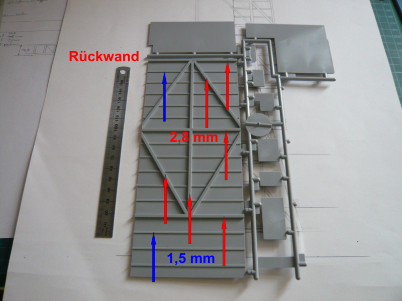
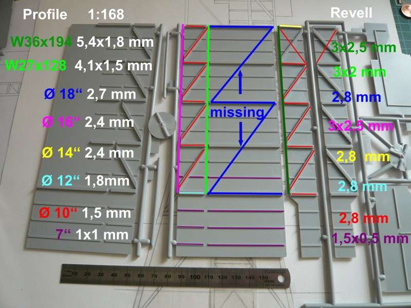
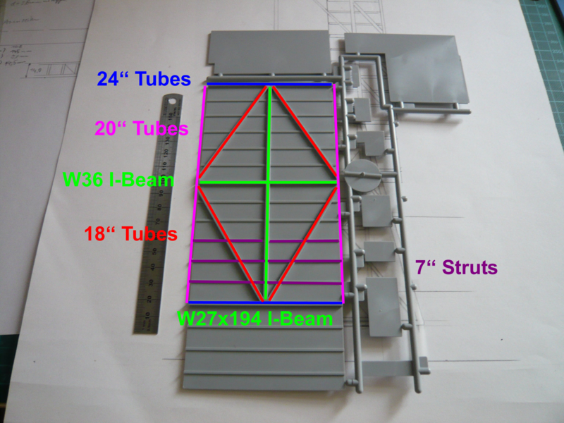
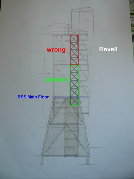
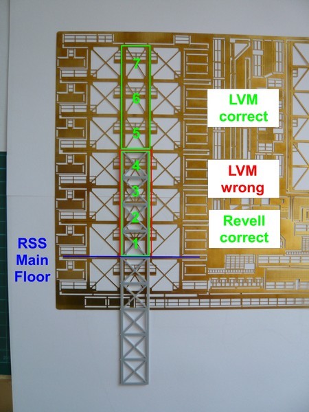
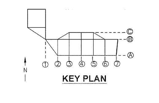
So here’s first the south-facing support structure of the RSS, left the real tube diameters and down-scaled values (1:168), and right Revell’s wrong dimensions. 
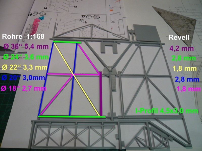
Particularly striking are the too thin central 18’’ and 22’’ struts given the huge RSS structure.  And why Revell has just replaced the lower 24’’ tubes through these I-beams, will also remain a mystery.
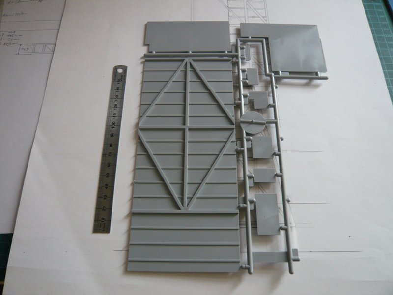
And that probably will not look otherwise on the right side, which I’ll check next time. 
The question remains, how to deal with these thin rods, probably amputate … 
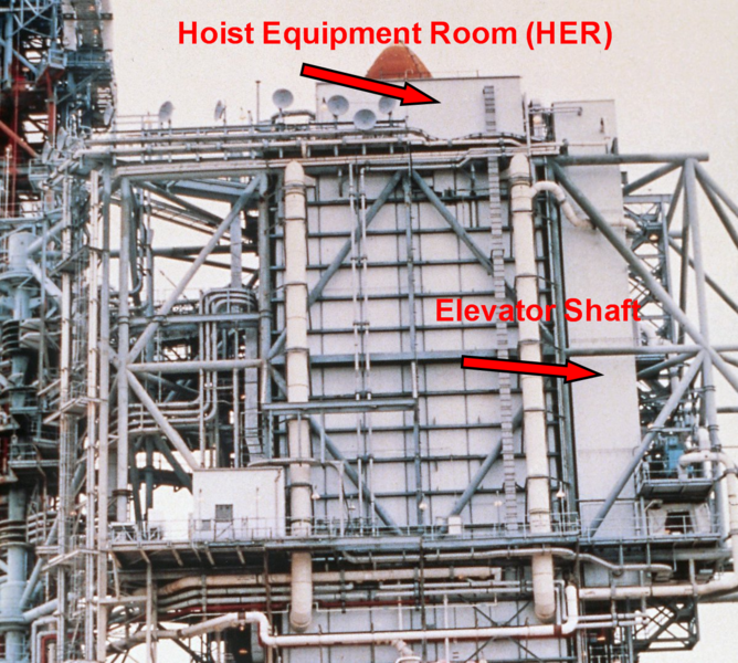
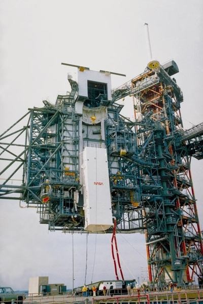
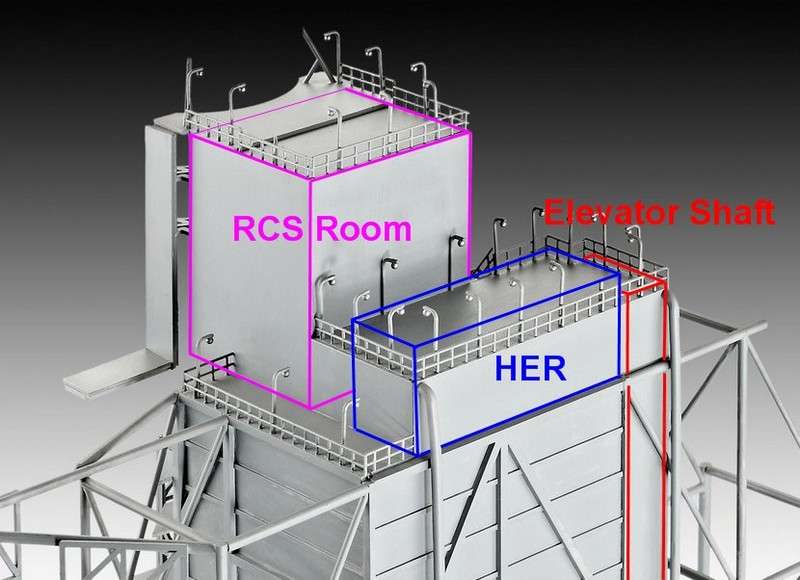
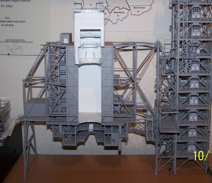
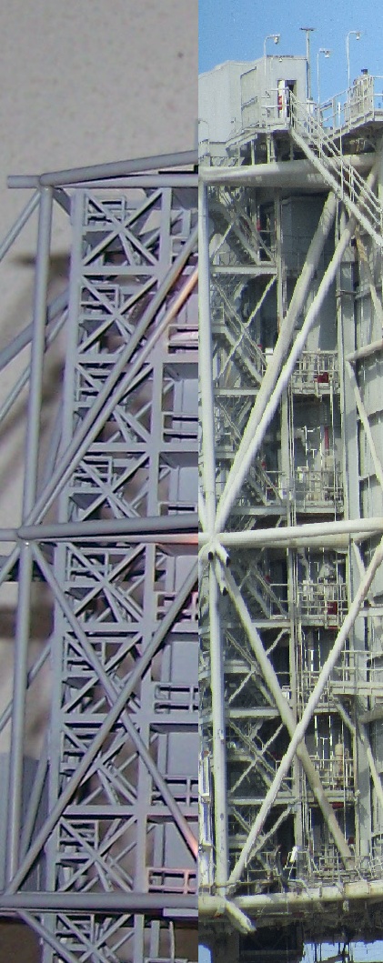
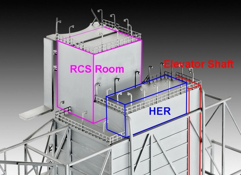
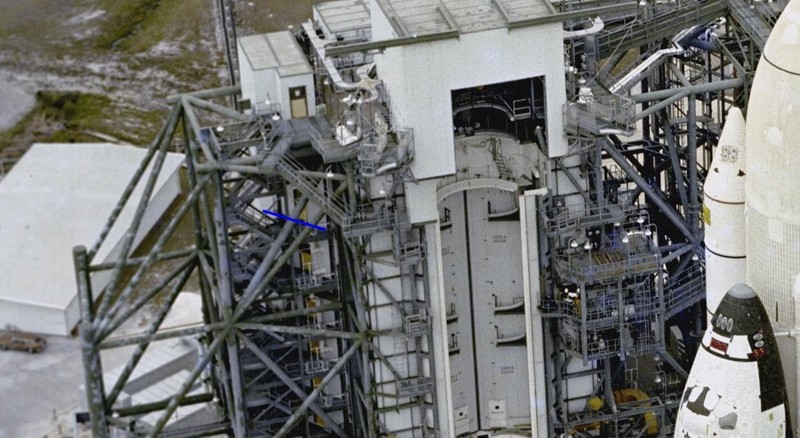
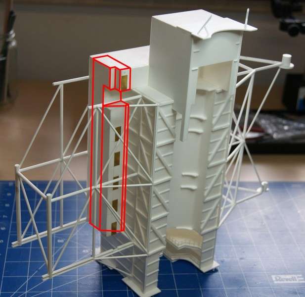
But that is still not enough, during intense viewing of RSS images around the Elevator shaft I noticed that Revell has also strongly simplified the shaft. 
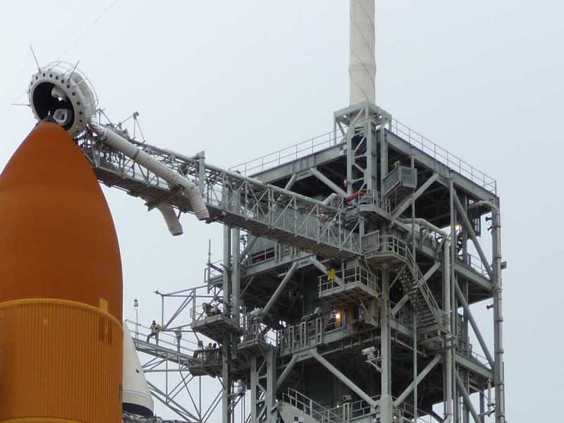
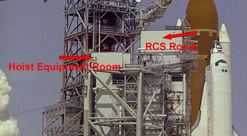
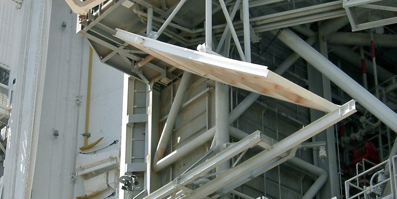
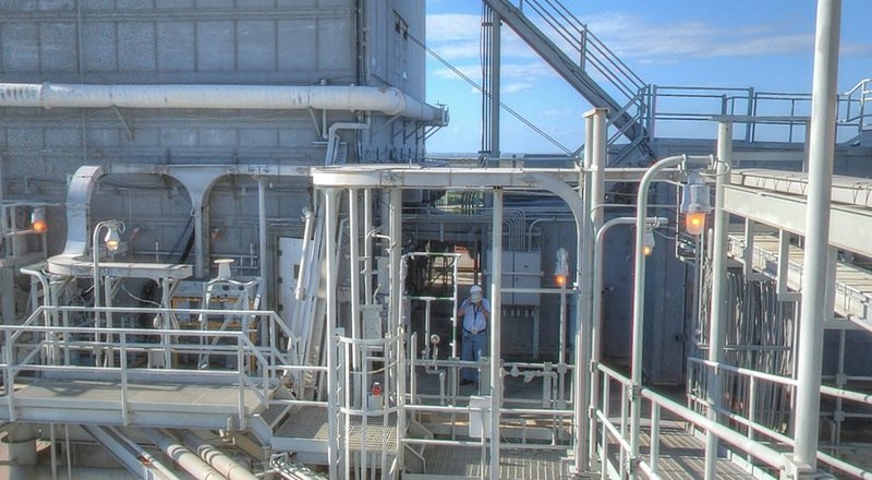
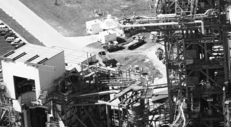
Best to see is it in this STS-6 image. The side wall of the elevator shaft is only at the top of the engine room throughout planar.
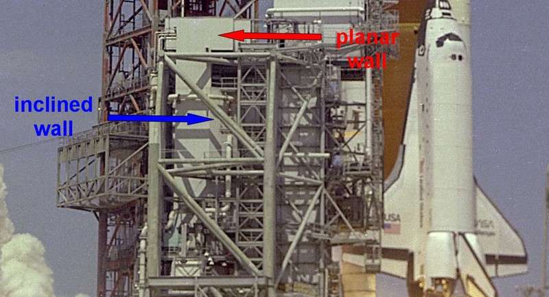
[color=blue]Source: NASA[/color]
Further down this wall runs from the middle slanting forward to the PCR, which can be seen clearly by the changing light/shadow. Maybe it’s also angled shortly in front of the wall. 
Accordingly, the Revell lift shaft is constructed incorrectly. Therefore, the lower doors sit in the shaft unlike the upper door in the front wall of the machine room probably in these slanting floor walls in front of the local staircase, as I have marked blue in this STS-1 photo.
Source: NASA
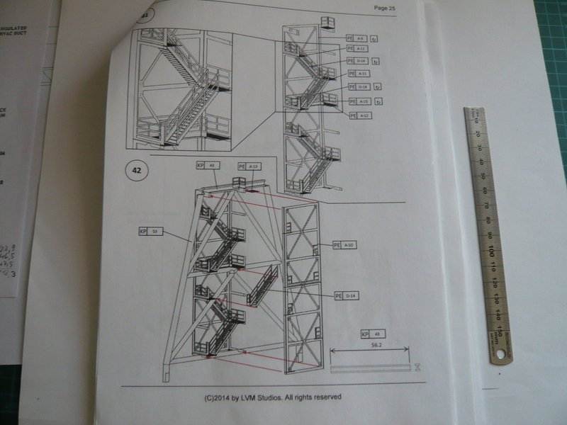
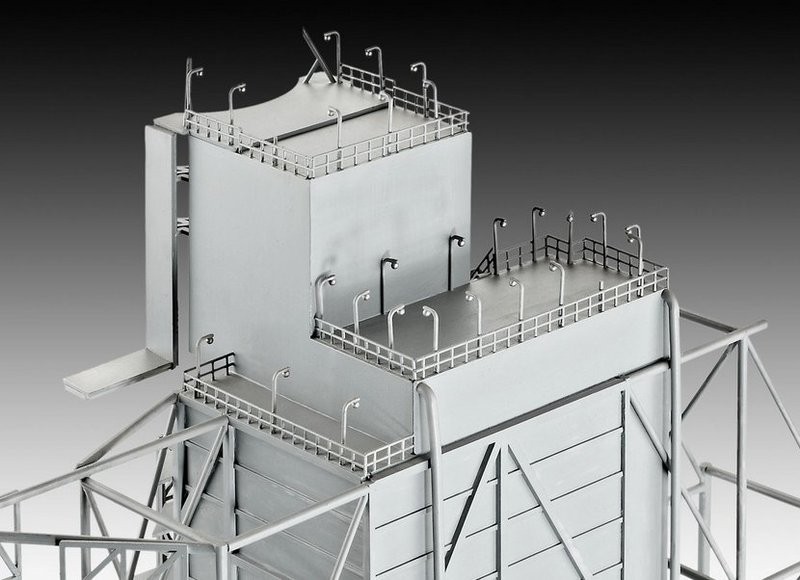
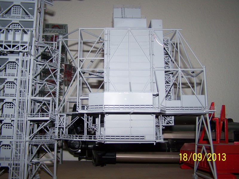
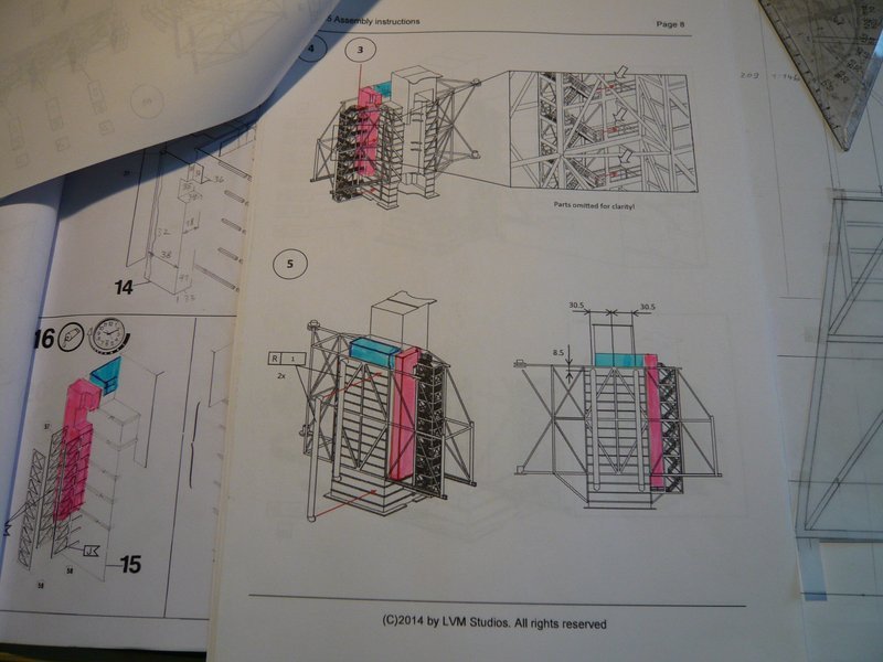
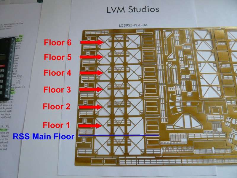
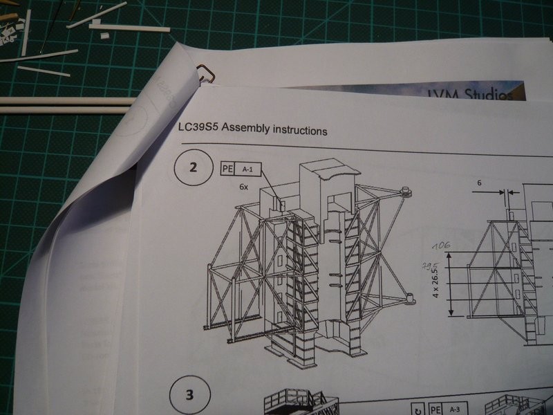
This wrong construction of the elevator shaft LVM Studios have taken over in Detail Kit No. 5 and adapted to their stairwell made of PE parts,  as can be seen here in the LVM building instructions.
And thus to another Revell error. 
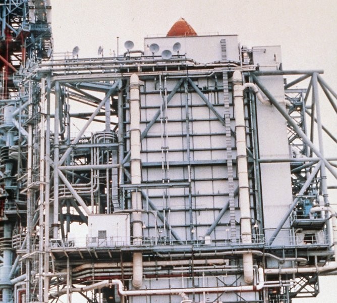
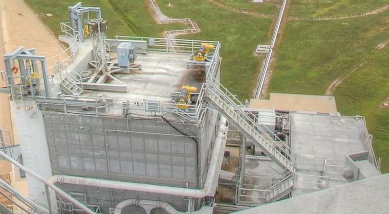
In the lower part of the elevator shaft can be seen six inclined floors doors, and even a 7th door at the top in the machine room. 
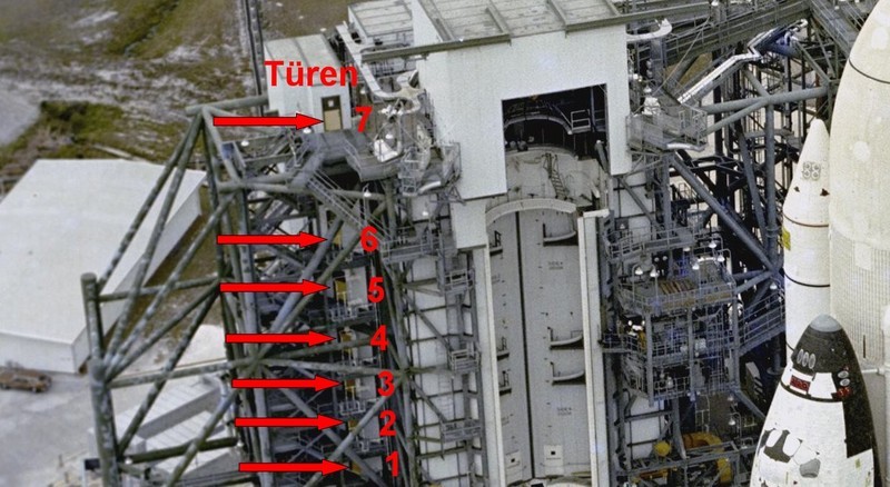
Source: NASA
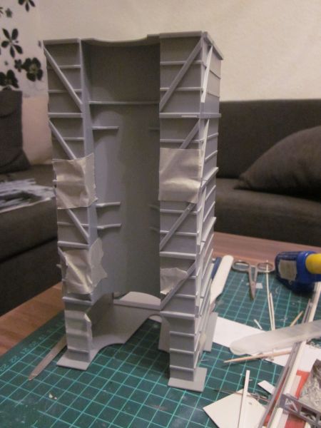
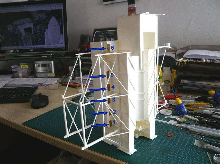
In the Revell kit, on the other hand, there are only five floors with the associated doors in the lower part of the elevator shaft, what LVM has taken over, as one can see here based on the five PE doors in the RSS shell of building, which was built by my friend Thomas Emberger (golgi863) from our German Raumcon Forum, what means that one floor is missing. 
Source: forum.raumfahrer.net (golgi863)
BTW, after I had infected him with my STS-6 project back then, Thomas was building the same Launch Pad 39A but with Discovey STS-41-D. 
Due to the close relationship between our two projects, we had a close and intensive exchange of ideas and experiences for two years, what continually had pushed us and led to new ideas as well as great detailed and problem solutions. 
Unfortunately he died far too early in 2017, which was a brutal lost and turning point for everyone, especially for his family. 
His wife and his son had no direct connection to his project, which is why both of them would have liked me to take over his unfinished project at the time, as they couldn’t do anything with it. 
In consideration of this, after careful consideration, I decided that it would perhaps also be in his sense to at least partially preserve his model building heritage, if I included some of his assemblies such as the already illuminated FSS platforms and the Hammerhead Crane as well the PE Stairs for the tower, etc. would integrate into my launch pad model and thus posthumously document and honor his building skills for everyone to see, which I then have done. 
But back to Revell’s kit, because that’s still not the end of the chain of errors.
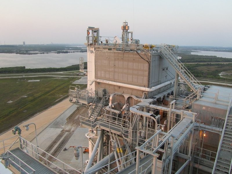
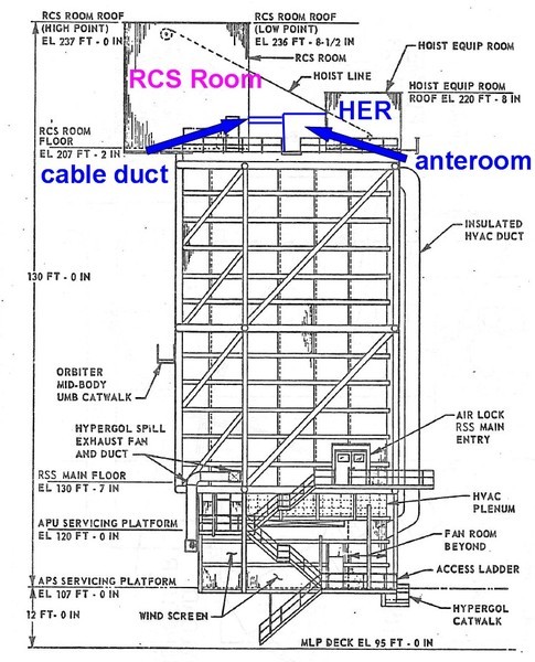
Maybe that’s not been clear enough with the inclined extension of the front wall below the upper cut-out for the angled strut of the support structure.
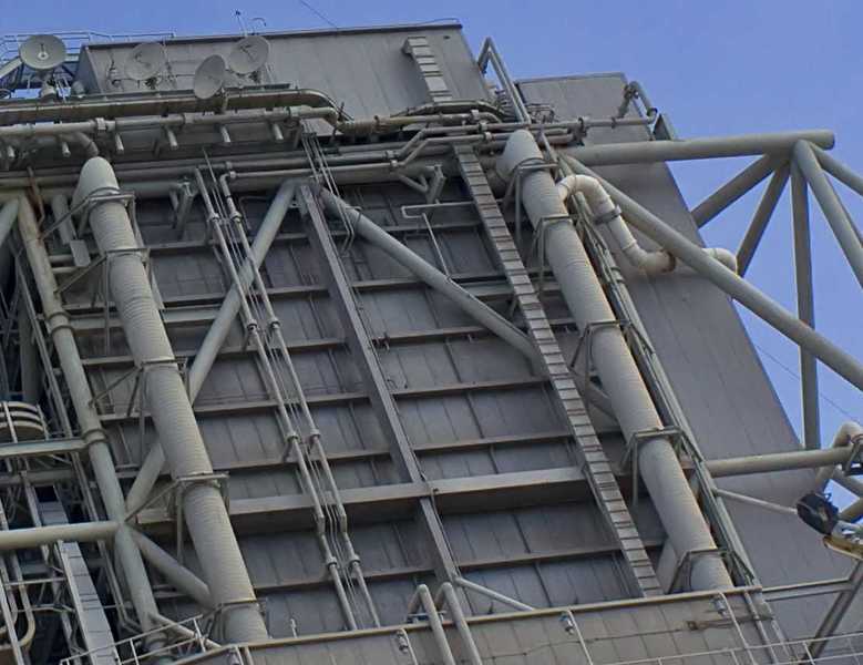
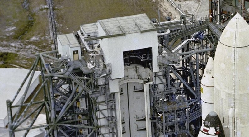
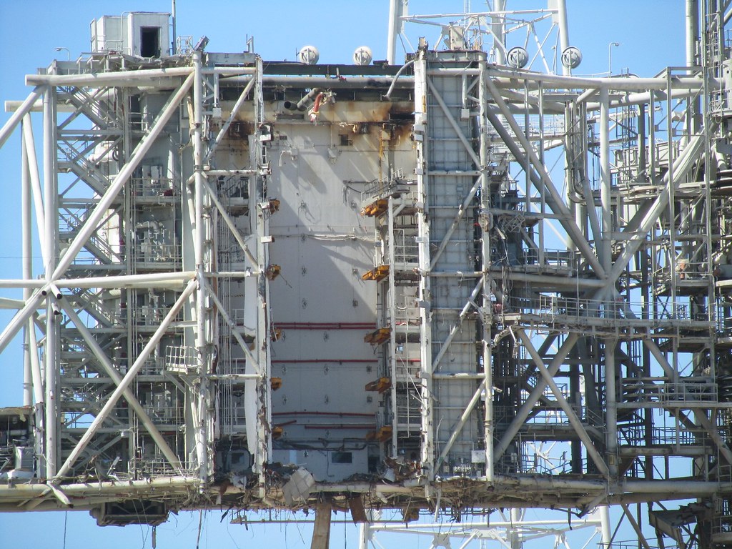
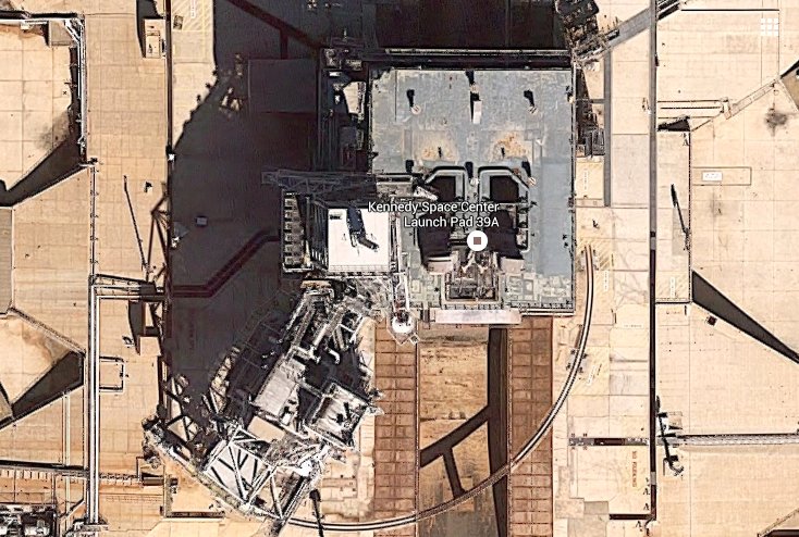
Therefore, I show here again an image of the dismantling of Pad 39B, where you can better see what I mean, because not so much parts are surrounding now.
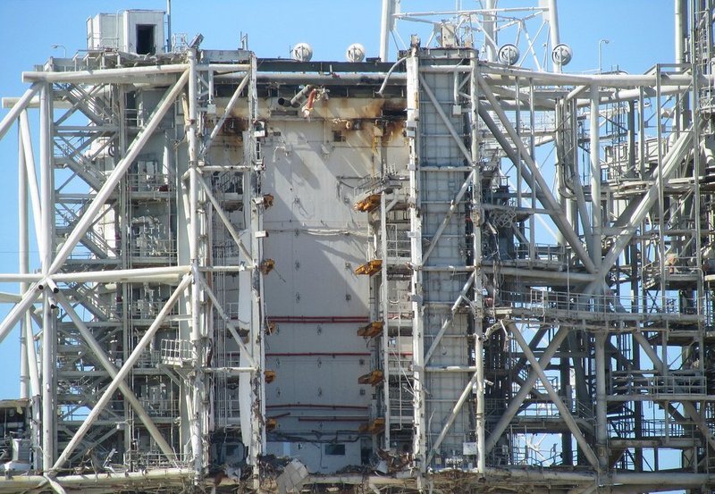
Source: flickr.com (Andrew Scheer)
In my opinion, one can recognize the difference between the position of the upper fully opened and the bottom slightly opened doors in the inclined elevator shaft wall clearly.
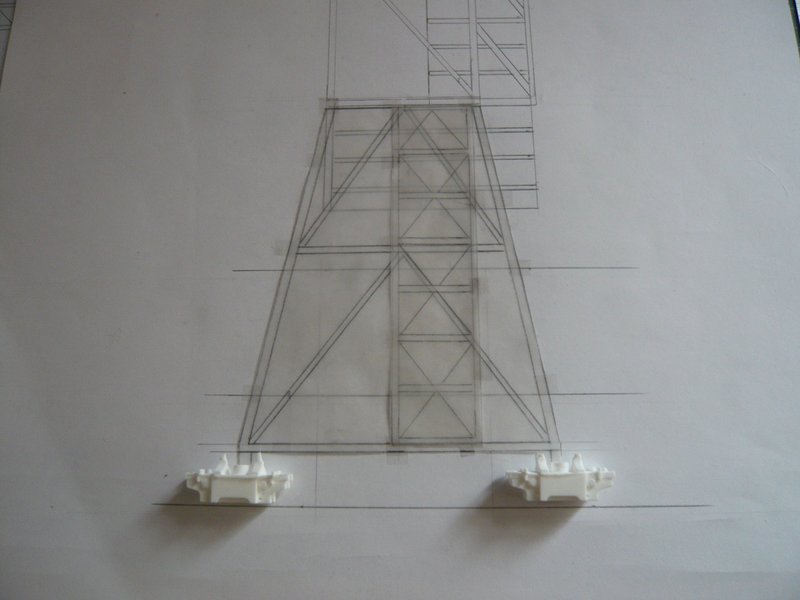
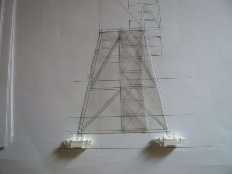
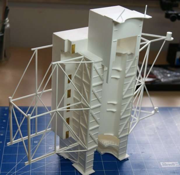
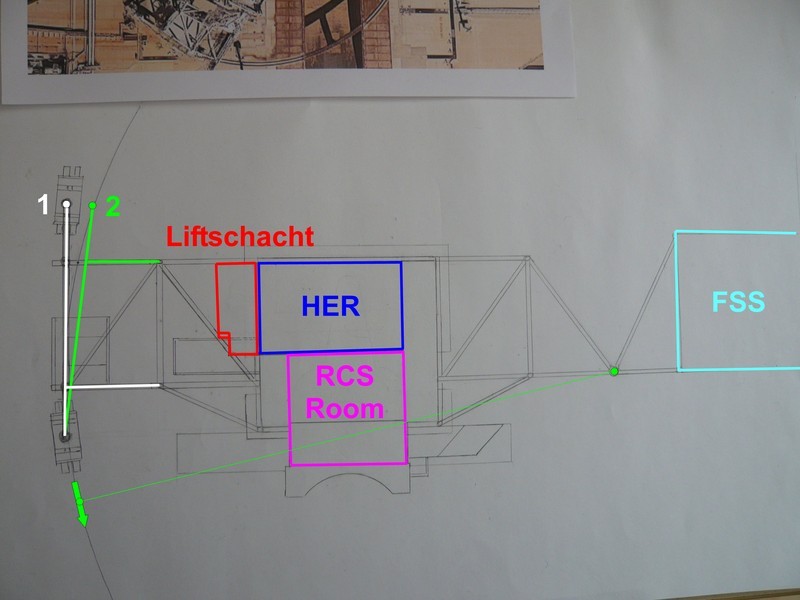
And with the help of this photo I have tried to draw in the lift shaft into the RSS shell of building as it should look like, which then gives a more realistic picture. The doors I’ve omitted for simplicity. 
Now I hope that possible lacks of clarity and doubts could become eliminated, if not, then let me know please.