Outlets are looking great as we would all expect with this level of attention to the smallest detail. Mind blowing work and methods to make it all so realistic.
1 Like
Thank you John for your words of praise, which always do me good and encourage me to keep going even if these details are at the limits of what is possible at this scale. ![]()
![]()
1 Like
Hello together,
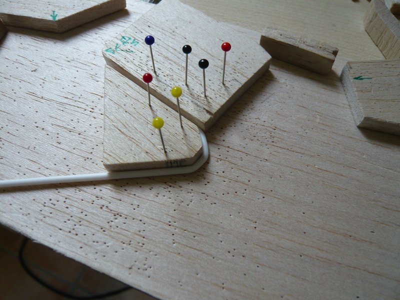
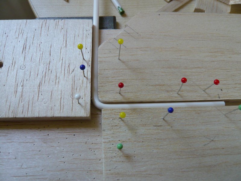
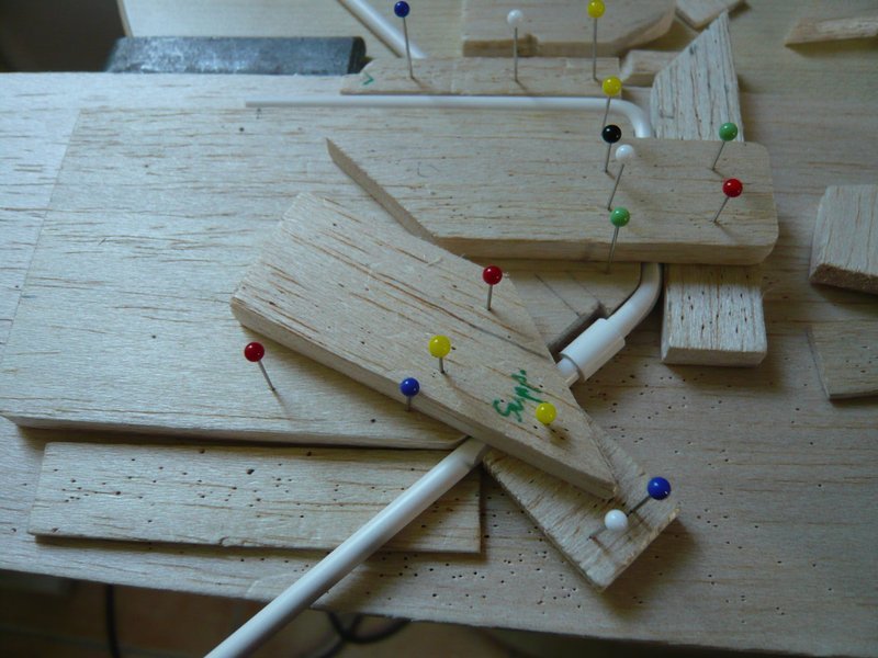
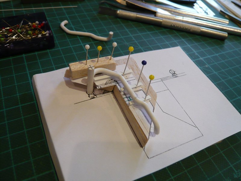
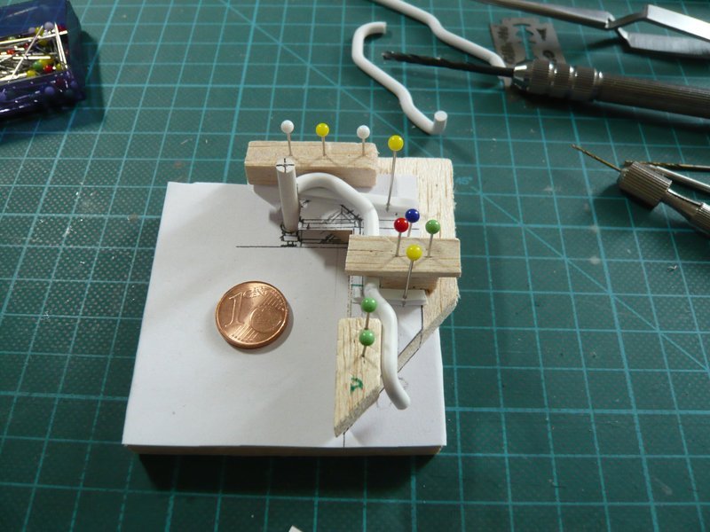
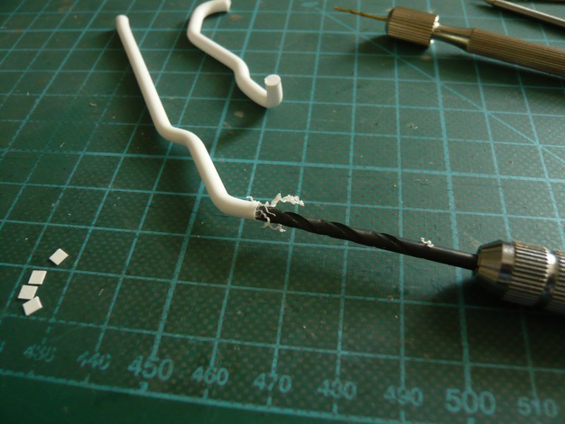
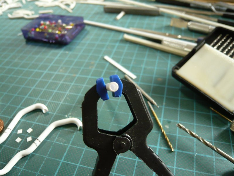
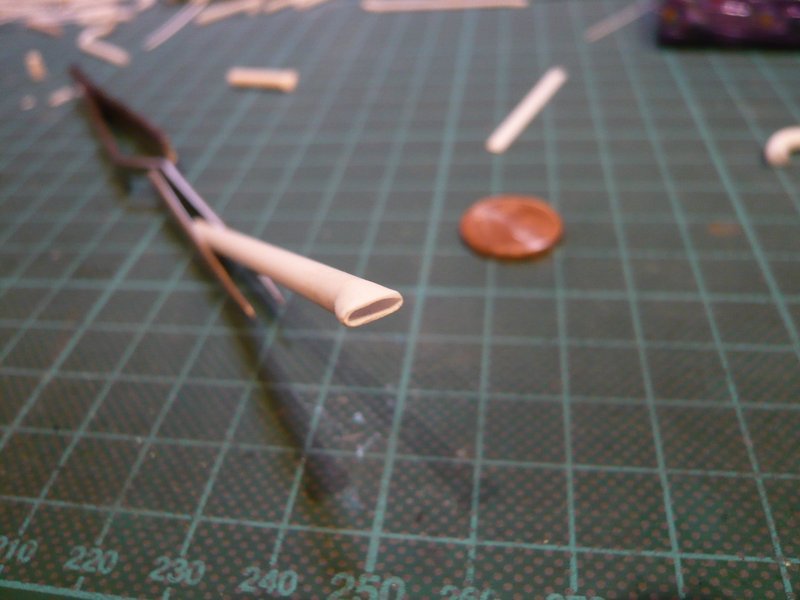
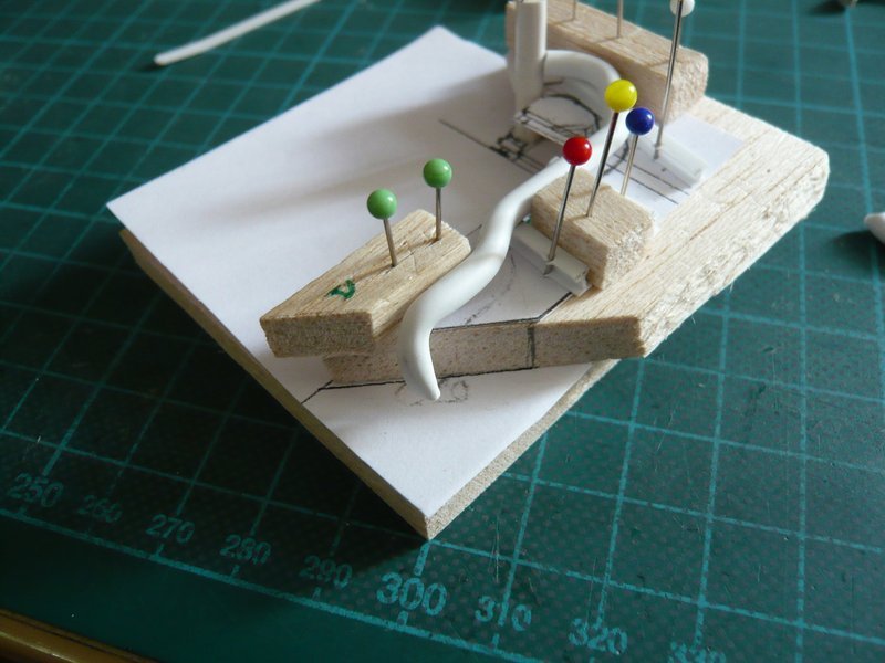
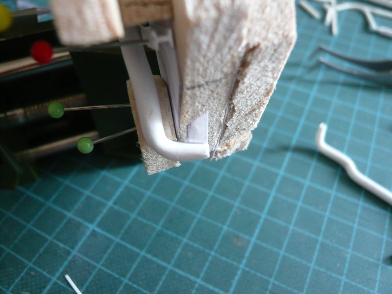
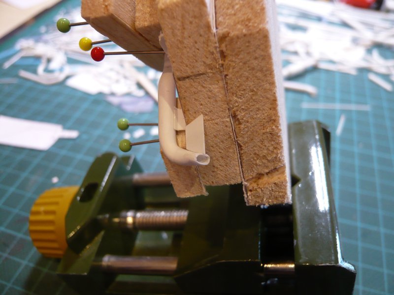
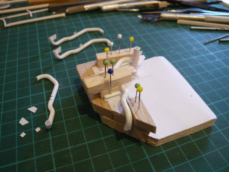
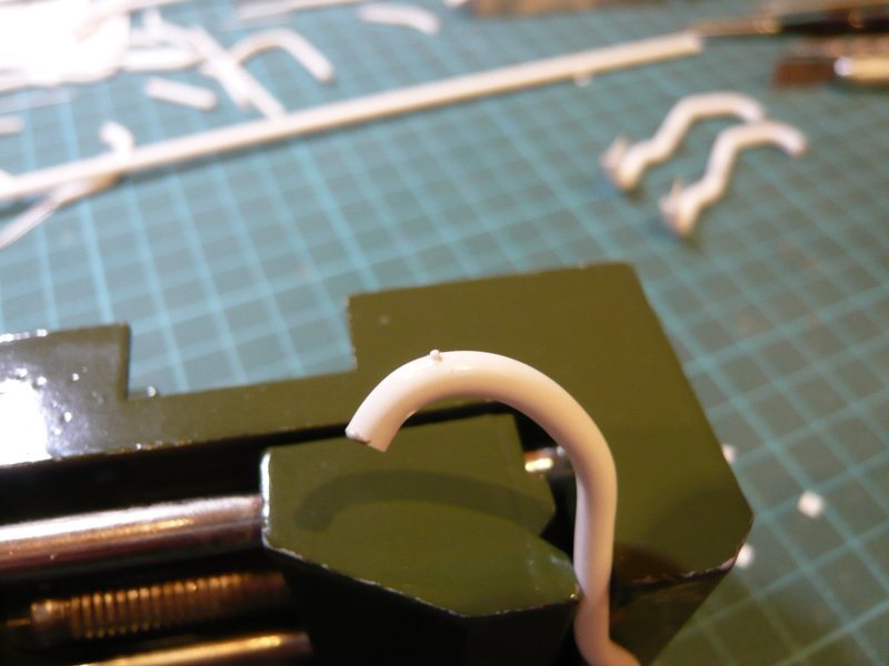
since the prototype anyway already is under the weather and does not come into consideration for the final assembly, I have experimented with him anyway and tried the subsequent bending of the transition to the ring line, in the hope that he would survive it. ![]() The bending is therefore not easy, because it has to start behind the flat bow directly what makes the clamping somewhat difficult.
The bending is therefore not easy, because it has to start behind the flat bow directly what makes the clamping somewhat difficult. ![]() But two pins have been given sufficient support.
But two pins have been given sufficient support.

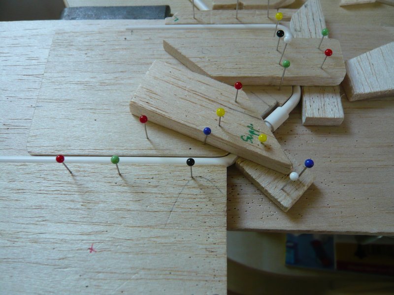
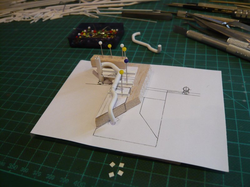
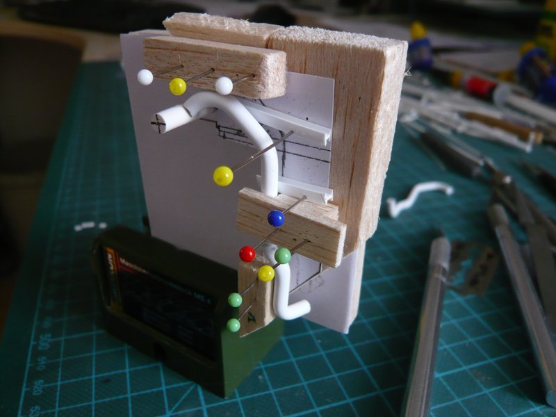
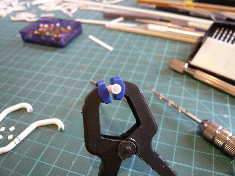
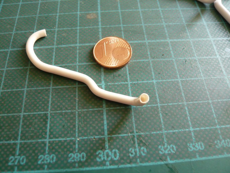
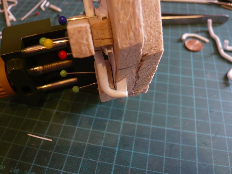
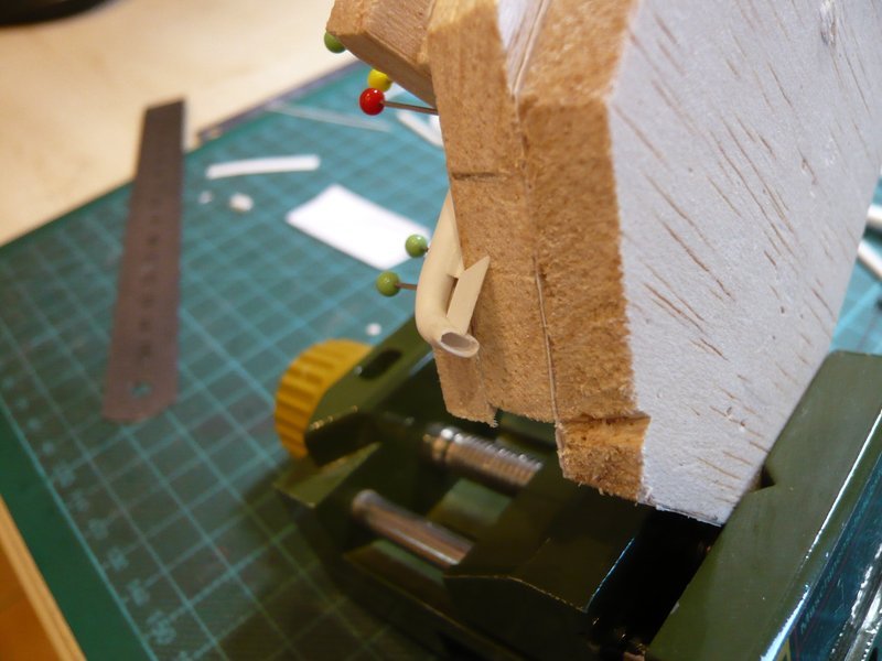
And then I have gently heated up this bending point and slowly bent down the rod at the onset of softening what went but easier than I thought. ![]()

And since the adhesive point has withstood,

I could also take measurements up at the ring line to remove the rest.


And here is the result.


So only was missing the test on site.


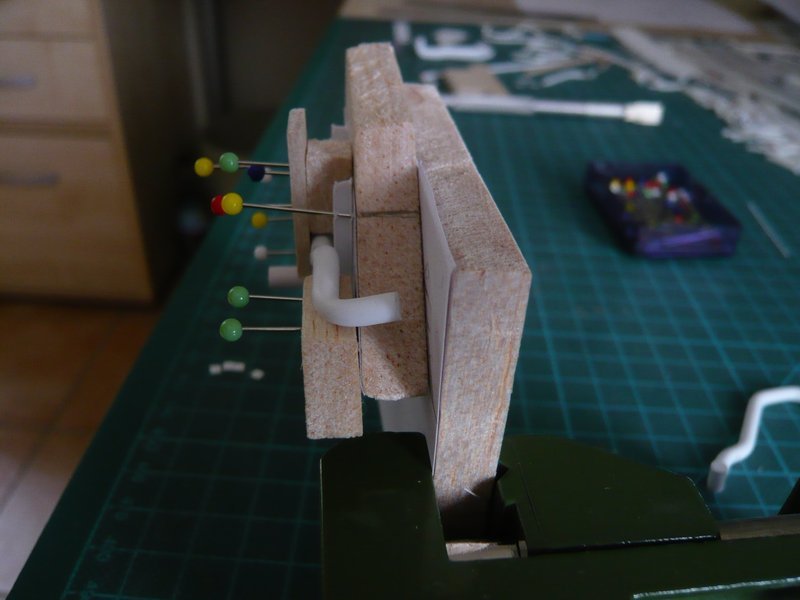
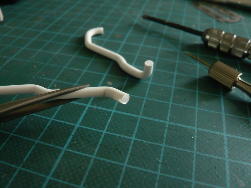
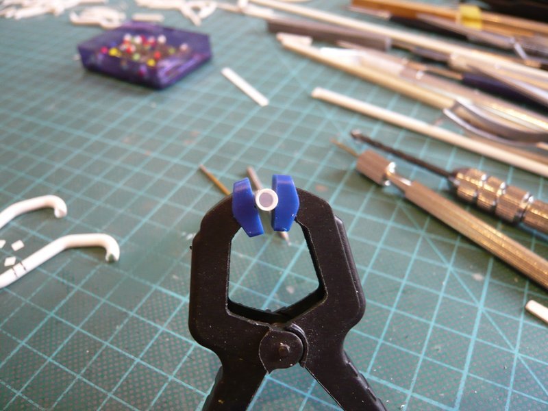
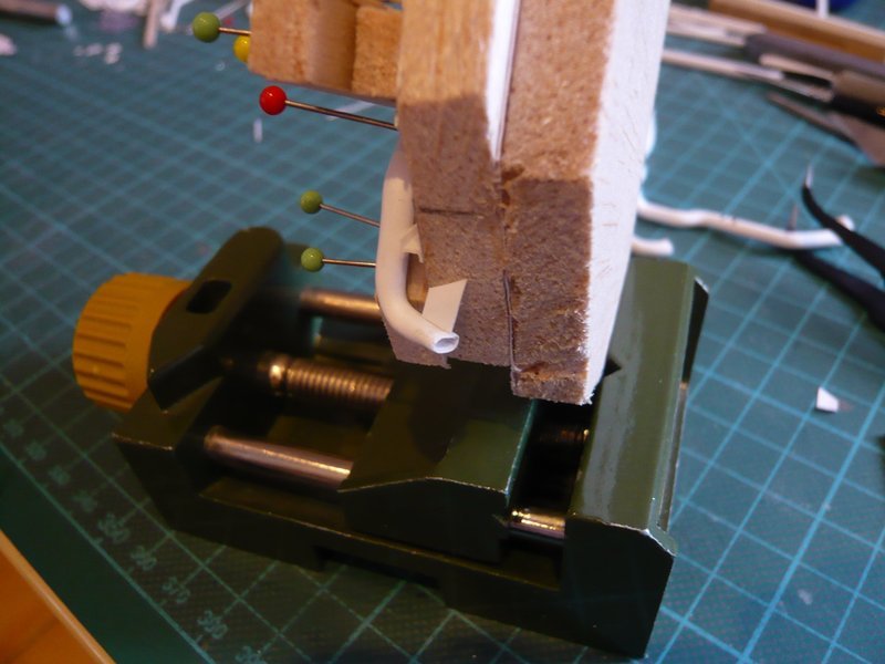
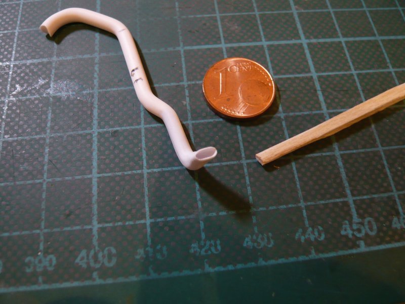
This looks already quite usable for the moment, but the vertical part does not align against the shaft wall, but protrudes a bit too far at the top. The reason is that the flattened part of the bow is still a bit too long, what I had already suspected, ![]()

which is why a little fine-tuning is necessary there. ![]()
![]()
4 Likes
Hello everybody,
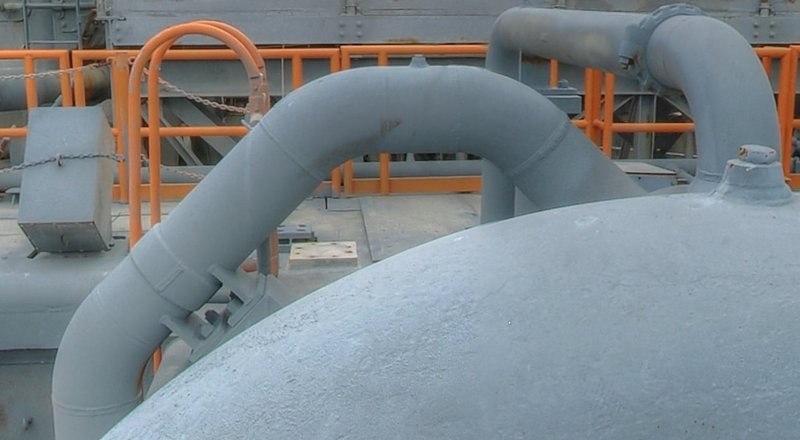
I took a closer look at the two 12’’ outlets ![]() and corrected their shape based on this cool perspective, especially since the upper flat arch part was still a bit too wide for me.
and corrected their shape based on this cool perspective, especially since the upper flat arch part was still a bit too wide for me. 
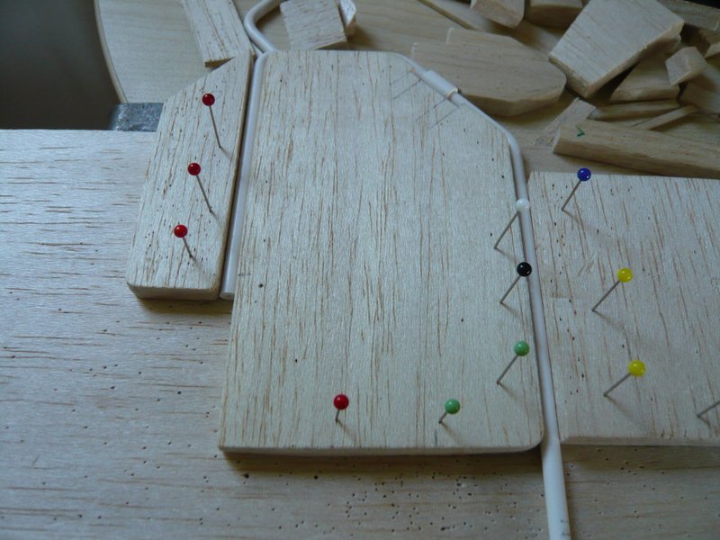
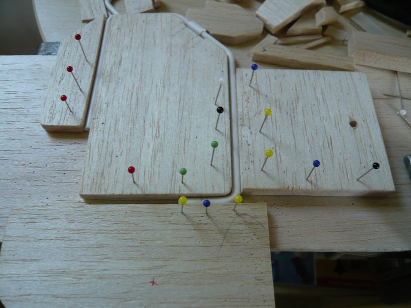
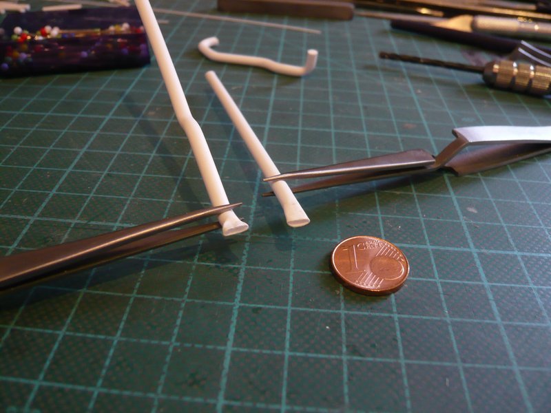
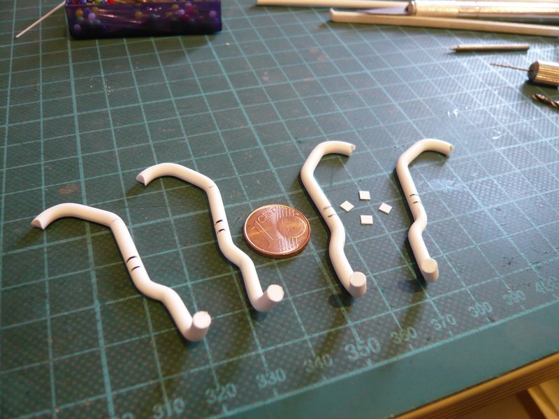
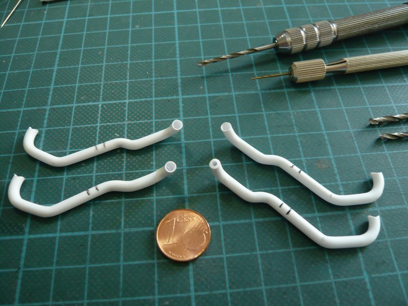
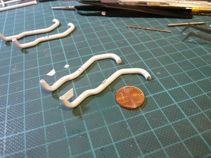
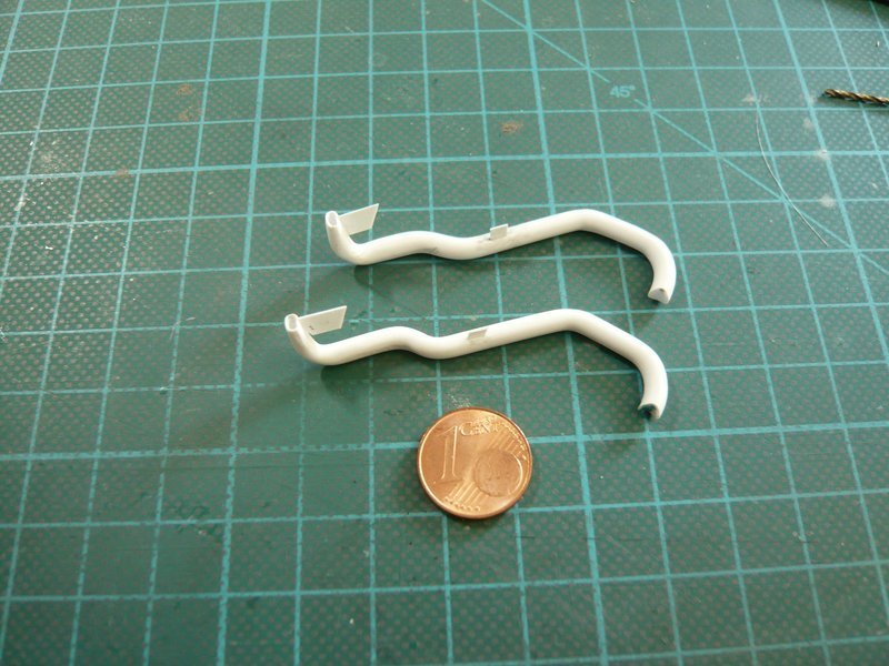
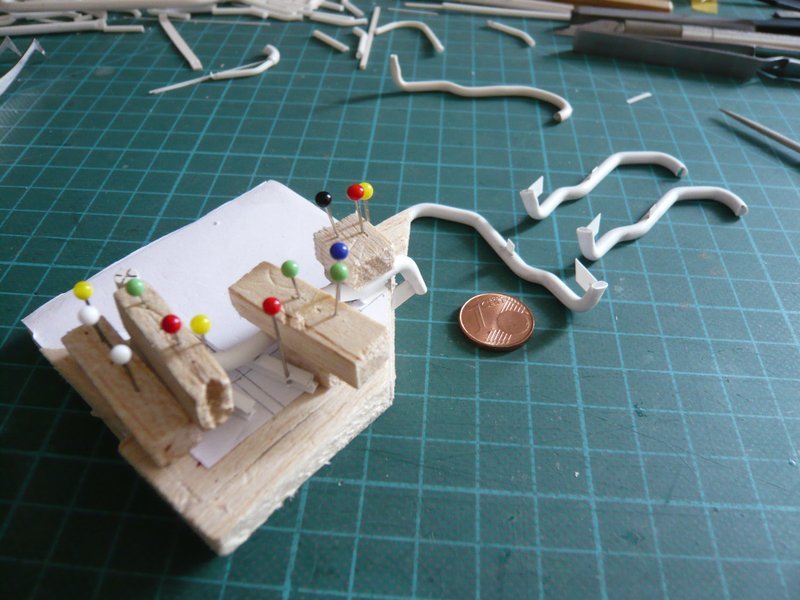
I reduced this image as a new template until the 12’’ exit corresponded to 2 mm. And on it you can see my previous exits. On the right is the first prototype with the glued break point, where the flat arch part is still clearly too wide. ![]()
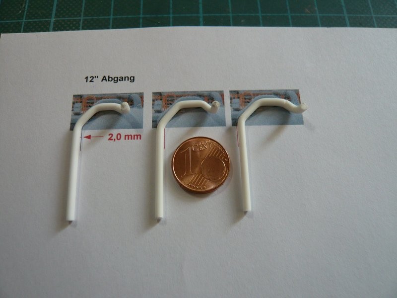
The next arch in the middle is better, but still a bit too wide, and the left arch then matches the template quite well. ![]()
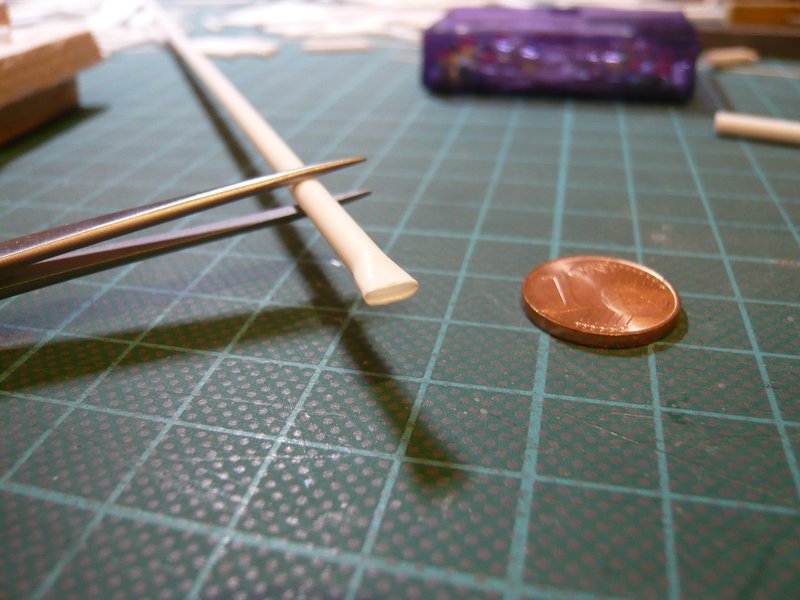
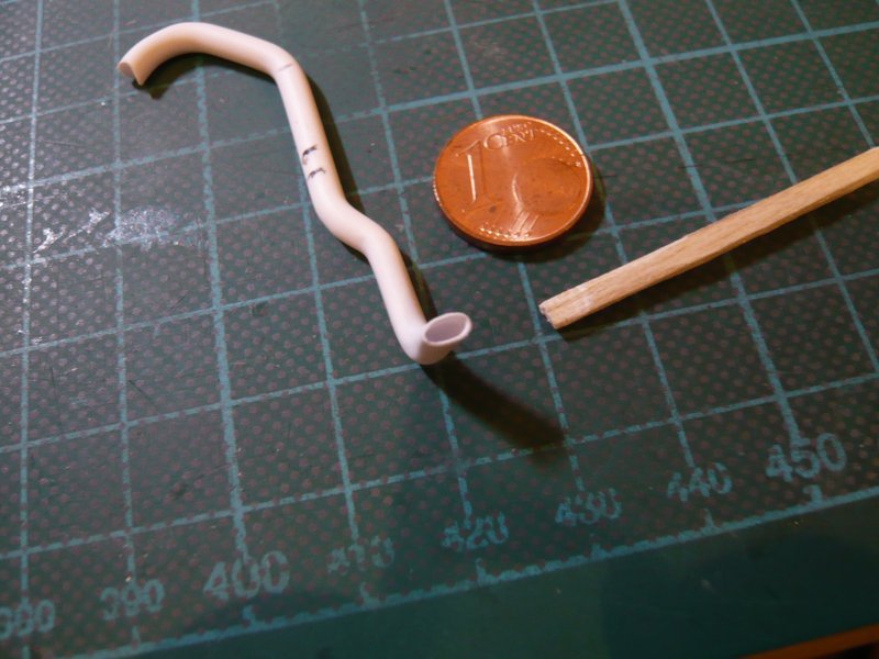
Now quickly back into the pipe pleasure with the modified Balsa template whose upper flat bow is still somewhat narrower. ![]()
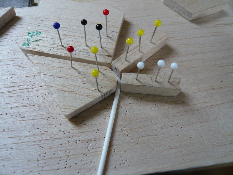
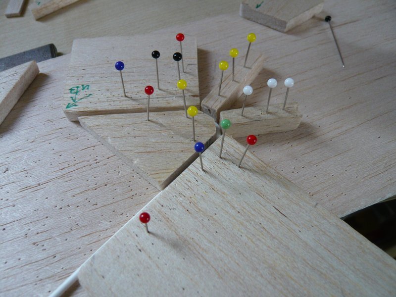
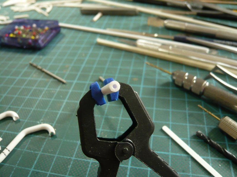
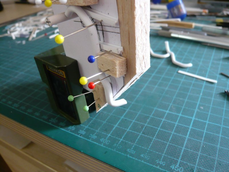
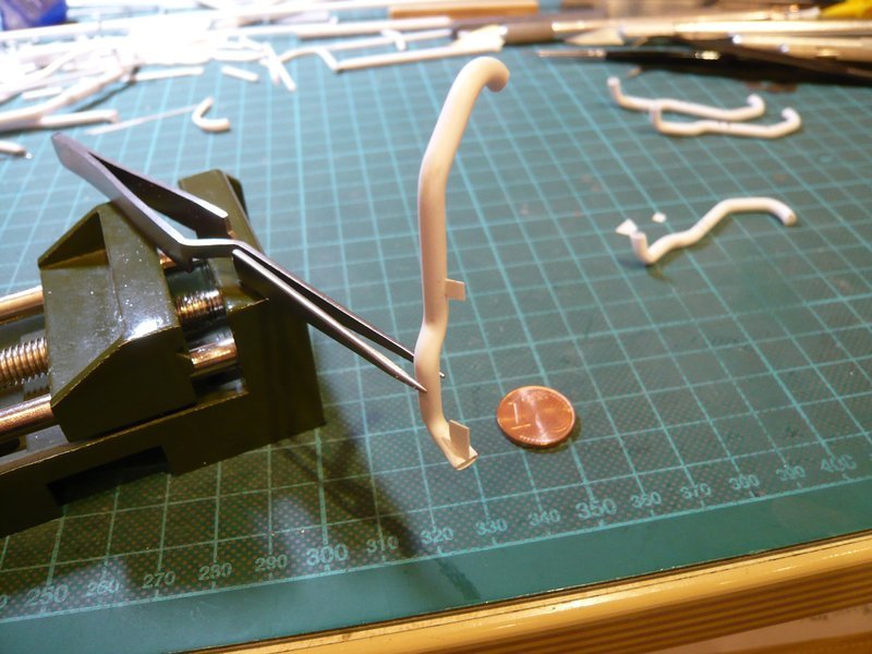
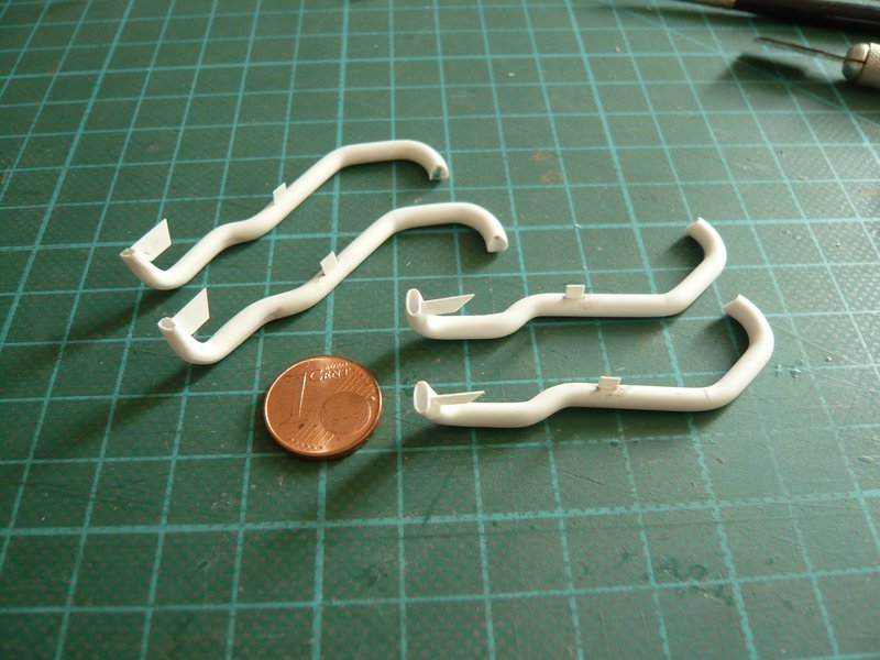
Important for the next 45° bending is at first the fixation of this slant and the separate extension of the abutment face, as these short pieces otherwise don’t stay straight, but would rather become rounded. ![]()
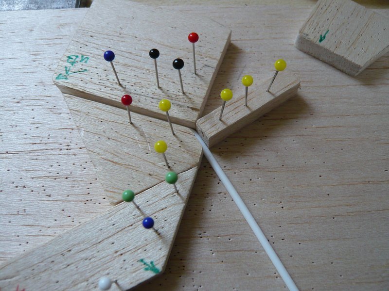
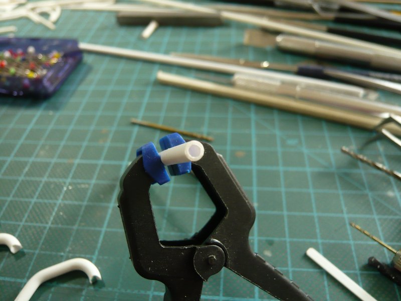
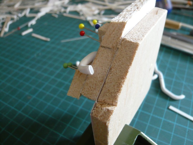
To avoid this also during the following bending, even this small flat bow must be specially fastened previously. ![]()
And after bending I have preventively heated one more time in the clamped state.
After that all sides should fit closely on the template.
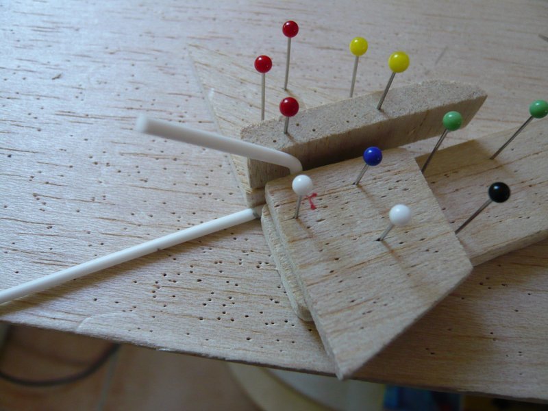
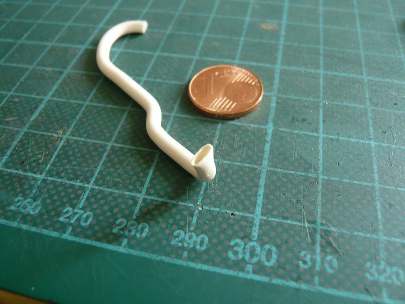
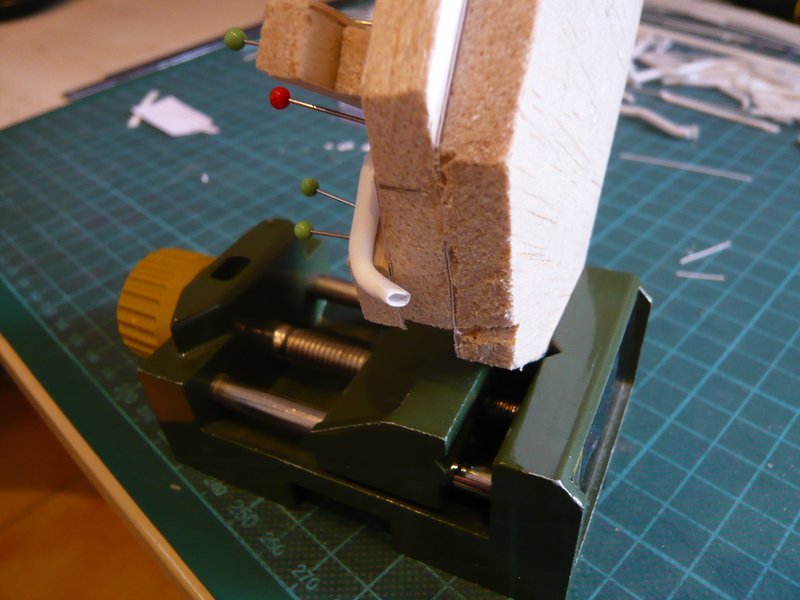
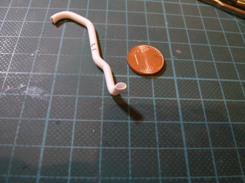
After that follows the last one, but at once the most difficult bending of the transition to the ring line around a relatively tight radius, because an exact positioning of the rounding template is important, but this is more or less a matter of feeling. ![]()
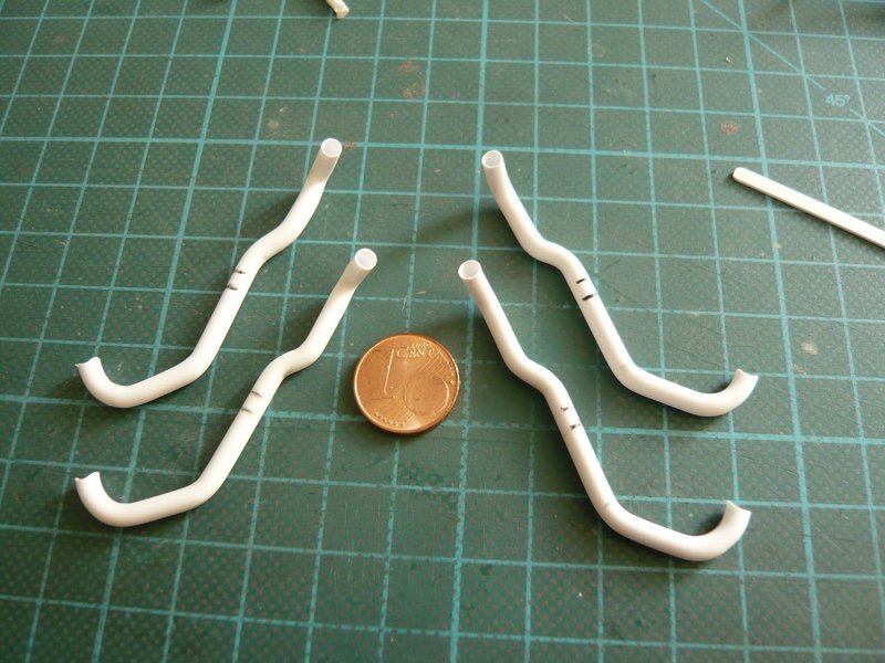
And this is the result.
Now the test must show whether or how well the outlet fits. And that now looks already totally better than before. The upper bow is flatter and lies slightly lower than that of the forward 18’‘/12’’ outlet,
and the support still has some space to get closer. ![]()
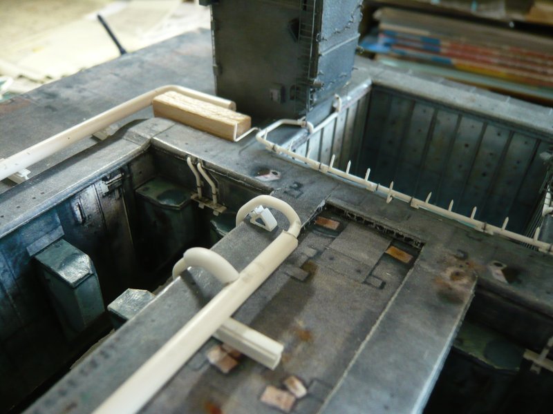
Meanwhile, the front outlet has been slipped down a bit, because the Pattex power subsides, be that as it may! ![]()
So much for today. ![]()
![]()
4 Likes
Hello everyone,
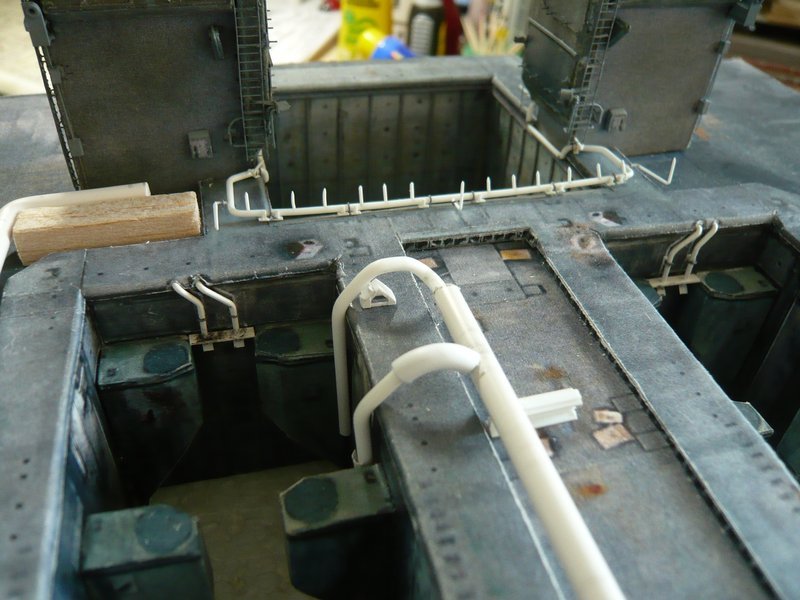
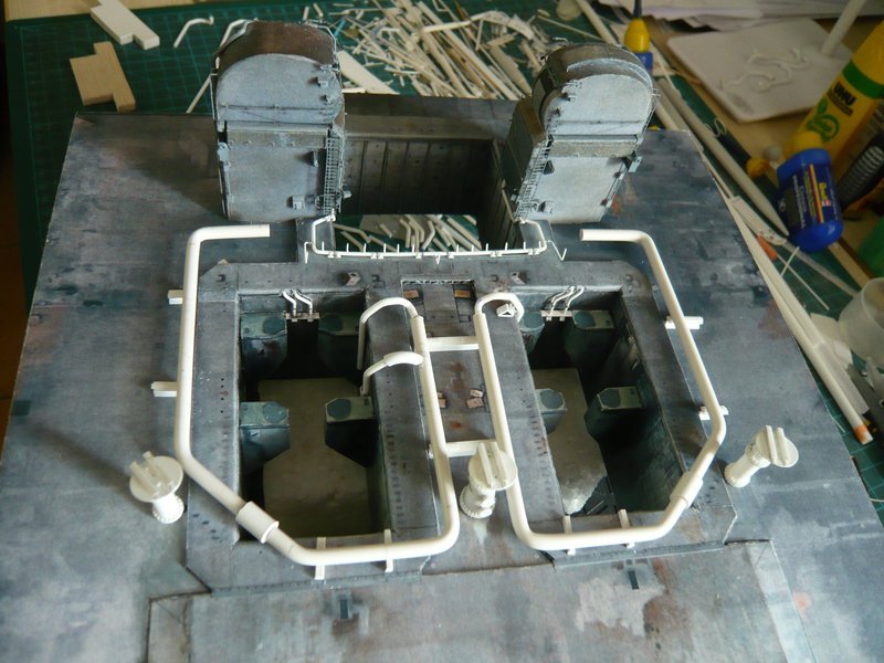
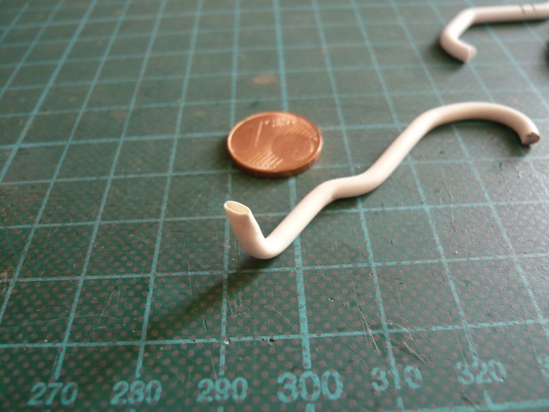
today for a change I have bent the missing second 24’’ ring line (Ø 4,0 mm). ![]()
While the thin 12’’ outlets (Ø 2,0 mm) soften relatively quickly, this thicker rod must be reheated a little longer before one can bend it easily.
Otherwise it was the same procedure again, as you can see, whereas the roundings this time even have become better than at the first ring line, this makes the exercise. ![]()
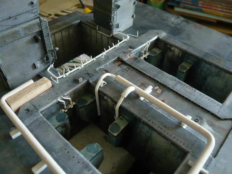
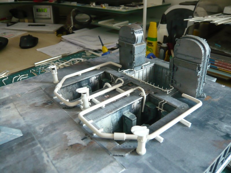
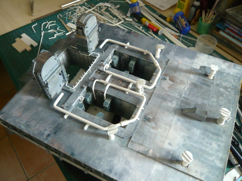
And this is the next test, this time again with the Rainbirds, to round out the picture,
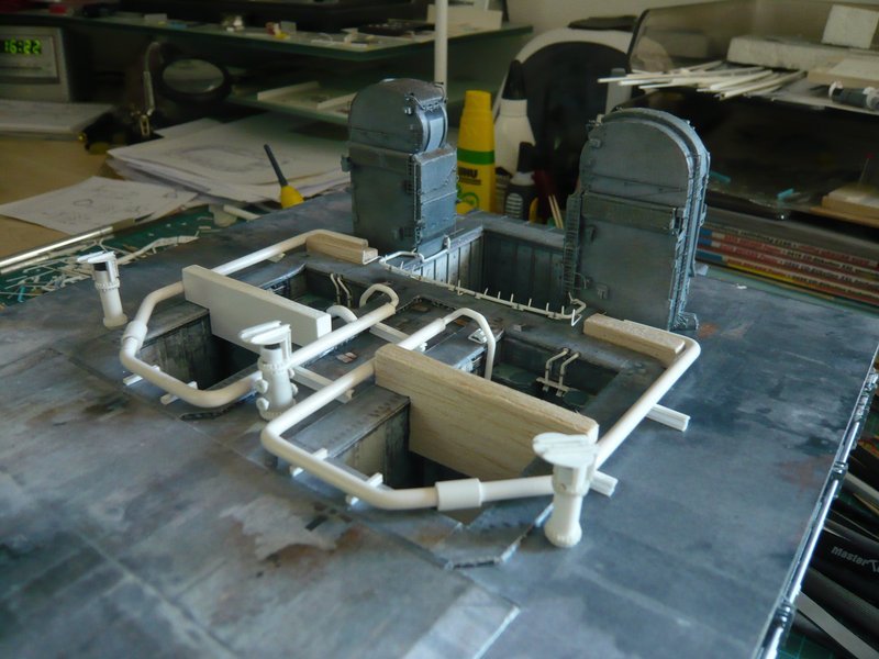
and here without the annoying placeholders. ![]()
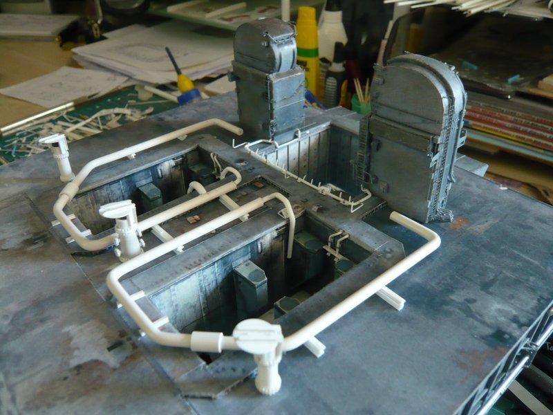
And so the upper deck is slowly filled by the SSWS, what looks ![]() .
.
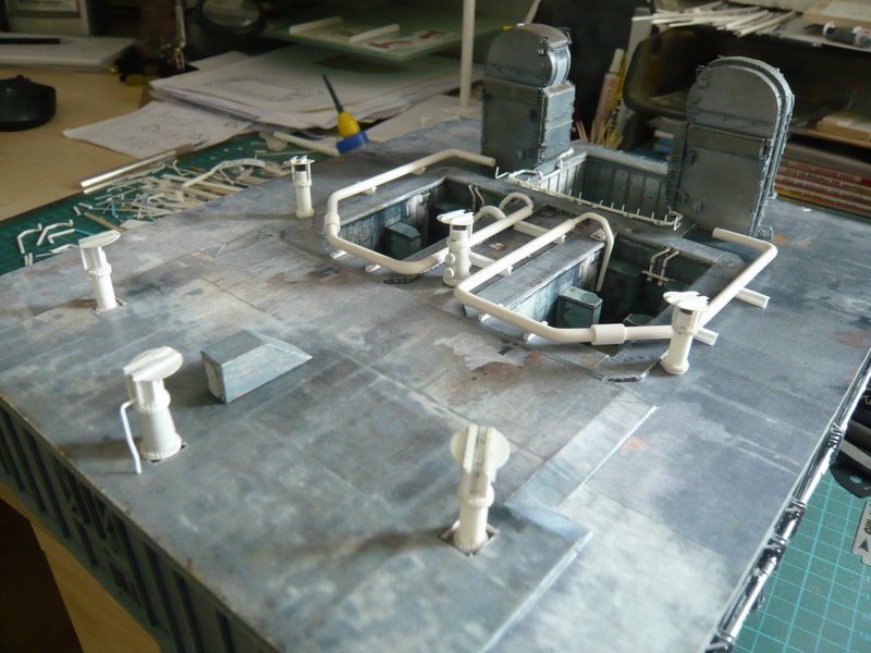
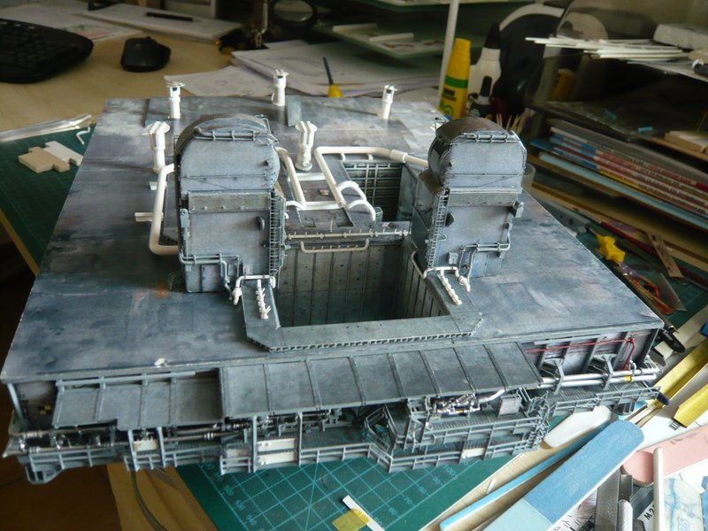
And finally still a total view from the front. ![]()
That’s it for today. ![]()
![]()
5 Likes
Magnificent and monumental ![]()
![]()
![]()
Thanks my friend,
I’m glad you like it, enjoy! ![]()
I’ve been following your build and it is incredible. Your skill and precision is unworldly.
How do you heat up tubing for bending?
Thanks Barney for your nice compliments,
luckily I don’t have to bend any pipes, but can use round rods for the pipes, since no water needs to flow. ![]()
And the round rods can be bent using a hot air gun, as you could see, you just can’t overdo it, otherwise they’ll lose their shape. ![]()
Plastic pipes would either have to be filled with a core, otherwise the bending point won’t be round or could kink. ![]()
![]()
2 Likes
Hello everyone,
today I want to come back to the 18’’ outlets, which indeed still have no outlet openings. And also lacking even the little supports with which they are attached to the SRB supports. ![]()
That are these small metal sheets here,
and then these here below the SRB-supports immediately above the outlet openings.
While the supports in the first image are simple square Styrene plates (2,5 mm x 2,5 mm x 0,3 mm), the lower supports have a trapezoidal shape because they sit on the slant of the SRB supports and on the flattened outlet openings. And this results in two little problems, one being the difficulty of determining their dimensions, and closely connected their mounting on the outlet openings below the support slants. ![]()
For the dimensions this image was relatively well suited. It can be seen that the outlet opening and the trapezoidal sheet ranges up to about the middle of the SRB support.
Accordingly the size of the support is about 3,7 / 2,5 mm x 3,7 mm x 0,3 mm.
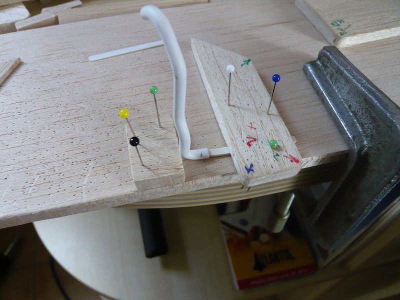
For the adaptation and assembly of these supports at the outlets, I have modified my previous mounting template for the tapered 18’‘/12’’ outlets to the following Balsa jig which has the shape of the SRB supports. ![]()
The support is made of 8 mm Balsa and thus corresponds to the thickness of the SRB support. In the base plate beneath sits the 24’’ ring line for an exact alignment of the 18’’ outlet. As spacers I have used 2,5 mm H beams (Evergreen).
Now I have fixed the location of the outlet from both sides and from above, so that it can no longer slip. ![]()
And in the gap between the support and the outlet end can now be adapted the trapezoidal support plate and also glued later.
But previously the outlet opening must be hollowed and flattened out. ![]()
![]()
4 Likes
Great update and I just love those pipe jogs … Brilliant!!
Thanks John for looking in on me again, ![]()
I don’t lack good ideas, ![]() but the amount of clamping effort involved is already crazy,
but the amount of clamping effort involved is already crazy, ![]() but it wouldn’t work without it.
but it wouldn’t work without it. ![]()
![]()
1 Like
Hello everybody,
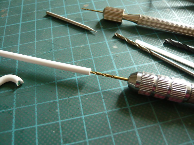
Therefore at first I have tried to pre-drill the outlet end as centrally as possible with smaller diameters (up to 2,4 mm), but this is not so simple and is slightly shifted again. ![]()
After the final drilling with Ø 2,8 mm, the wall is rather thin and unfortunately unequally thick,
which is unfavorable for the subsequent warm-flattening of the opening (on the left).
Another possibility (right) would be to use a drilled Styrene pipe (3,2 mm), of which the wall would be indeed more uniformly, but slightly thicker, which would be acceptable. ![]() The form itself certainly looks cleaner.
The form itself certainly looks cleaner.
Of which now however still had to be cut off a short end piece and to be glued at the shortened outlet end, as well as additionally refinished, which would be an additional fiddling again. ![]()
Meanwhile, I’ve bought a drill with Ø 2,5 mm which hopefully is better suited, let’s see … ![]()
Finally, I have marked nor the positions of the upper support metal sheets.
Well then until soon. ![]()
![]()
4 Likes
Hello everybody,
now missing only the outlet openings that I wanted to try again. ![]()
The difficulty is, as I said, the central drilling, which you cannot do it immediately with the final diameter, which is why this time I drilled a dummy (3,2 mm) in smaller gradations. ![]()
After center punching as central as possible I first started with Ø 1,3 mm, specifically about 6 mm deep, that means gradually in and out, so there is no chip congestion. ![]()
And that looks already pretty centrical. ![]()
Thereafter followed Ø 2,0 mm,
Ø 2,3 mm,
Ø 2,5 mm,
and finally still a slight countersinking with Ø 2,7 mm for reduction the visible wall thickness, just because of the optics. ![]()
And then I have briefly heated carefully and gradually slowly flattened the front end (about 3 mm) with a core (0,75 mm x 2,5 mm) down to 1,7 mm height, but not this way … ![]()
And that can be quite impressive, right? ![]()
And therefore I can probably now also venture to the final outlets, hopefully it’ll work also as well then. ![]()
![]()
5 Likes
Hello everyone,
I have made a final test on a real component and thereto used my first 18’’ outlet prototype, which still was lying around and anyway is good for nothing. He still had Ø 3,0 mm and was due to the bendings no longer circular at the end , but came just right as a dummy. ![]()
Its end I have drilled out to Ø 2,5 mm,
and then flattened, as usual.
As can be seen, one can scratch the outlet opening also directly at the bent outlet.
Therefore I can now also get down to business with the four final outlets (Ø 3,2 mm). ![]()
And this I have implemented now, in hopes that it will fit somehow. ![]()
First, I have drilled out the final four 18’’ outlets, as already described.
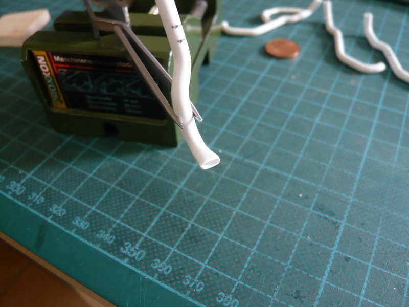
So far so good, and now came the cautious forming of the outlet openings with the help of the Proxxon Gun, ![]() for what I have inserted a core.
for what I have inserted a core.
Nevertheless, one must be extremely careful during heating, so that the thin-walled opening is not shrinking suddenly. ![]()
And how the subsequent fitting shows, the position of the opening under the Balsa support looks quite passable. ![]()
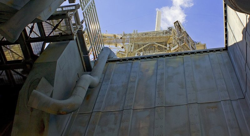
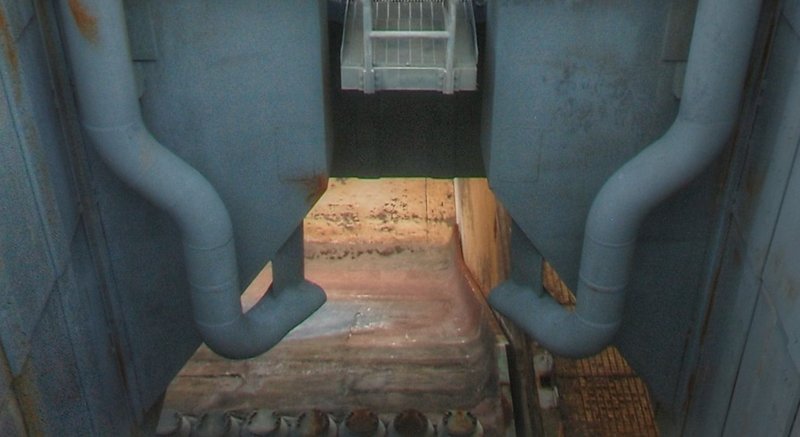
And now to the lower support plates, which can be seen in this panorama of the STS-134 on the MLP-2.
First, I have tested my estimated size with a paper dummy, which was still a bit too small. ![]()
With the adjusted support plate of 0,3 mm Styrene it looks much better already. ![]()
So both plates can be glued now on the outlets in place.
But before the lower support plate was once more modified slightly and now stands vertically, ![]()
and then it was glued above the outlet opening.
And then came still the upper support.
That’s it for today. ![]()
![]()
5 Likes
Hello everybody,
but first times still an addendum to the current state of the first two 18’’ outlets with the support plates.
And for the flattening of the outlet openings on the two other outlets I have my method still slightly modified. ![]()
The opening can in fact even be better formed when one first uses a balsa rod which is flattened out gradually during heating,

after which I’ve used one of the new opening adapted core.
And this gives a nearly perfectly shaped opening. ![]()
Because of the different running lower curvature of these two outlets I had to remodel my Balsa clamp jig laterally reversed for adapting the lower support plates.
Thanks for watching. ![]()
![]()
6 Likes
Hi folks,
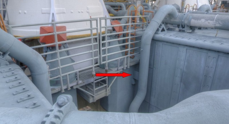
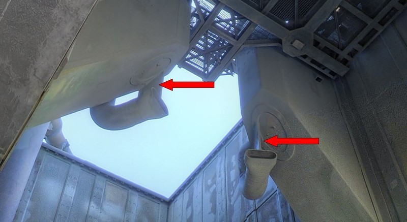
here is still a question to the expert round, what do you think wherefore these screwings are good for, which are located at all outlets (6’’ - 9’’ - 12’’ - 18’') of the SSWS? ![]()
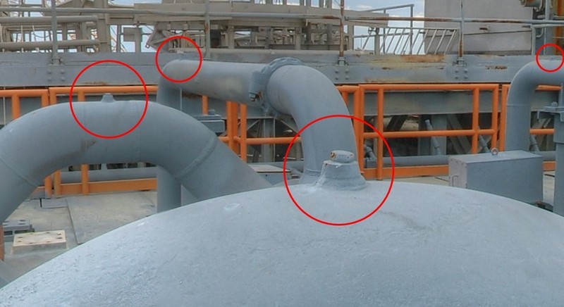
Of which there are a total of 18 pieces, ![]() if I’ve counted correctly, although here some are covered.
if I’ve counted correctly, although here some are covered.
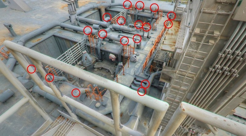
Are these possibly vent openings or inspection ports? ![]()
![]()
5 Likes
I’ll hedge my bets & say dual-purpose ![]()
2 Likes
Wait a minute…I thought I was following a modeler but what the heck all this plumbing going on in here?
Mr. Lets get this right… are you a model and scientist or a plumber? ![]()
1 Like
Thanks Tim and Mike, but don’t panic folks. ![]()
But as you know, I’m not just building a Shuttle, but a Diorama of the entire LC-39A Launch Complex, and the SSWS is part of that, no ifs or buts! ![]()
First of all I thought about vents, but meanwhile I think, that vents shall probably not come into consideration, because the SSWS pipes are only during the launch under pressure. The rest of the time the entire system is open, from the two 36’’ feed pipes in the SRB exhaust holes
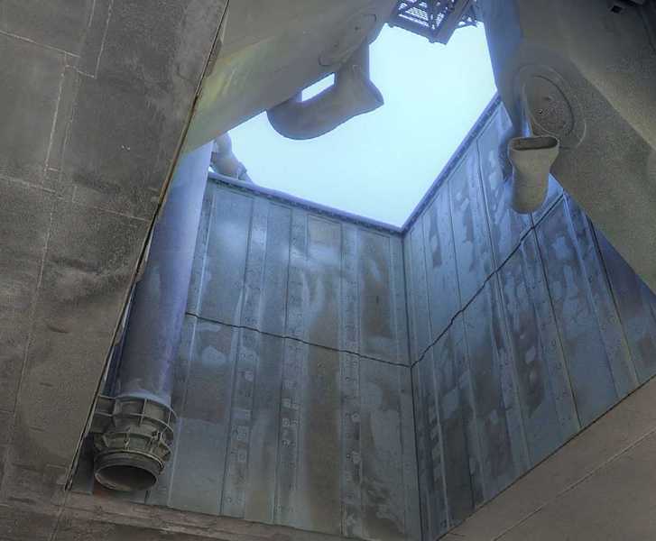
to all outlet openings of the two ring lines.
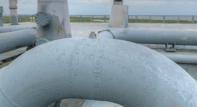
Therefore I rather think that these openings are probably some sort of inspection ports for access for Mini Cameras periodically to check the pipes for cracks and wear. Because at these pipe-bends the stress as well as the wear of the pipes are greatest, this makes most sense to me in terms of Technology assessment and Tribology, wherewith I was also dealing with long time ago … ![]()
Be that as it may, I’ve tried to scratch these ‘nipples’. ![]()
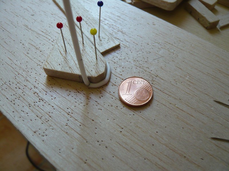
As already indicated, the nipples are relatively small in my scale (1:160), only about 0,4 mm/0,2 mm in diameter and about 0,4 mm high. ![]()
If one would be pretty exactly, one might poke a brass rod Ø 0,2 mm into a brass tube Ø 0,4 mm with 0,09 mm wall thickness, as one can see here.
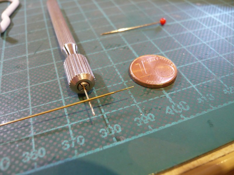
But the tiny “screw” on the right side is hardly to be seen still.
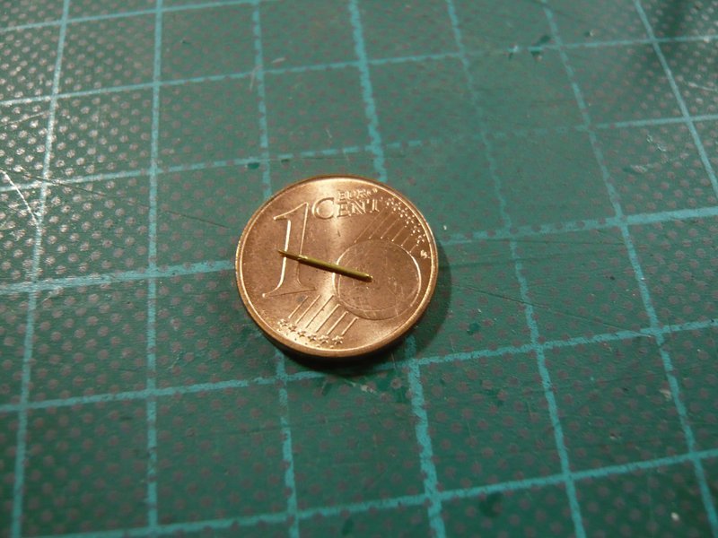
This couple one could now stuck into a 0,4 mm through-hole, but this effort is not worthwhile. ![]()
Therefore, I would be satisfied with a simple Styrene variant, whereto I have drilled out my dummy outlet,
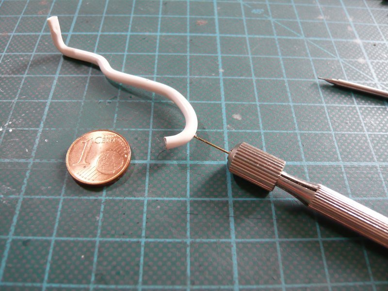
and glued a short stub Styrene rod (Ø 0,4 mm).
And this stub I’ve then reduced to approx. 0,4 mm in height. ![]()
And since this result seems perfectly adequate, I will probably stick with it. ![]()
![]()
5 Likes