Nice update… It is definitely a labour of love and it will be a nice reminder and tribute to those astronauts and the guy you knew/met.
Thanks John for your nice words,
and there are more memories every year and with every visit to the Kennedy Space Center (KSC). ![]()

So during my KSC Tour 2023 I met Wendy Lawrence in the Astronaut Encounter,

and last year Anna Fisher, Charlie Walker and Mike Baker, who all have found a place of honor along the stairway on my Wall of Fame on the way to my Filder Space Center (FSC). ![]()


And during my Return to KSC Tour 2025 in October, I will certainly meet more heroes of the Space Shuttle Program, whereupon I am already looking forward to and can hardly wait for it. ![]()
![]()
4 Likes
Hello everybody,
and let’s come back to the model world. ![]()
Finally the last two 18’’ outlets without rejuvenation also have received their support plates.
Then I have shortly pre-drilled the upper bows with Ø 0,5 mm, inserted rods (Ø 0,45 mm) for the nipples and glued them with MEK,
which then were cut and carefully sanded down to 0,4 mm height.
And then there were also still the six 18’’ outlets with rejuvenation which I had almost forgotten. ![]()
Therefore the same procedure all over again on these bows.
Now missing only the nipples of the two front 12’’ outlets, which previously still have to get their outlet openings with baffles. ![]()
![]()
5 Likes
You know, pretty soon you won’t have to visit Kennedy Space Center as your home will be well displayed museum in itself.
I wonder what’s Elizabeth is thinking while looking down. ![]()
What is happening to my beautiful home ![]()
3 Likes
Pipework looking great !! Was looking at those holiday snaps and the Saturn V ones … Interesting that Airfix are about to release that and a Space Shuttle soon.
Hi Mike,
memories are all well and good, but there is nothing like seeing the originals in person. ![]()
And Elisabeth sees everything from a heavenly perspective and shares my joy. ![]()
![]()
1 Like
Thanks John,
it’s always again an incredible experience. ![]()
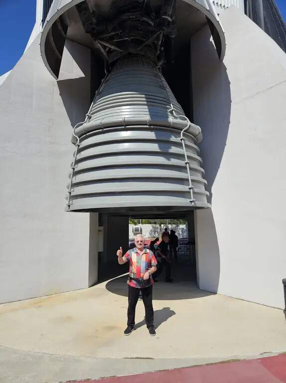
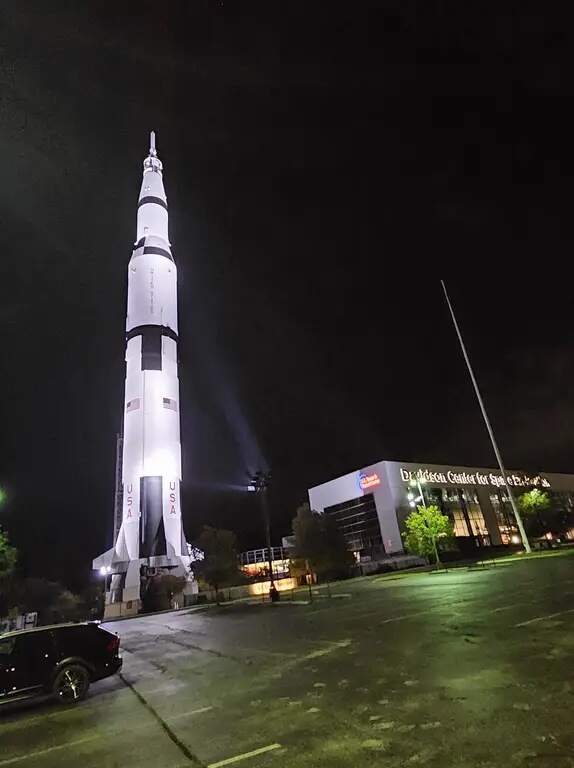
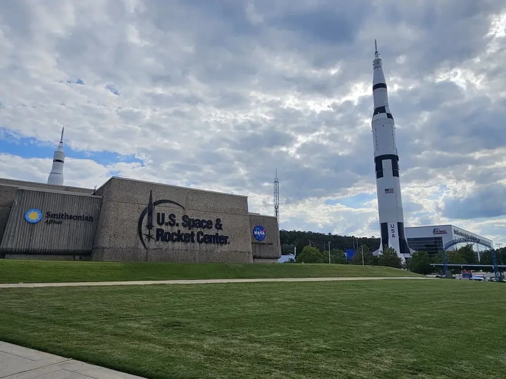
That’s why I flew to Huntsville, Alabama, last year. During in the KSC Visitor Center this moon rocket is only displayed lying flat in the Apollo Saturn V Hall, in the Rocket Garden of the U.S. Space & Rocket Center in Huntsville one can additionally admire the upright standing Saturn V, which overshadows everything else around it, with 111 m height, simply overwhelming. ![]()

Me under one of the five mighty F1 engines of the Saturn V. ![]()
Also the Pathfinder Shuttle Stack has been completely overhauled and has been shining in new splendor ever since again. ![]()

BTW, the two Airfix kits have been in my storage long ago. ![]()

That’s why my motto is: There are 24 hours in the day, and if that’s not enough, there’s additionally also the night. ![]()
Therefore my friend Brian Matney from Huntsville gave me the nickname, Manfred, the Midnight Modeler. ![]()
![]()
4 Likes
Some impressive photos showing those in all their glory … nice.
1 Like
Hello friends,
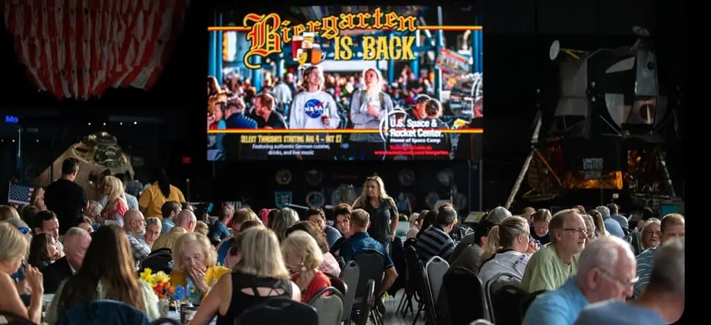
another unique feature of the Huntsville Rocket Center is of course the German Beer Garden, which takes place every Thursday in the fall in the Saturn V Hall under the Saturn V, where we had a great time together with my friends. ![]()
In Munich stands a Hofbräuhaus … ![]()


What a great event - Time to say Goodbye, even if It’s hard for me, but meanwhile I’m already planning my US Tour 2025. ![]()
![]()
2 Likes
Hi there,
today I want already times to have a look ahead how it goes on shortly. ![]()
There are still these two 9’’ outlets (Ø 1,4 mm), which branch off before the 12’’ outlets at the end from the 24’’ ring lines, then run through below the SRB Blast Shields,
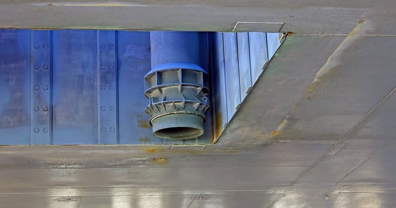
and feed the line with the outlet nozzles on the rear wall of the SSME exhaust chamber,
which I have completed for some time, as well as the tricky Firex line. 
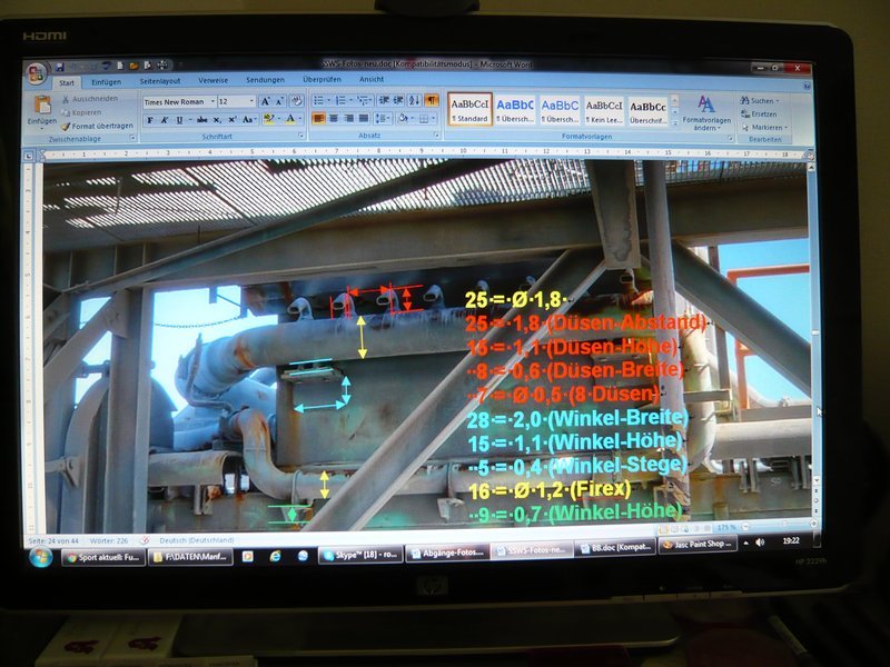
And at the other end of the 24’’ ring lines it goes on behind the TSM’s with the 16’’ rejuvenations (Ø 2,5 mm) which are tapering one more time to 11’’ (Ø 1,8 mm) after the first bending,
and end in the SSME chamber in these pipes stocked with eight tiny outlet nozzles. ![]()
In order to continue with these details, I had to make a lot of measurements and scalings again. ![]()
And as it looks like, it will be probably again pretty tricky, I guess. ![]()
![]()
3 Likes
Hello everybody,
here still a small addendum to two outlets that are missing yet, these are namely those four 6’’ outlets (Ø 1 mm) here, which although were to be seen already, but have not yet been regarded. ![]()
These transitions branch off from the ring lines, run under the SRB Blast Shields, and reappear between the front SRB Supports, whose ends with the outlet openings also already exist. ![]()
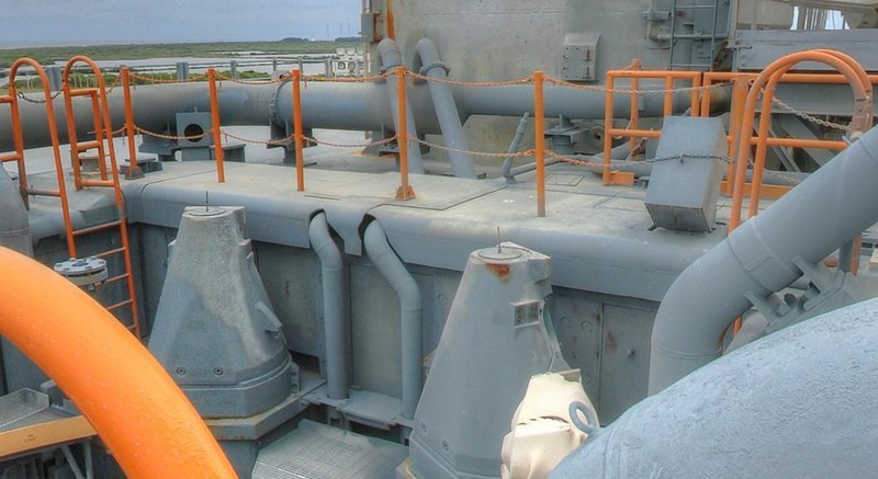
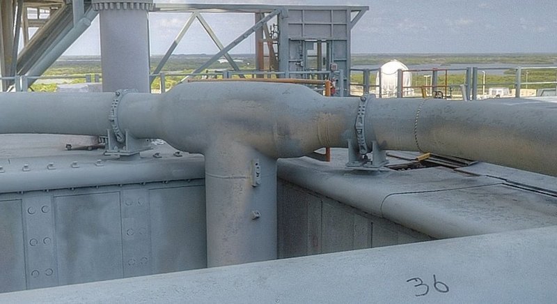
And the two 24’’ ring lines are fed in through these two 36’’ inlet pipes in the corners of the SRB-wells that were already shown also.
Here is the upper confluence into the ring line,
and here the lower end with the coupling elements,
which must not be missing. ![]()
And in order that during the further adaptation and assembly of various outlets everything goes well and the ring lines cannot shift constantly themselves, I have precautionally carved even more mounting aids.
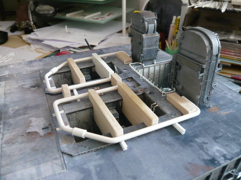
These mounting aids are then certainly also indispensable during subsequent assembly of so many pipe supports. ![]()
![]()
4 Likes
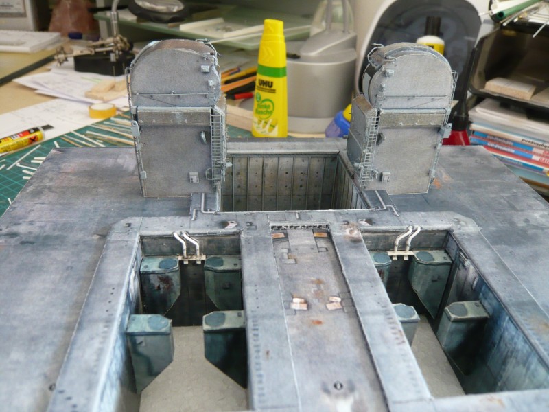
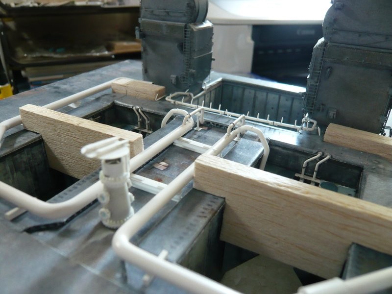
Hello everyone,
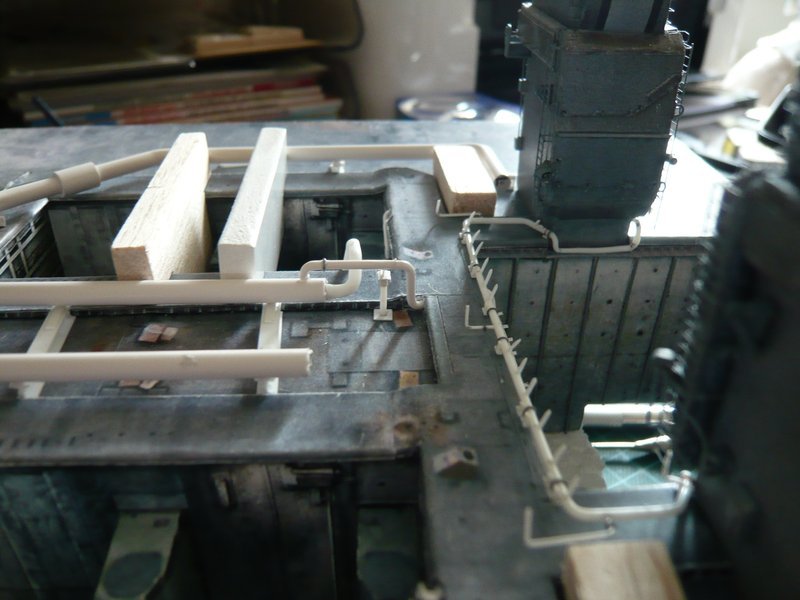
initially I still want to show the two 12’’ outlets, which now have got their outlet openings and baffles as well as the nipples. ![]()
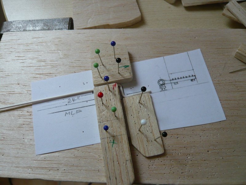
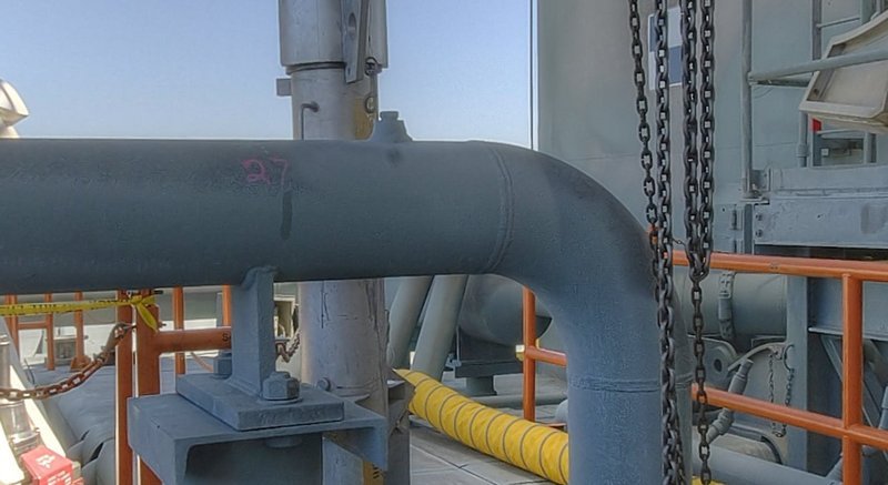
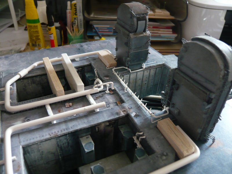
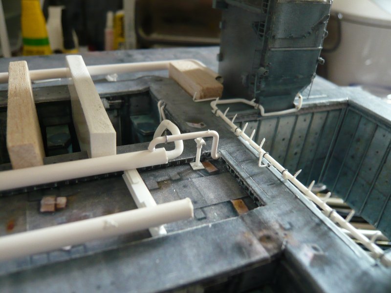
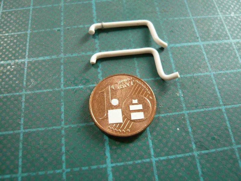
And after that it initially went on with the 9’’ transitions (Ø 1,4 mm) of the 24’’ ring lines (Ø 4 mm), standing on a tall support pillar.

What on the images firstly looks really practical and invites for scratching, then pretty shrinks on the 1:1 Sketch again. ![]()
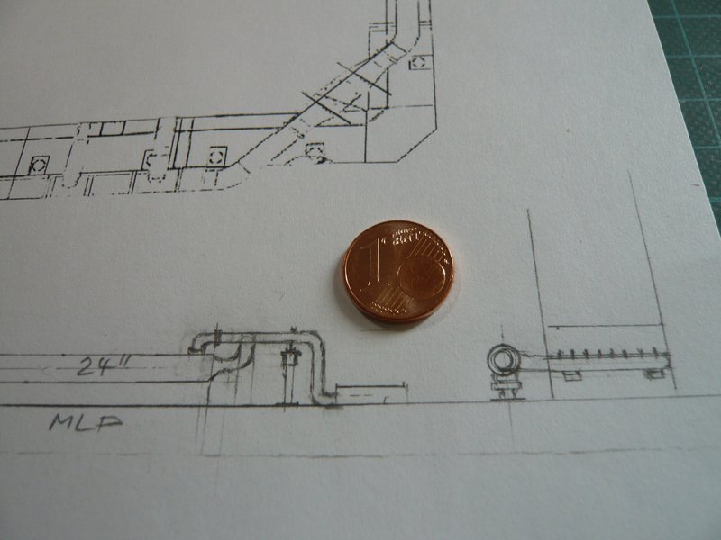
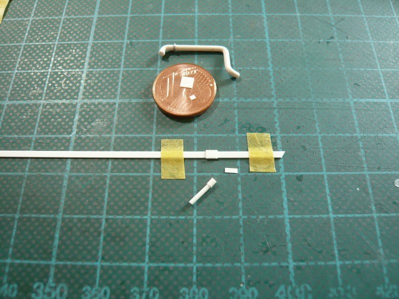
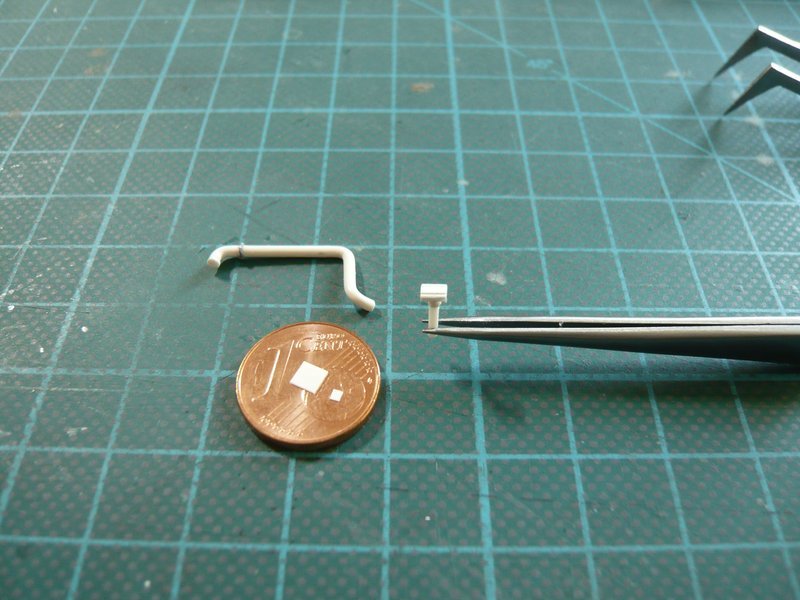
After determining of the dimensions of the components began the search for suitable profiles. For the pillar Evergreen rods are suitable with Ø 1 mm (bottom) and 1,4 mm for the upper sleeve, on which a flat 2 mm U profile sits and on this a small “Sickle”. Of the width for the U profile a corresponding Evergreen channel would be suitable, but is unfortunately too thick for this filigree support and the sides with 1 mm too high. ![]()
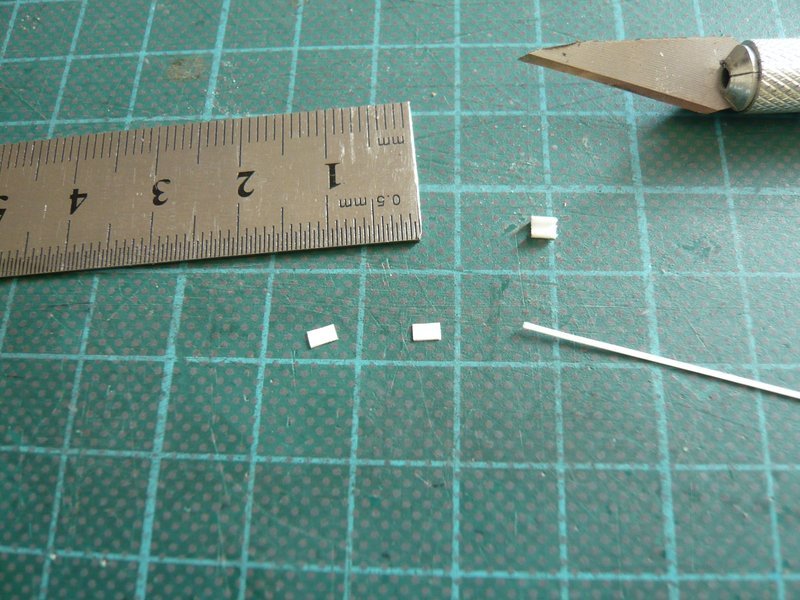
That’s why I preferred to bite the bullet and have scratched the profile of Styrene 0,15 mm. ![]() For the sides I have sanded down an Evergreen strip 0.25 mm x 0.5 mm to 0.15 mm and then glued with MEK.
For the sides I have sanded down an Evergreen strip 0.25 mm x 0.5 mm to 0.15 mm and then glued with MEK.
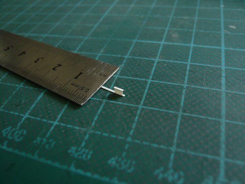
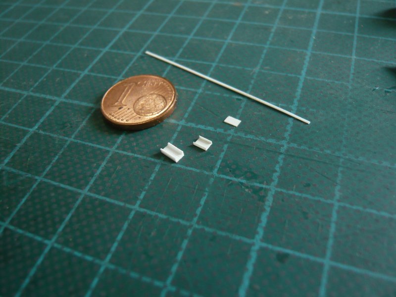
And the difference is clearly visible, as one can see here. ![]()
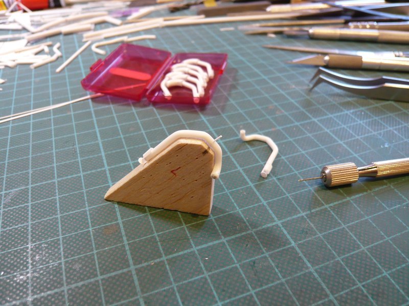
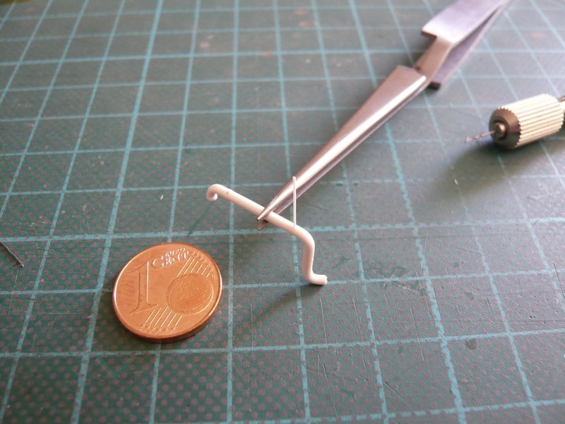
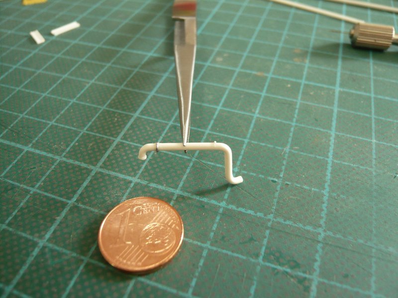
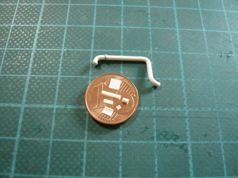
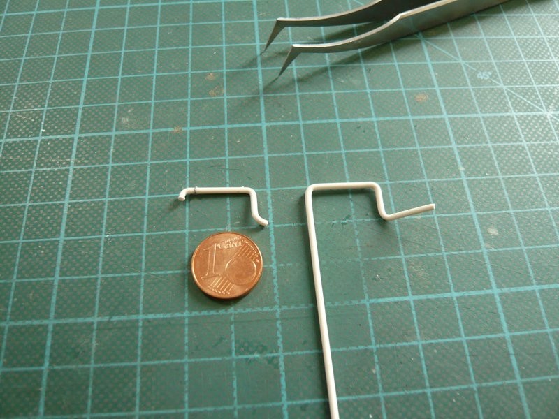
Then bending was indicated again, this time with the thin 1,4 mm rod,
what agrees very well with the sketch.
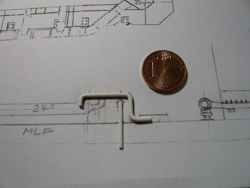
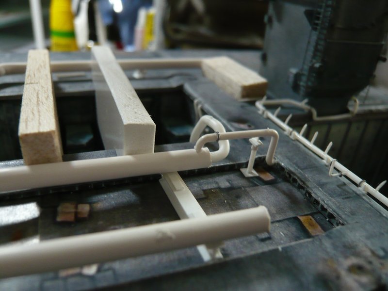
After that I’ve drilled a hole with 1,4 mm in the front inner corner of the SRB Blast Shields, and made a test that was okay instantly.
And that also fits well with the underlying 12’’ outlet. ![]()
Now is still missing the support pillar, which I’ll make tomorrow. ![]()
![]()
5 Likes
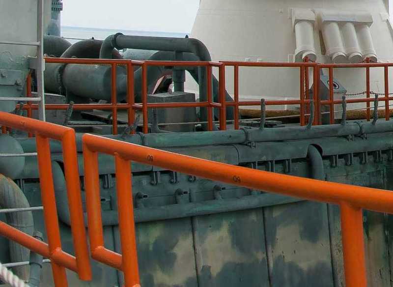
Really nice and impressive as always. Those orange railings will eventually give it a nice splash of colour as well.
1 Like
Thanks John,
sorry, my friend, regarding the orange railings I have to disappoint you. ![]()
Those railings will not exist on my crawler because they are only temporarily mounted, but I want to show the final countdown state before launch. ![]()
![]()
1 Like
Hello again,
but initially the 9’’ outlet still received a few small details. ![]()
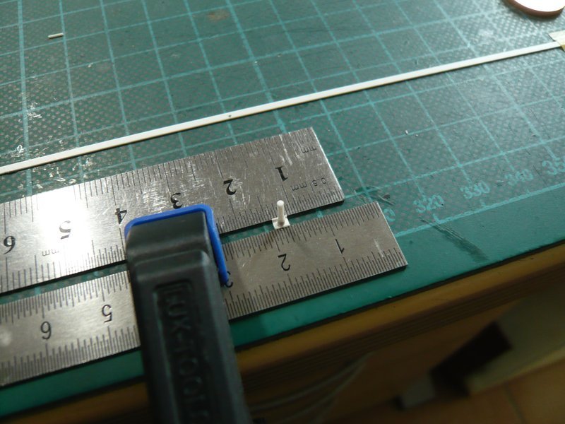
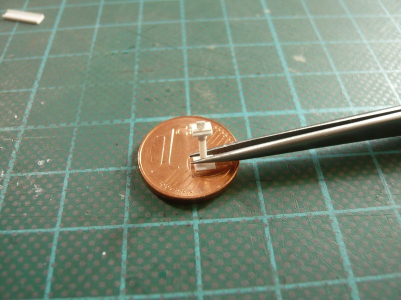
At the feed-point of the 24’’ ring line is a small thickening to see, for what I have punched a small Styrene disc (0,5 mm) with Ø 1,6 mm, which has already been glued, as can be seen in the following figure.
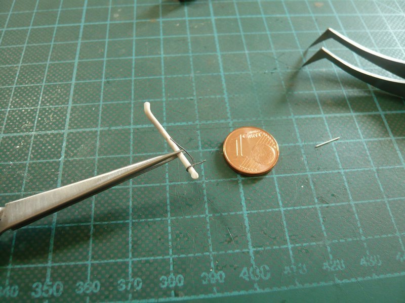
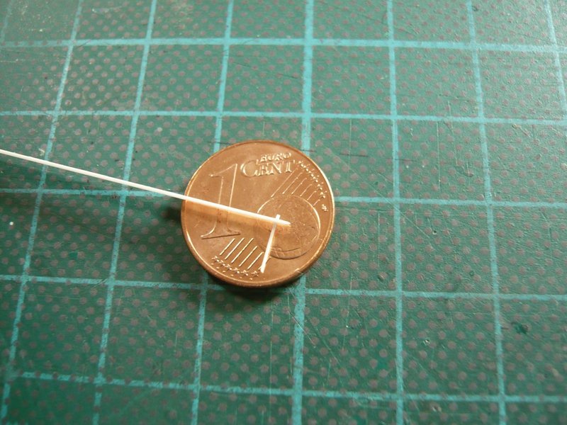
Due to the small diameter of the outlet of 1,4 mm also the diameter of the nipple is correspondingly smaller with only 0,3 mm, ![]() for what only a tiny hole were to drill,
for what only a tiny hole were to drill,
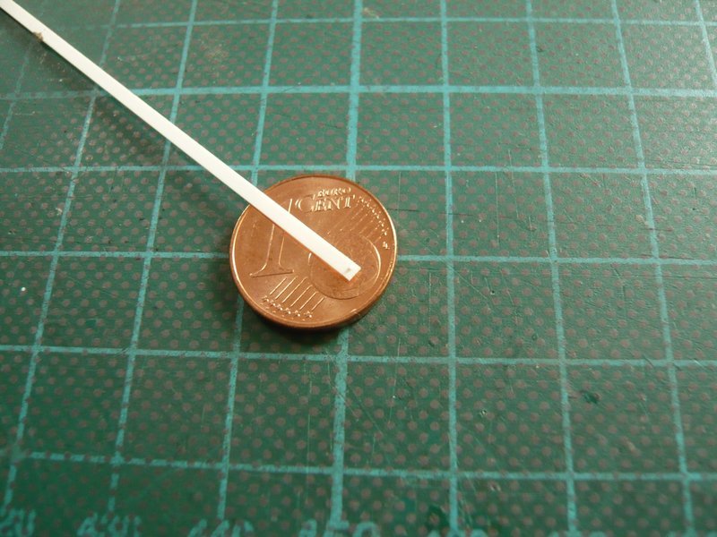
into which my thinnest rod with Ø 0,3 mm was glued. Next to it is a lead wire with a diameter of 0,3 mm, which I will use for the clamping ring on the other end.

The lead wire I have glued with CA.
And so the final outlet looks, from which I still need a second copy.
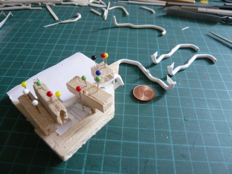
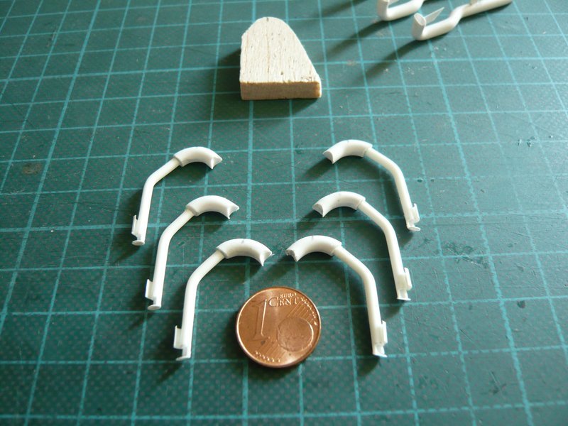
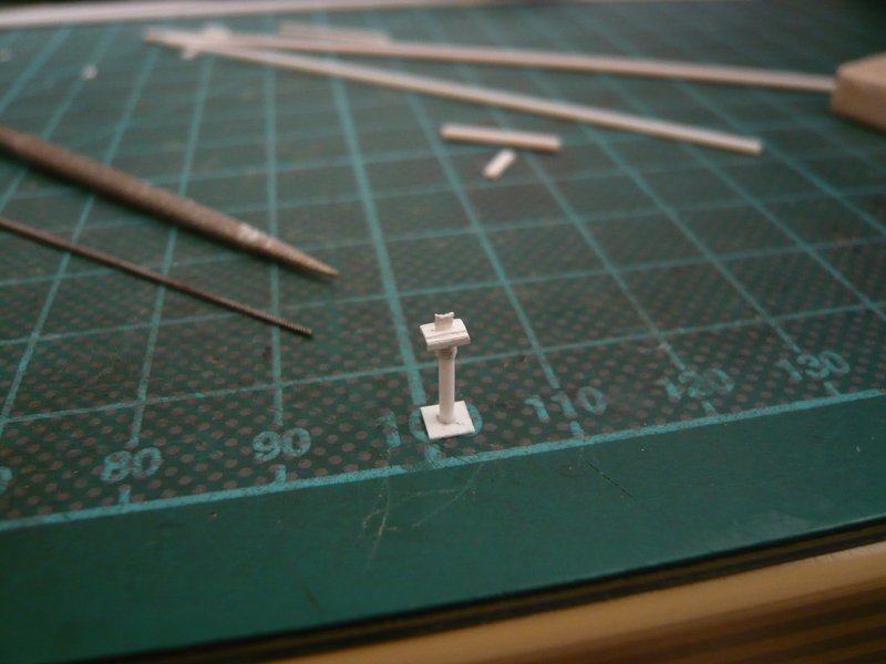
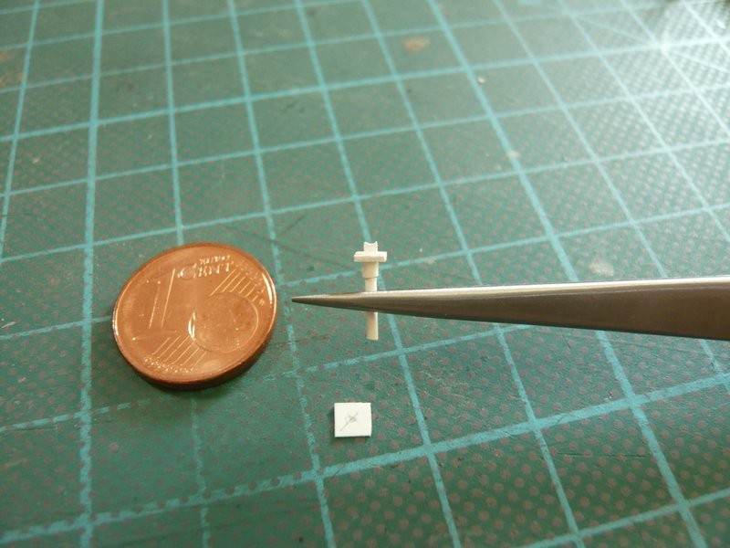
And now to the slender support pillar, which stands under this outlet and consists of six parts,
which I have already prepared and are all quite tiny,
which must be glued together now. ![]()
And I can tell you, the mounting should become a tricky matter due to the minimal contact surfaces. ![]()
Since I glued these things with normal Revell glue for possible corrections, one can not continue, but must wait until hardening. ![]()
And the height of the support I should also check from time to time, since it should not exceed 9 mm in order to fit even under the outlet.
And for that reason alone every now and then a break is necessary, like now, why the base plate and the top plate have to wait. ![]()
![]()
5 Likes
Hello everybody,
if you are still interested, here is the next update. ![]()
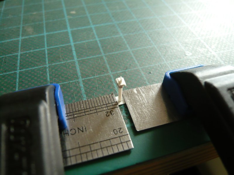
Since I still wanted to check the total height of the support pillar, I have not initially sanded the tiny rounding in the upper pipe holder, especially since it is anyway only 1 mm x 1 mm “big”. ![]()
The problem with this prototype is, that the height of the components should be exact as possible on the tenth of a millimeter, if in the end should be reached the calculated required total height of 9 mm, so that the support fits under the transition. ![]()
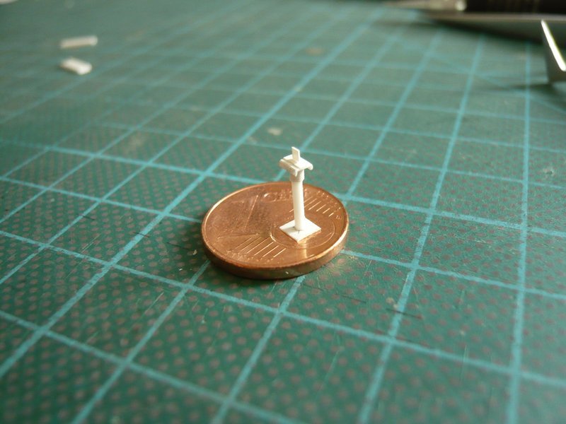
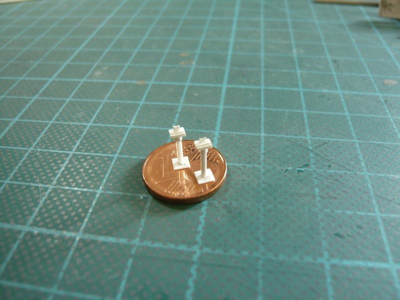
Subsequently, the support was positioned on the base plate and glued,
and then vertically aligned on all sides vertically.
And so the filigree structure looks, which is very fragile and wherefore the further handling is to enjoy with caution.
With the optical look of the support I am already very satisfied, although actually still missing these two screwings, ![]()
which I wanted to try at least times. In my estimation, one could scratch it by thin rods, which would, however, which would be again in the boundary region of the nipples with Ø 0,3 mm. ![]()
That would be even doable, although this strip (0,37 mm x 1,5 mm) is slightly wider than the only 1 mm wide plate under the pipe holder,
and through the shadows it could be seen even better in the painted state, questionable would be, however, from what distance … ![]()
But more important is the question whether and how the support would fit at all. ![]()
And to my surprise, it fits already together relatively well,
although the left side of the pipe hangs a bit in the air, as can be seen more clearly in this close-up.
But that should be able to be balanced if I sand even a tinier rounding in the tiny pipe holder (1 mm x 1 mm) and it plays along. ![]()
Although this support was quite tricky, this looks but overall very well. ![]()
![]()
6 Likes
Fair point … I did actually wonder if they may have been temp after I wrote that post … It will still look just as amazing though …railings or not ![]()
1 Like
OMG John, I still have more than enough details to scratch. ![]()
![]()
1 Like
Hi there,
making of the tiny rounding was not a problem, especially since only a hint of 0,15 mm was necessary. ![]()
And here is the result,
and because the transition now sits a little bit lower, so far everything is okay. ![]()
Therefore, the rounding of the second pipe holder will be made before assembly.
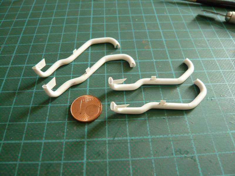
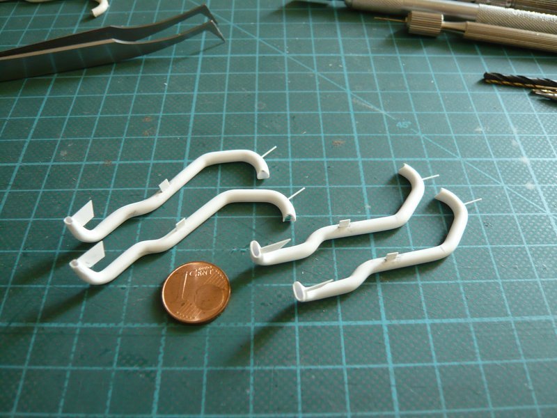
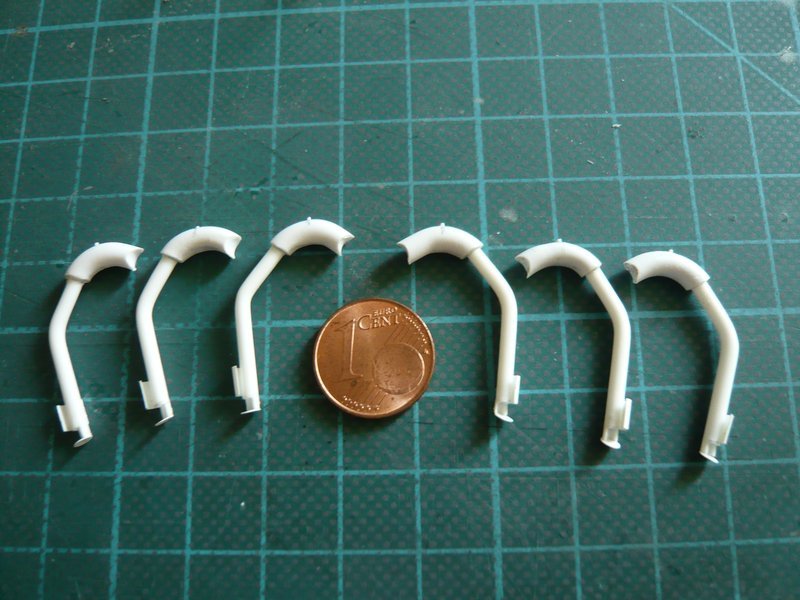
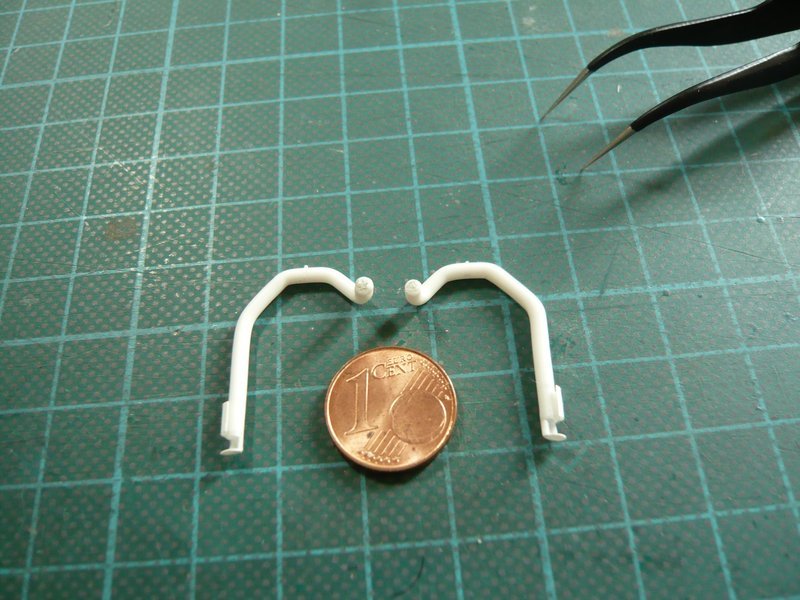
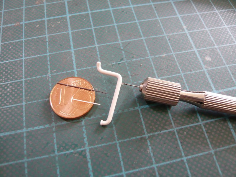
Now it was the turn of the second 9’’ transition, which first had to be bent again.
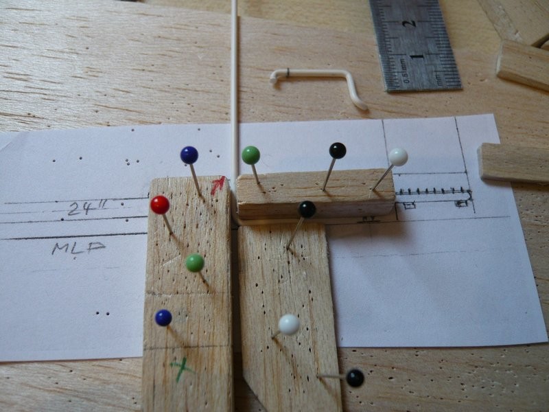
Although the processes are now already familiar, the difficulty lies in getting the transitions as identical as possible. ![]()
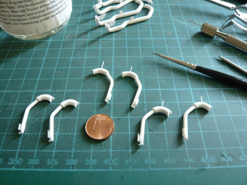
These are the individual parts for it, apart from the two rods for the support.
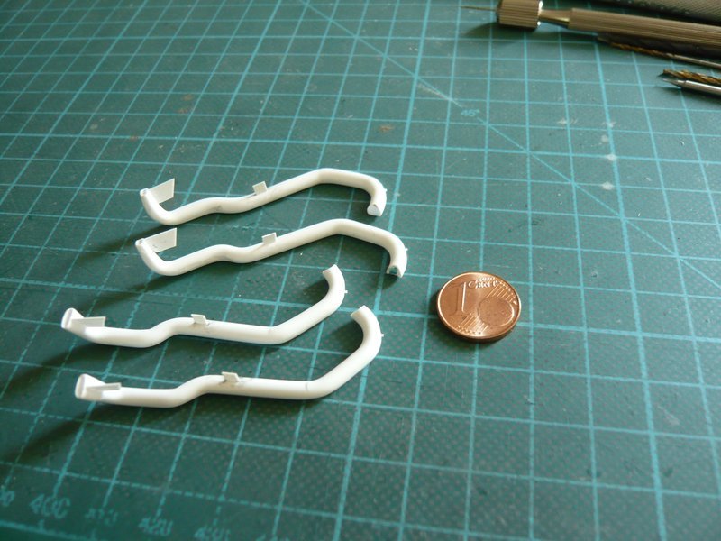
After the filigree U-shaped substructure was scratched, it was time for the difficult assembly of the parts, which was again quite stressful. ![]()
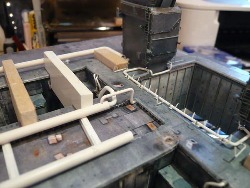
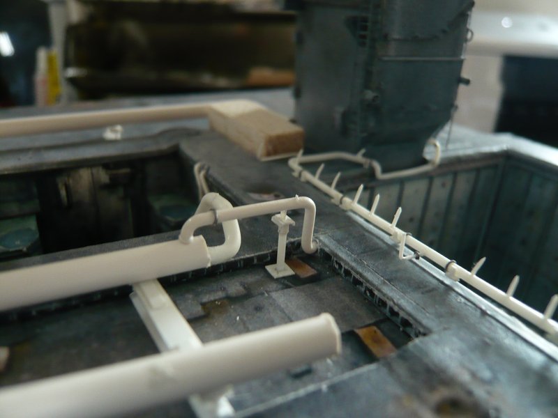
And with that the couple was complete, ![]()
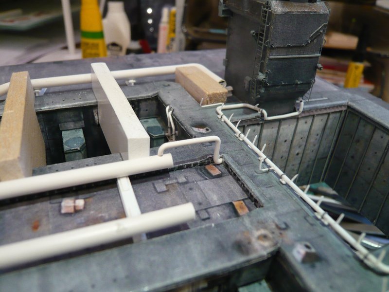
and could be tried on on the MLP.
Although the provisional attachment of the outlets with Pattex is also a tiresome game of patience and does not last long, ![]()
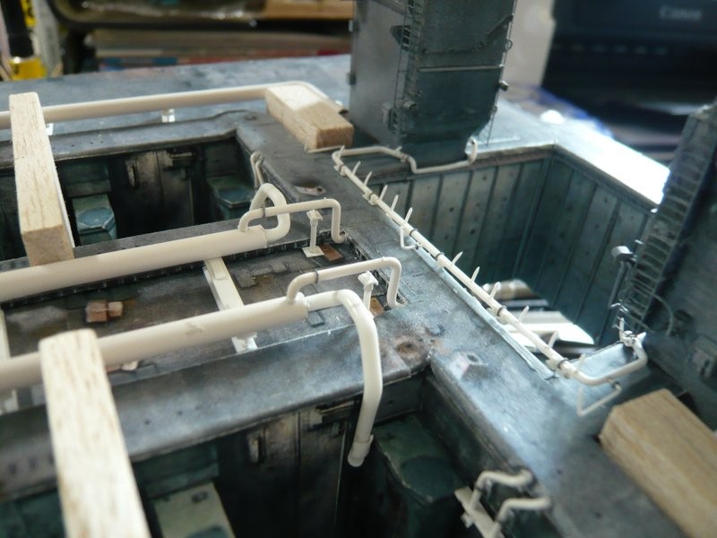
the impressive overall impression is worth the effort, which is why I brought back the Rainbirds again. ![]()
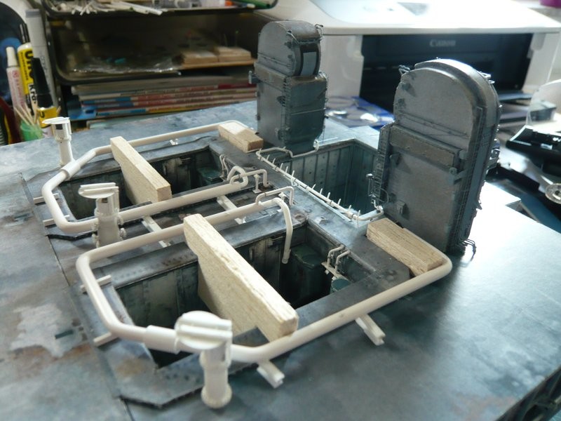
That’s it for today. ![]()
![]()
6 Likes
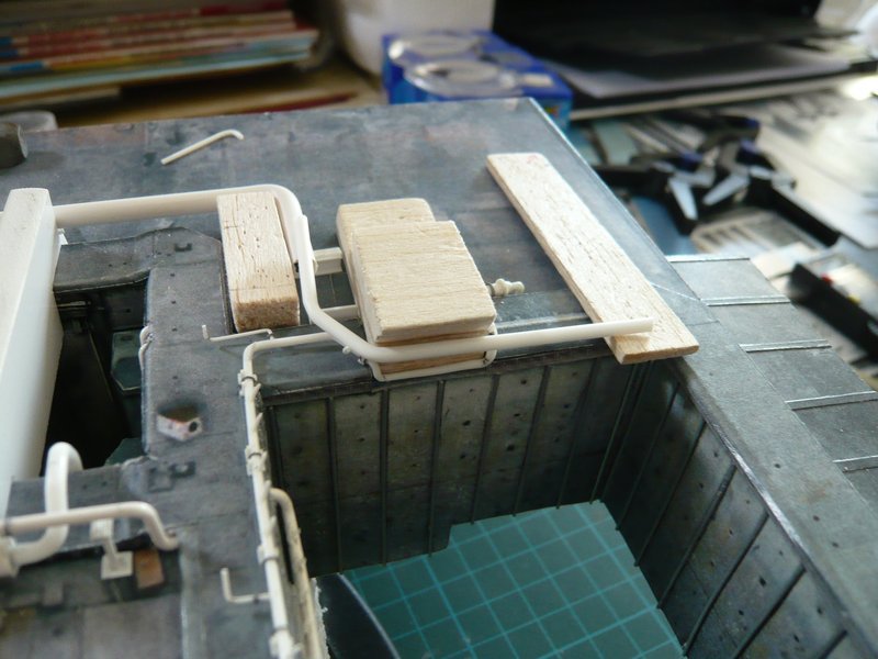
Hello everybody,
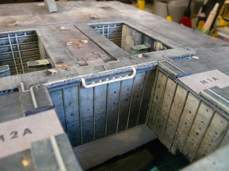
meanwhile shape and seat of the nozzle pipe have been slightly modified, and for facilitating the tests I have tinkered a little TSM Balsa dummy to avoid unnecessary stress for the final TSM. ![]()
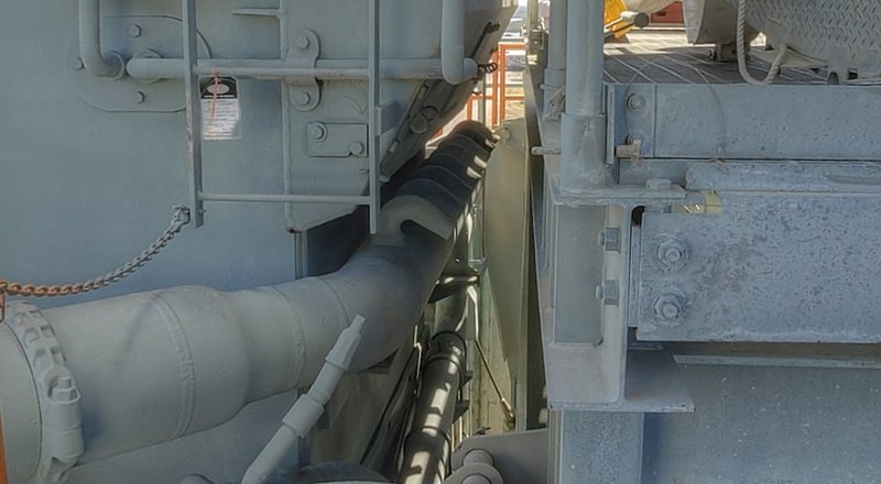
And hence to the tricky nozzles that had already made some headache a year ago dealing with the nozzle pipe on the rear wall of the SSME chamber. ![]()
Because my former manufacturing method of the individual nozzles in retrospect appeared as being too complicated, I have fiddled about another solution that should be less stressful. ![]()
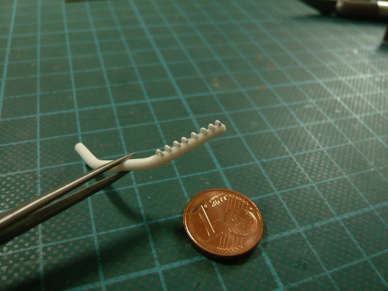
While on the former almost twice as long tube (approx. 32 mm) were arranged six nozzles, on this tube (about 16 mm) under the TSM this time even eight nozzles with Ø 0,5 mm are to be accommodated, resulting in distances of about 1,4 mm. ![]()
For the marking and drilling I have benefited of a PE template (cmkkits.com) for 0,8 mm rivets, which was very helpful. ![]()
First I have pre-drilled with Ø 0,3 mm and then after that with Ø 0,5 mm.
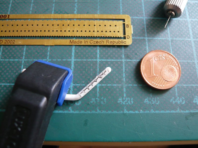
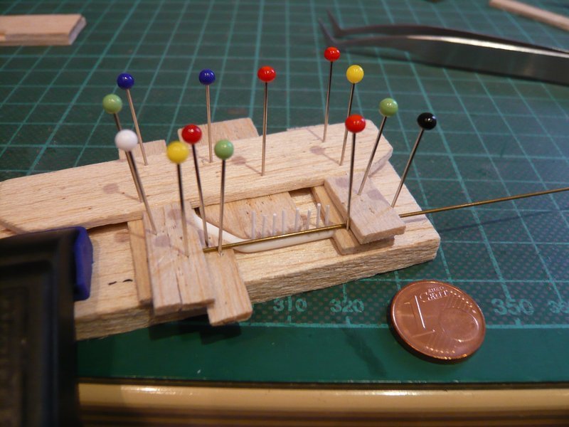
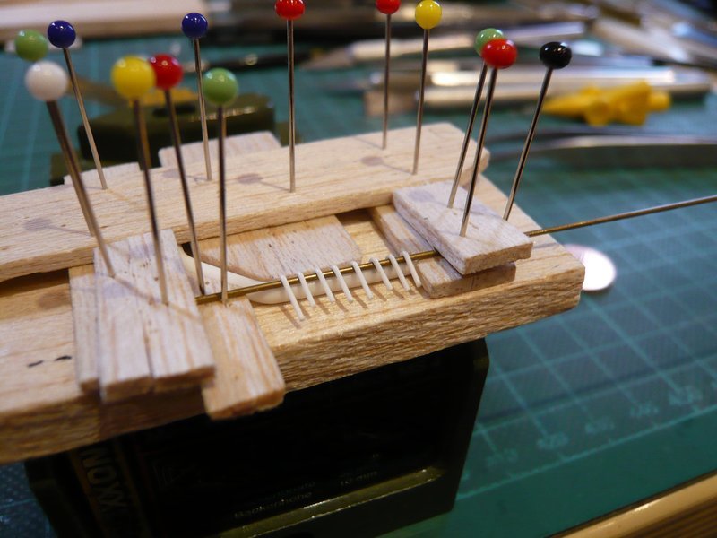
The idea was to insert somewhat longer rods (about 7 mm, Ø 0.5 mm) into the holes, to glue them with EMK and thereafter to bend all together at one time under moderate hot air in the final form, and then to cut. ![]()
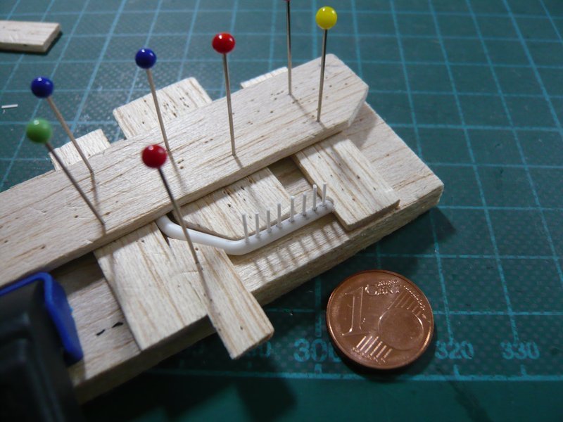
Therefore, the pipe had to be clamped again in a smart Balsa corset, what has proven itself in similar form already several times. ![]()
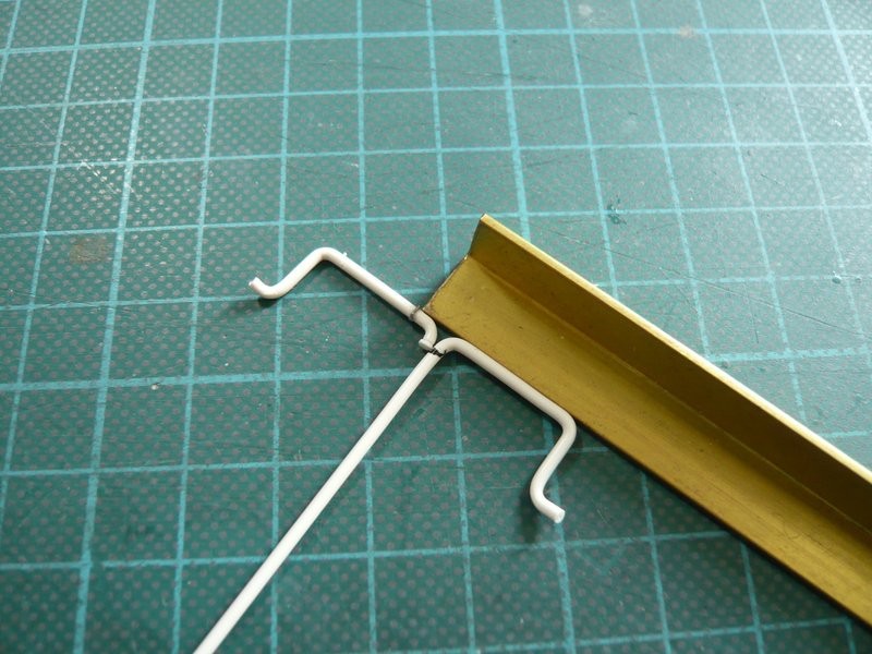
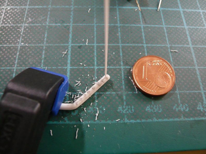
The required clear height of the nozzle bows results from this close-up on the basis of the reference diameter of the nozzle tube (Ø 2,0 mm) to about 0,6 mm,
which is why I now have clamped a corresponding brass rod with Ø 0,6 mm directly behind the nozzle rods.
And now the entire row could be bent, the Proxxon Gun in the right hand, and with Left the rods were carefully bent down with the Balsa slat,
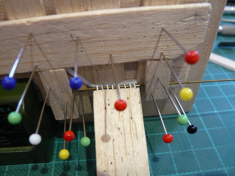
what has worked well straight away. ![]()
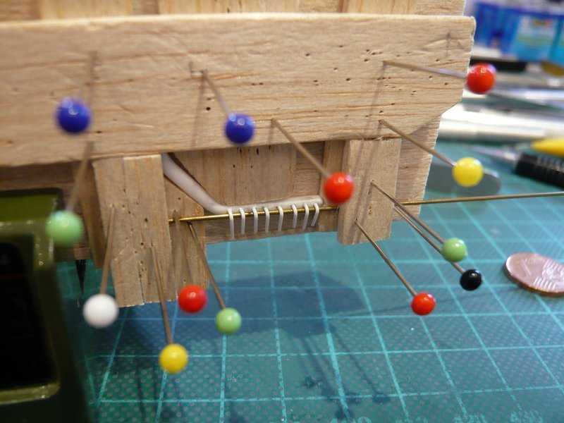
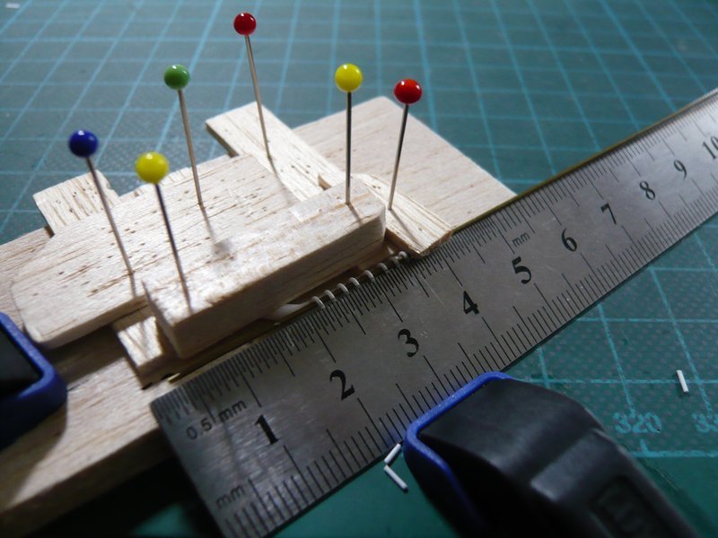
After the nozzle lengths were marked,
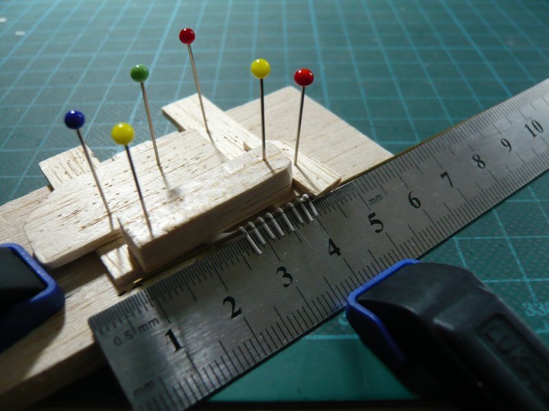
they were cut off on the steel ruler with the cutter chisel.
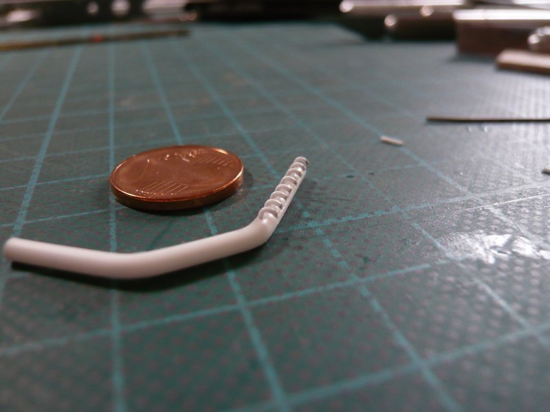
And then it looks like this. ![]()
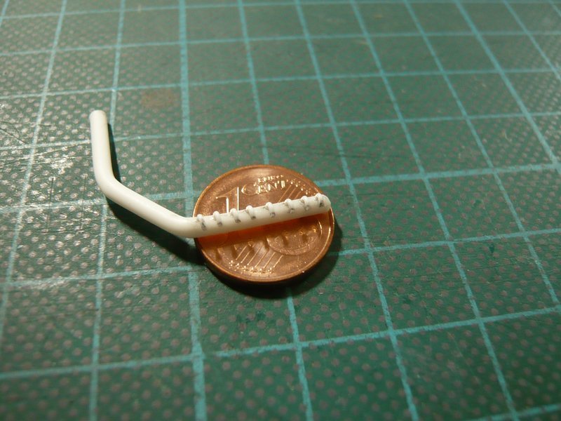
And from this result, I am now surprised, because this was not necessarily to be expected. ![]()
Now I can calmy turn to the nozzle openings, which can tolerate a little bit Tuning.
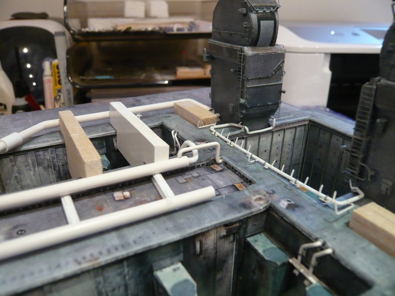
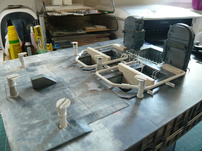
And here are two images of today’s try-on on the MLP. ![]()
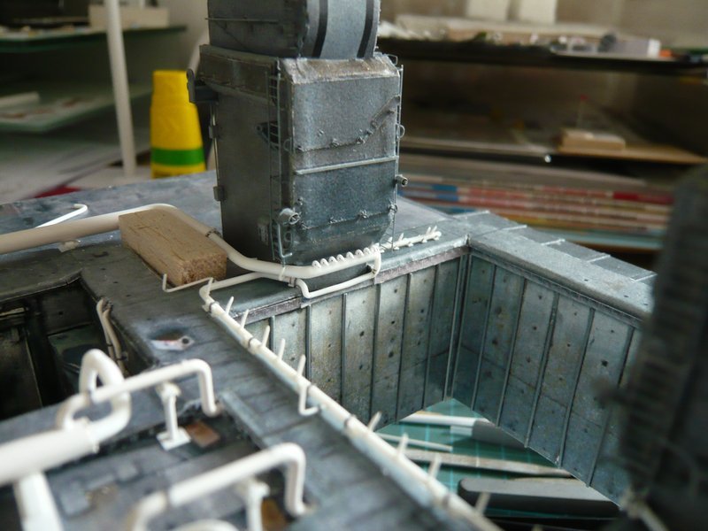
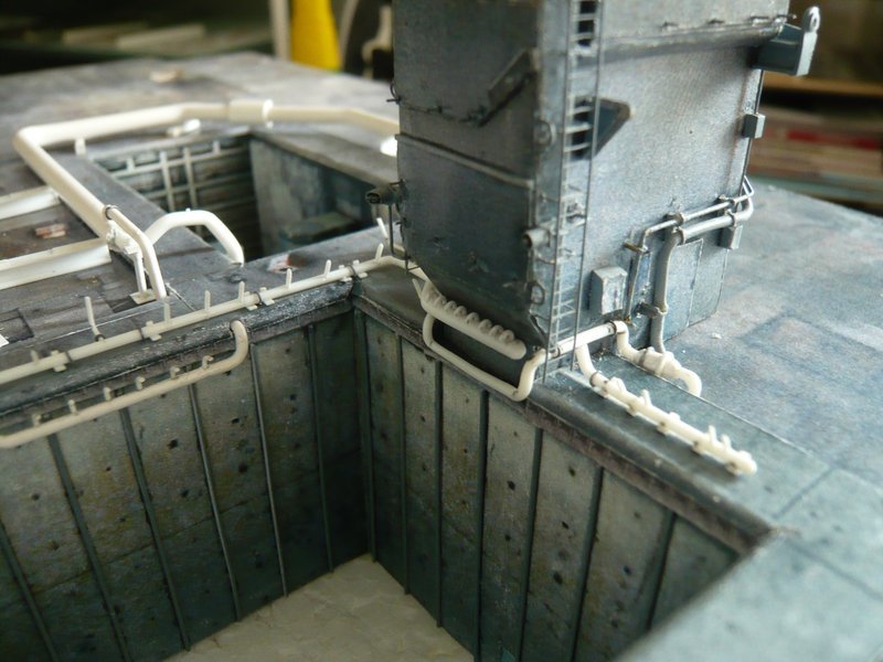
This is all still pretty shaky, but otherwise fits quite well. ![]()
![]()
8 Likes