Superb work as ever ![]()
1 Like
Thanks John and Hi folks,
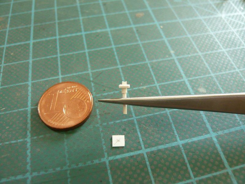
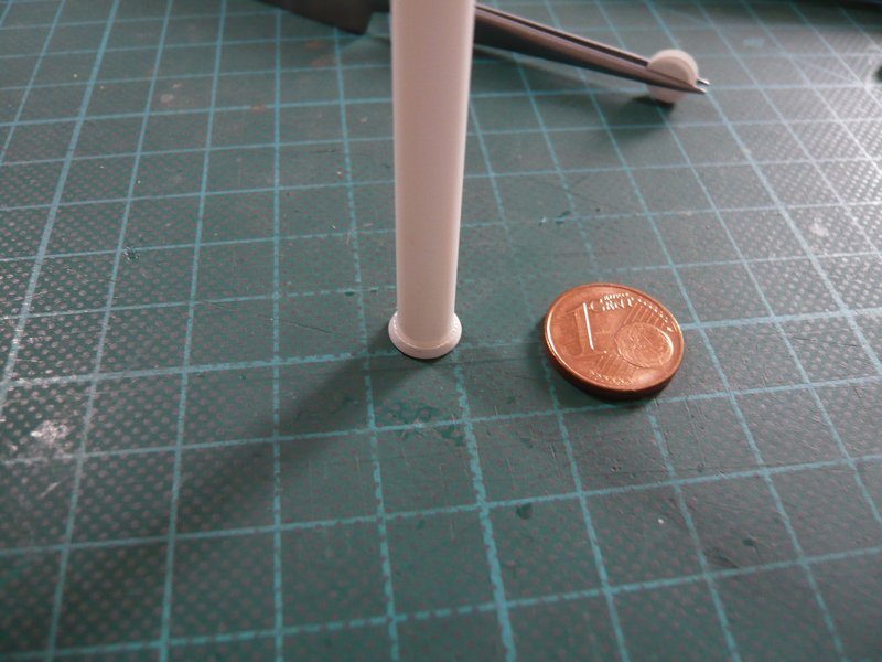
today, the second 9’’ transition was scratched, which had to be bent again initially. ![]()
Although the processes are now already familiar, the difficulty is to make the transitions as identical as possible. ![]()
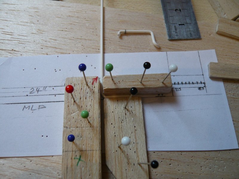
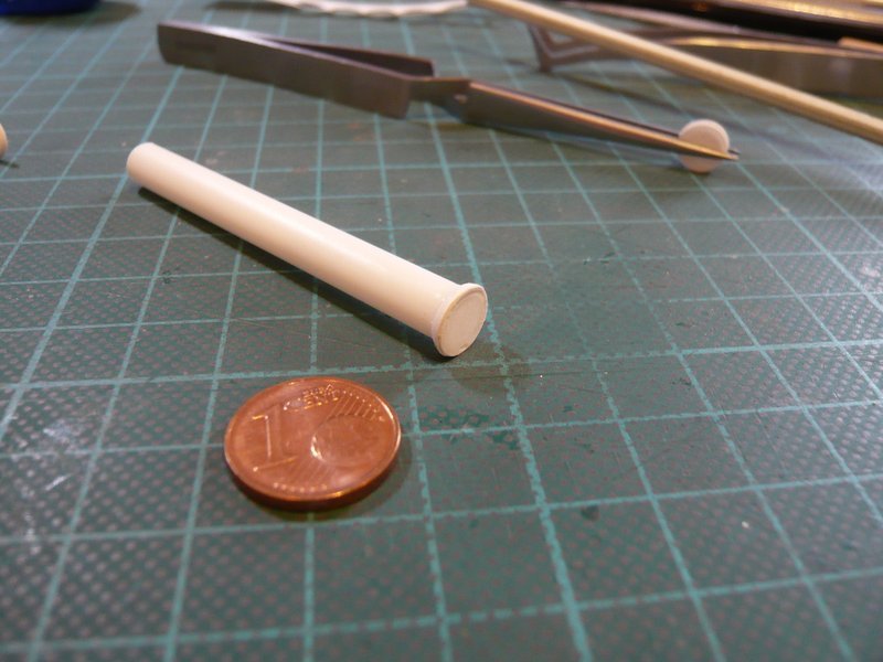
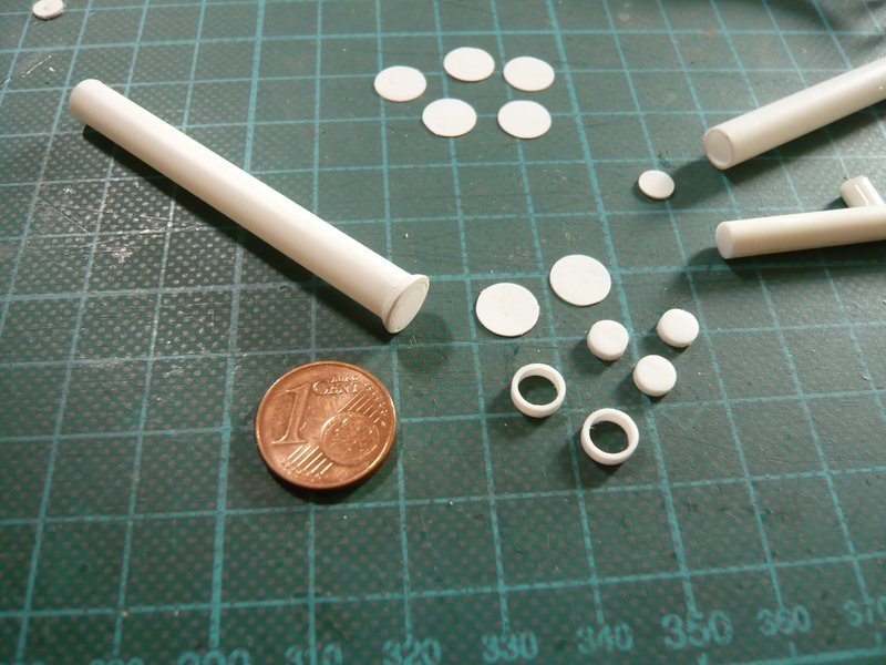
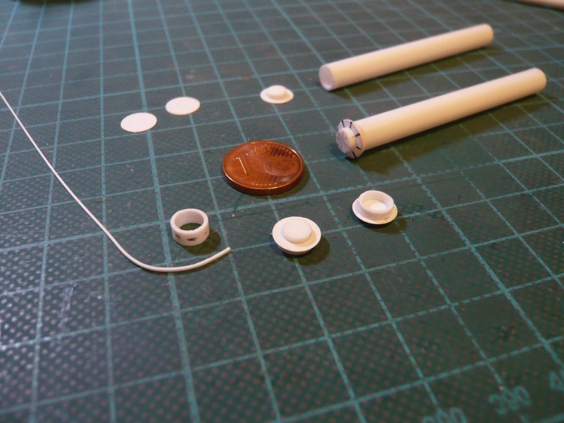
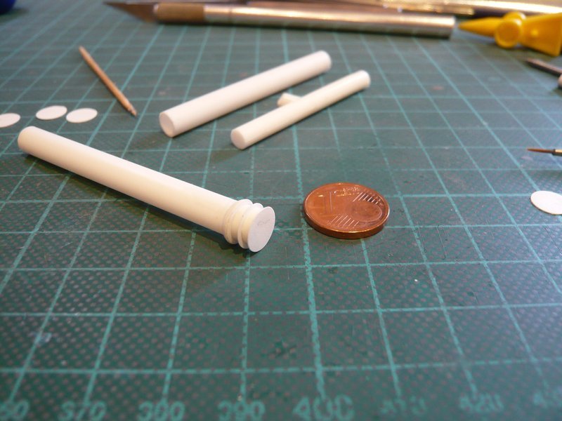
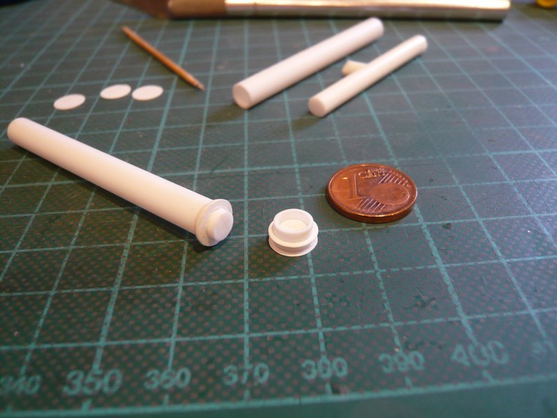
These are the individual parts up to the two rods for support pillar.
After the filigree U-shaped substructure has been scratched, the difficile assembly of the parts followed, which was quite stressful again. ![]()
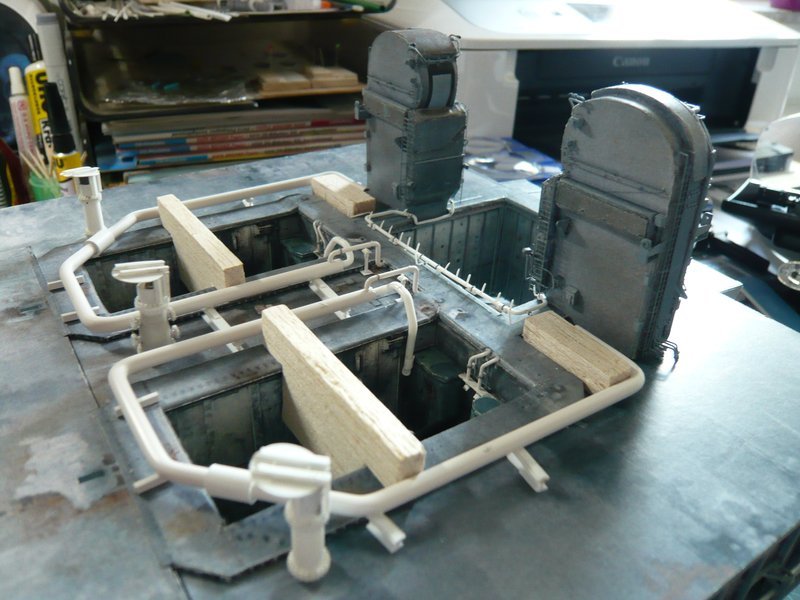
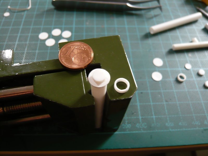
And so the couple was complete, ![]()
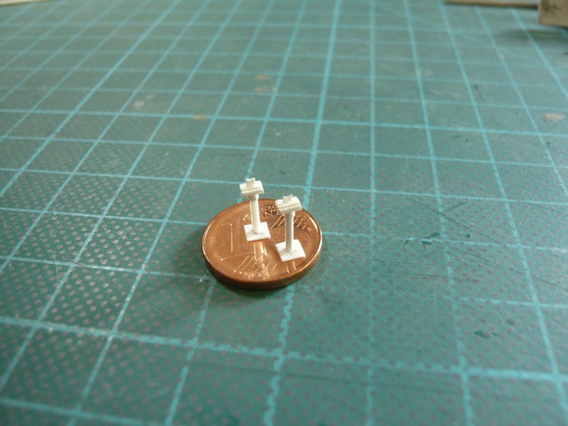
and could be tested on the MLP. ![]()
![]()
5 Likes
Hello friends,
although the provisional fastening of the outlets with Pattex is also such a tiresome game of patience and does not long hold out, ![]()
for the imposing overall impression the effort is worth to me, which is why I have brought out the Rainbirds again. ![]()
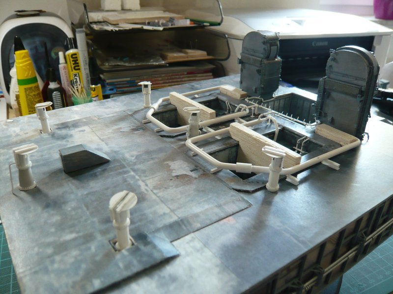
So much for today. ![]()
![]()
5 Likes
Hello everyone,
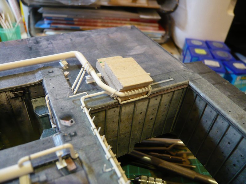
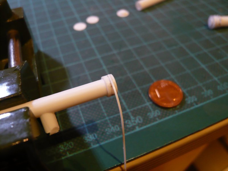
meanwhile it went on with the other nozzle tube under the LH2 TSM. ![]()
At first it was drilled again,
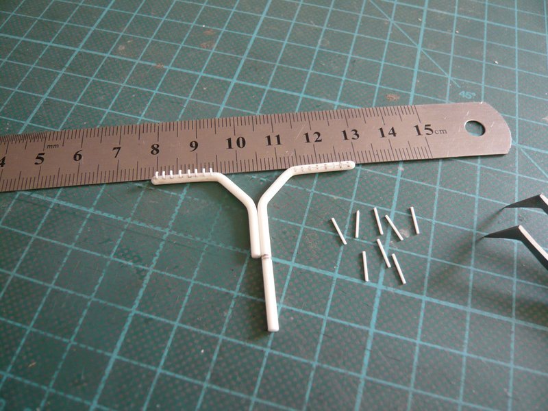
then the 0,5 mm rods for the nozzles were inserted and glued with MEK.
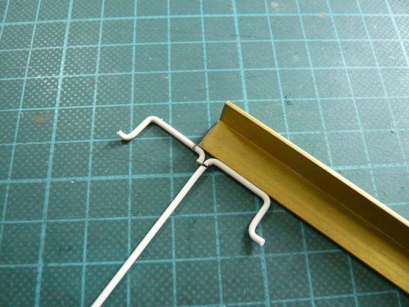
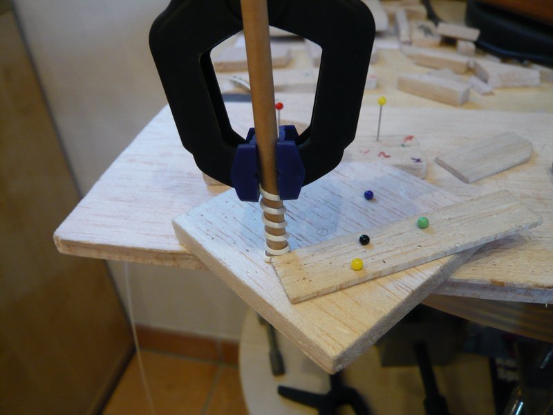
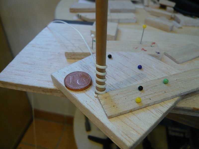
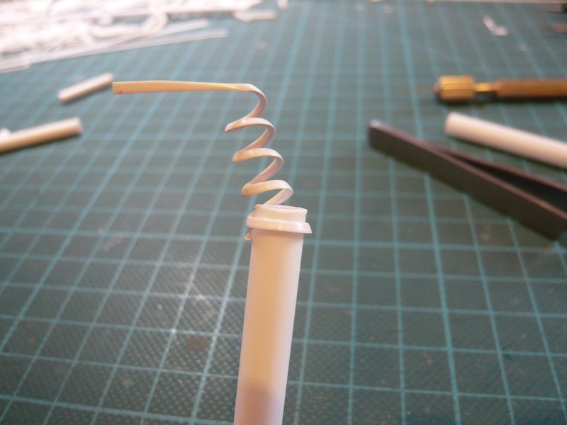
Then again followed my standard clamp procedure for the bending process with inlaid brass rod.
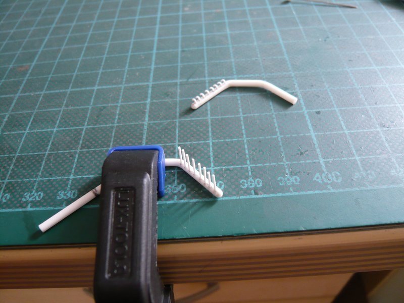
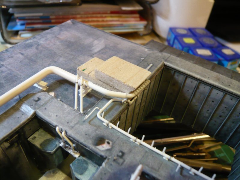
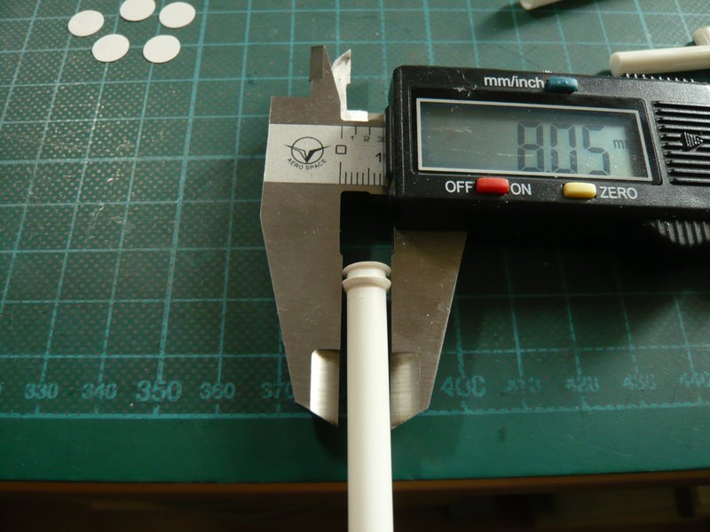
The bending was followed by the reduction of the overhangs, wherefore the already finished nozzle tube was very helpful for measurements and therefore was clamped next to it. ![]()
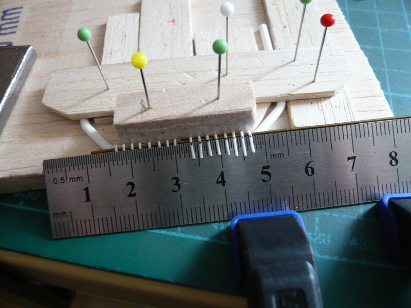
Then the overhangs were separated on the steel ruler.
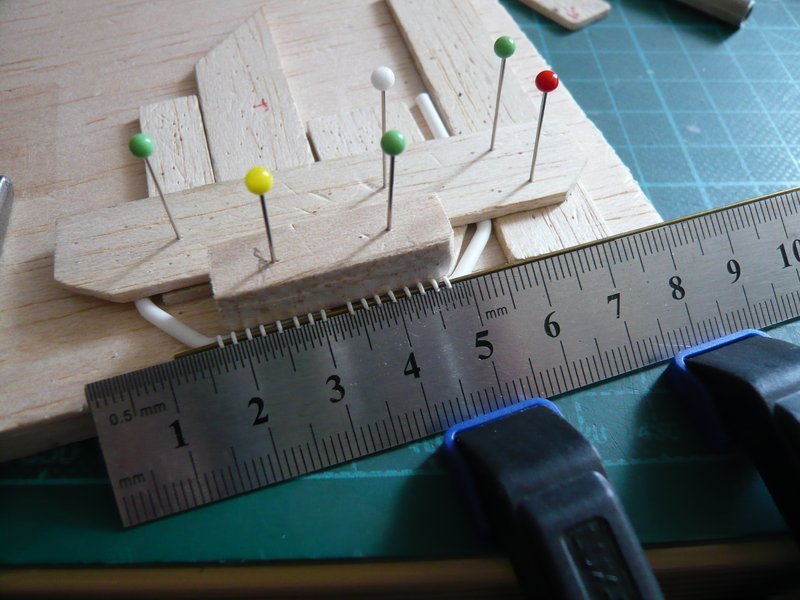
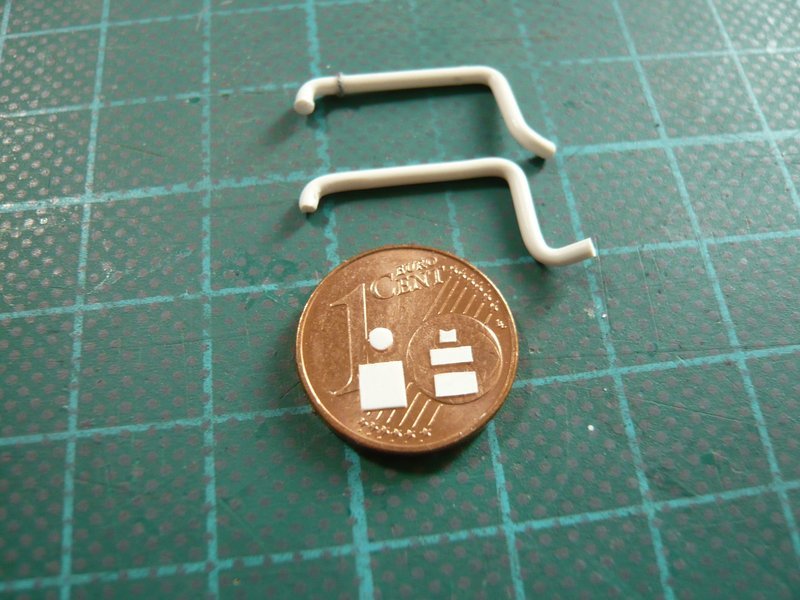
And these are the two nozzle tubes, left for the LOX TSM and right the new for the LH2 TSM, except for the mirroring almost identical twins. ![]()

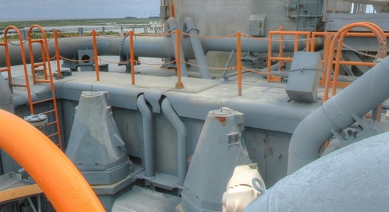
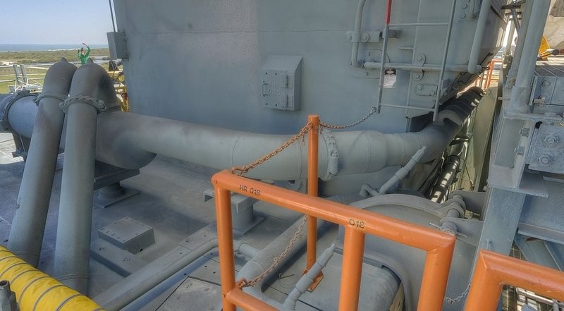
And so it went on the fly to the 6’’ outlets which run behind the two TSM’s from the ring line, then under the SRB Blast Shields,
and end on the back walls of the SRB chambers.
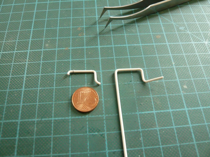
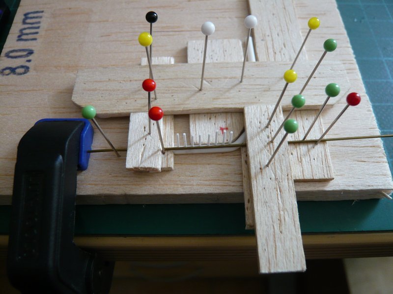
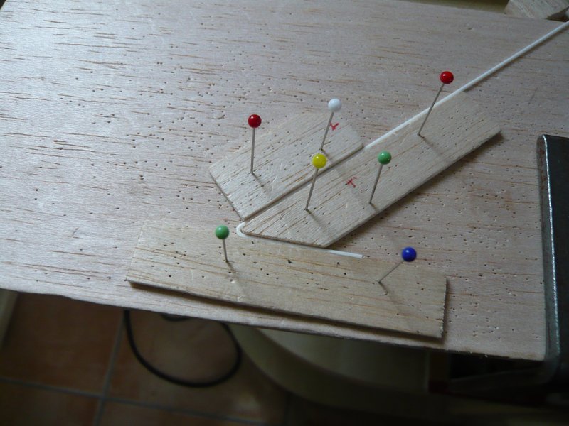
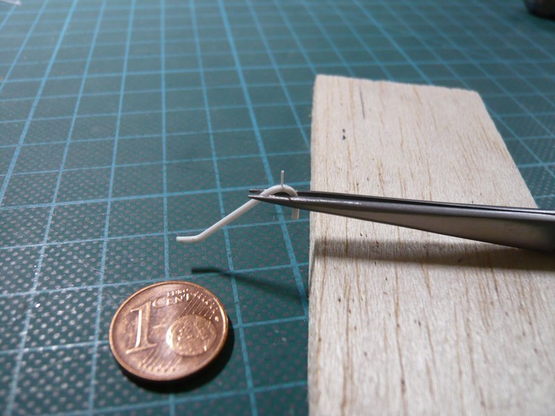
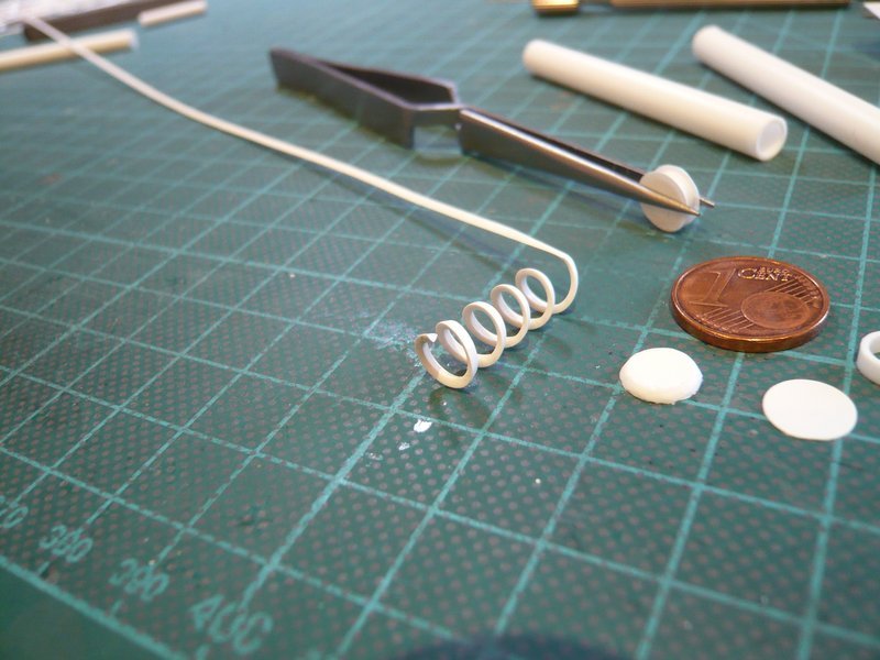
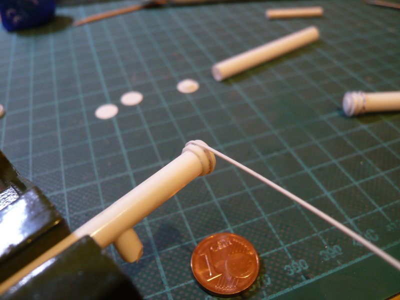
After the required dimensions were determined, then followed the bending of the rods (Ø 1,0 mm) around a corresponding template, which is by now become routine. ![]()
Now the appropriate length of the inclined portion only had to be found which one can measure unfortunately nowhere directly due to the oblique arrangement, not even from my little sketch of the true to scale side view. ![]()
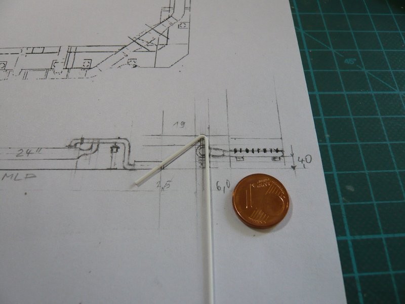
So only remained Trial & Error with slightly oversize, ![]() what then looks so.
what then looks so.
Although the bow is indeed a little too wide and should become a bit narrower,
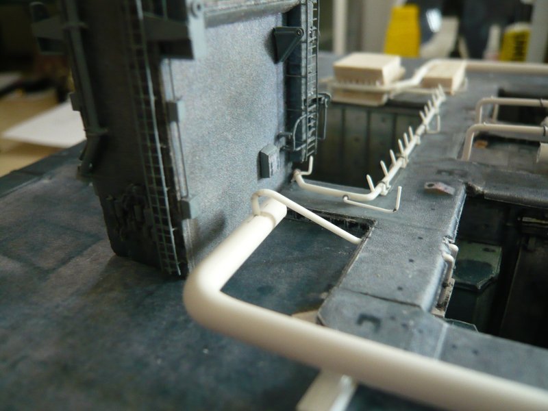
but from the arrangement it fits already quite good.
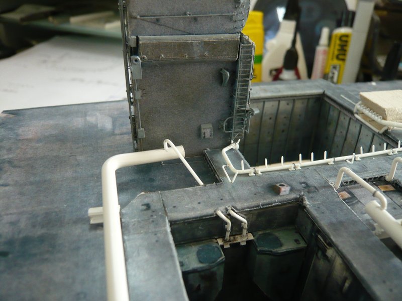
And the test fitting of the new nozzle tube right in the picture around the TSM dummy is also okay. ![]()
That’s it for today, tomorrow is another day. ![]()
![]()
5 Likes
Hello everybody,
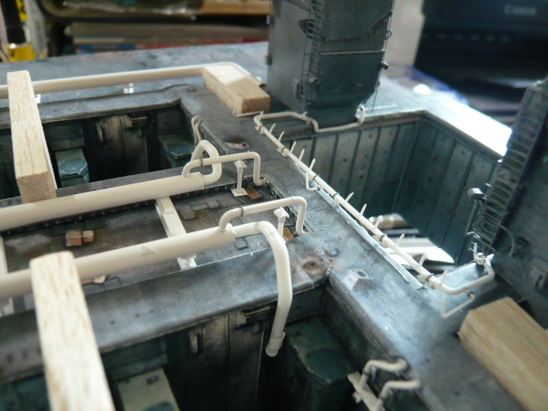
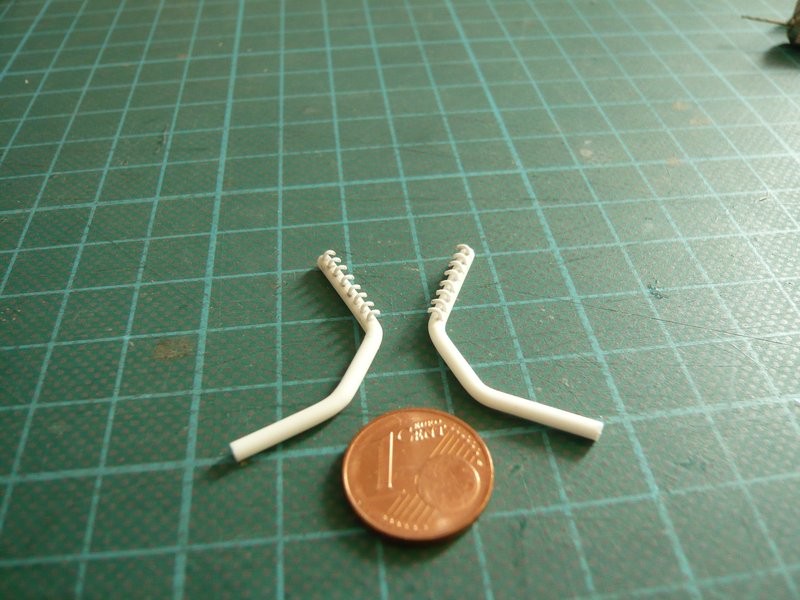
today also the second 6’’ outlet of the couple has been added, and the other two outlets for the right side I have also still bent. For the clamping rings I have wrapped lead wire Ø 0,3 mm around a 1 mm rod and then cut with a razor blade. ![]()
And even on these thin pipes there are the already known nipples, for which I will use Styrene rods with approx. Ø 0,2 mm. ![]()
And here the pipes have been “welded” to the ring line and threaded under the Blast Shield. ![]()
This fits in so far as quite well into the picture,
now I have to fit in only the correct adapter pipe with the rejuvenation on 12’’ (Ø 2,5 mm) at the end of the 24’’ ring line (Ø 4,0 mm) and to cut the nozzle tube (Ø 2,0 mm) just behind the TSM corner, then the strand is finally complete. ![]()
And how could it be otherwise, these rejuvenations stand on a short support, which is constructed similar to the two pillars under the 9’’ transitions at the other end of the ring lines, and therefore they are also on the to-do list. ![]()
![]()
6 Likes
Hello everybody,
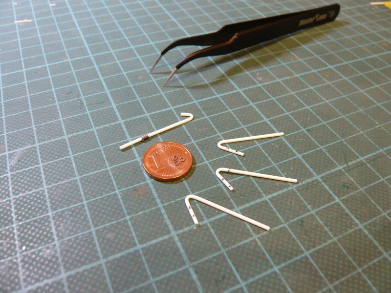
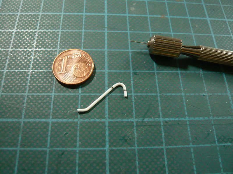
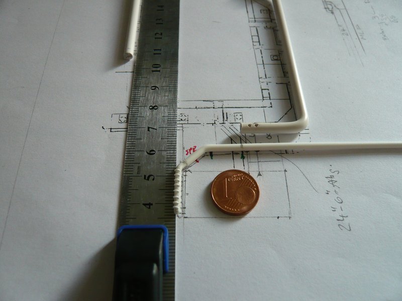
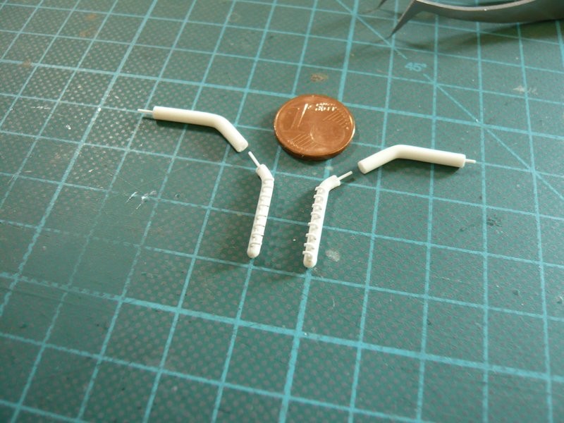
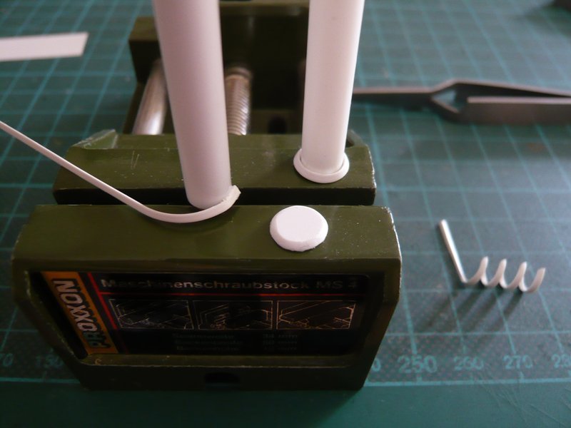
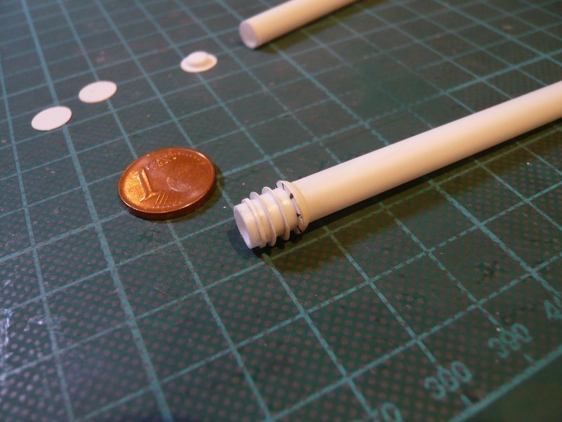
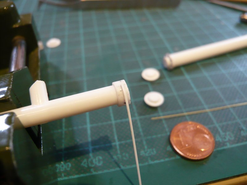
nothing is impossible, and therefore I want to show you still on the fly my announced attempt with the nipple on the prototype of the 6’’ outlet (Ø 1 mm). ![]()
The tiny hole on the bend I have predrilled with my smallest drill with Ø 0,2 mm. And then I have been amazed, as I have found in my remeasuring of the 0,3 mm rods that they are a little undersized, approx. Ø 0,25 mm, and accordingly might fit well. ![]()
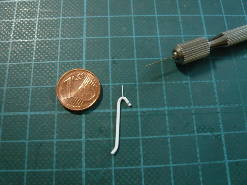
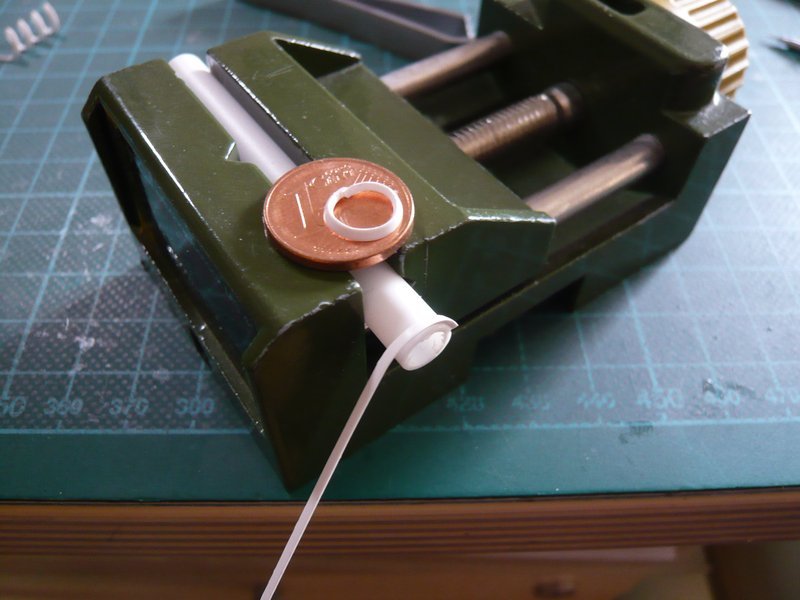
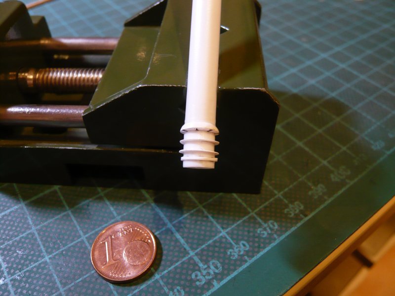
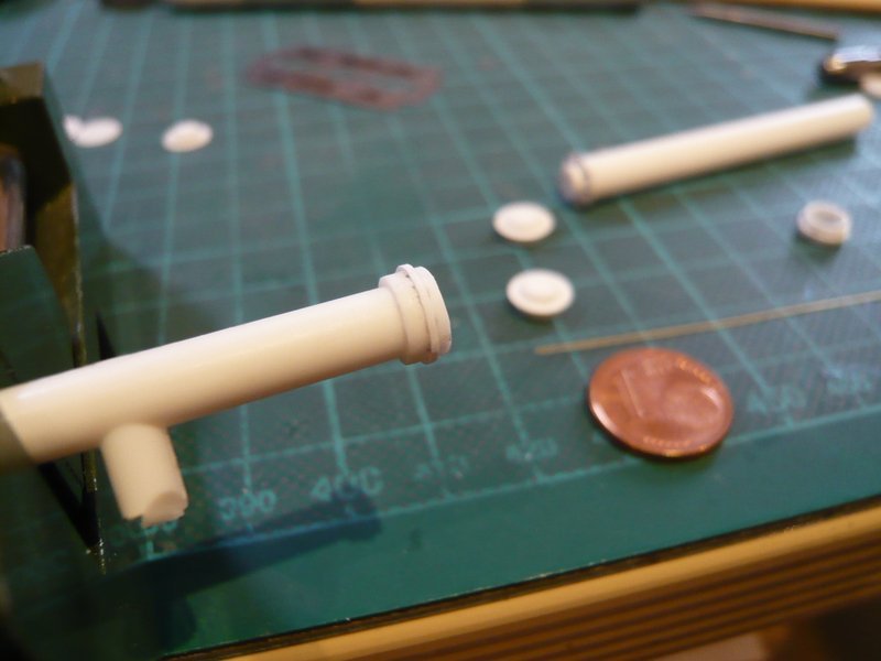
After the little rod was glued with MEK and shortened, the outlet with the tiny nipple looks like this. ![]()
And so also this detail on the thinnest outlet has been mastered, especially as the clamping rings are far less problematic. ![]()
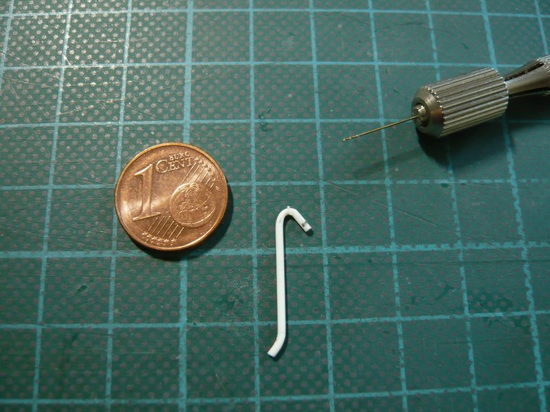
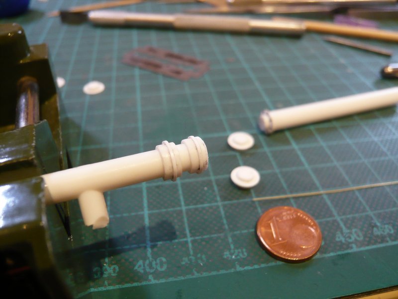
But Stop! Do you notice anything? ![]()
![]()
3 Likes
Well, since you posed the question, I will venture to guess that the nipple might be slightly out of position? If the short end (with the black mark) is supposed to be vertical, then the nipple’s current position is not at the highest point on the bend. Not something I would notice if you hand set me to looking so closely.
![]()
1 Like
Yep, my friend, you hit the nail on the head, congrats! ![]()
Only upon closer inspection of the image I have noticed two things in retrospect which require correction. ![]()

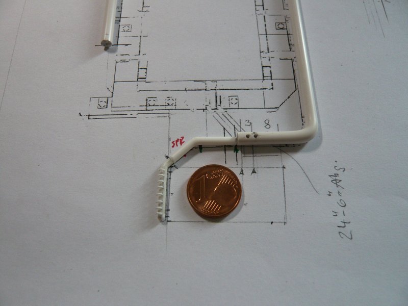
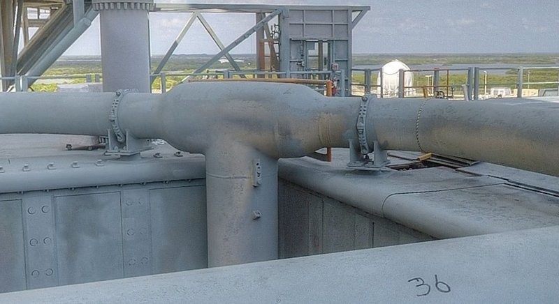
Firstly, one can clearly see that the orientation of the nipple (red) does not match with the intended installation position of the outlet on the 24’’ ring line (green), ![]() what has to be initially escaped me out of overeagerness.
what has to be initially escaped me out of overeagerness.
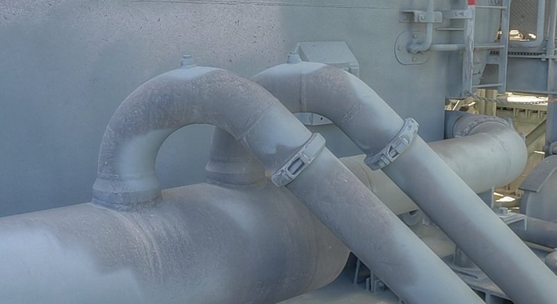
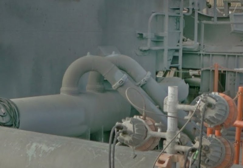
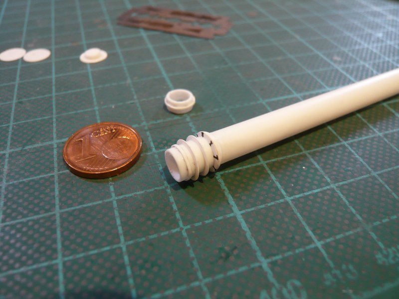
And on the other hand can be recognized from this photo that the bow is rounded rather like a crooked stick and has a larger opening angle than the previous. ![]() Accordingly, the rounding starts directly above the connection point on the ring line and not only after the vertical ascent like at my prototype.
Accordingly, the rounding starts directly above the connection point on the ring line and not only after the vertical ascent like at my prototype.

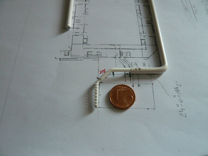
Since that is not so good visible in some photos due to the perspective distortion, I have twisted the following panorama image as long as until the best direct view of the two outlets has revealed, which is similar to the previous image.
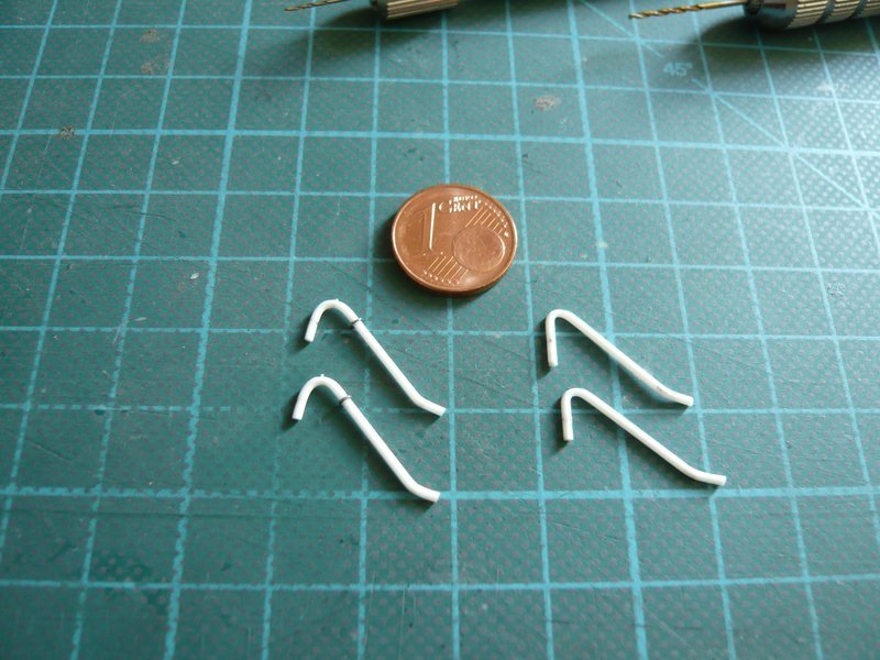
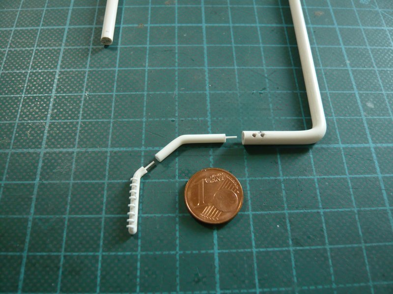
Therefore, new outlets were needed with greater rounding, on their highest points the nipples were inserted,
what looks much better now. ![]()
Here once more the comparison of the outlets, whereas the two new outlets (left) have their clamping rings already.
And now to the next step, the adaptation of the nozzle tube (Ø 2,0 mm) to the ring line (Ø 4,0 mm).
For this purpose, the tube was separated after the bend at the TSM corner because there the connecting piece to the ring line starts, which was bent from a rod (Ø 2,5 mm).
To align the course of the parts better before the final bonding, I have drilled the parts with Ø 0,5 mm and then inserted appropriate connection rods.
This allows plug together the strand, whereby the test-fitting on the MLP is facilitated and any necessary length corrections are possible.
And only when everything fits, the parts are then glued together. ![]()
![]()
4 Likes
Hello everybody,
yeah, my solution with the plugged-together-strand has actually paid for itself well. ![]()
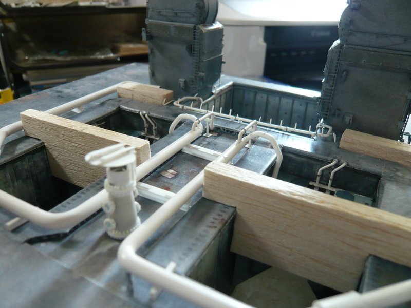
And this strand I’ve tried on on the MLP, initially with the Dummy TSM, because this is much simpler than with the unhandy real TSM. And lo and behold, a slight shortening of the intermediate piece (Ø 2,5 mm) was necessary actually,
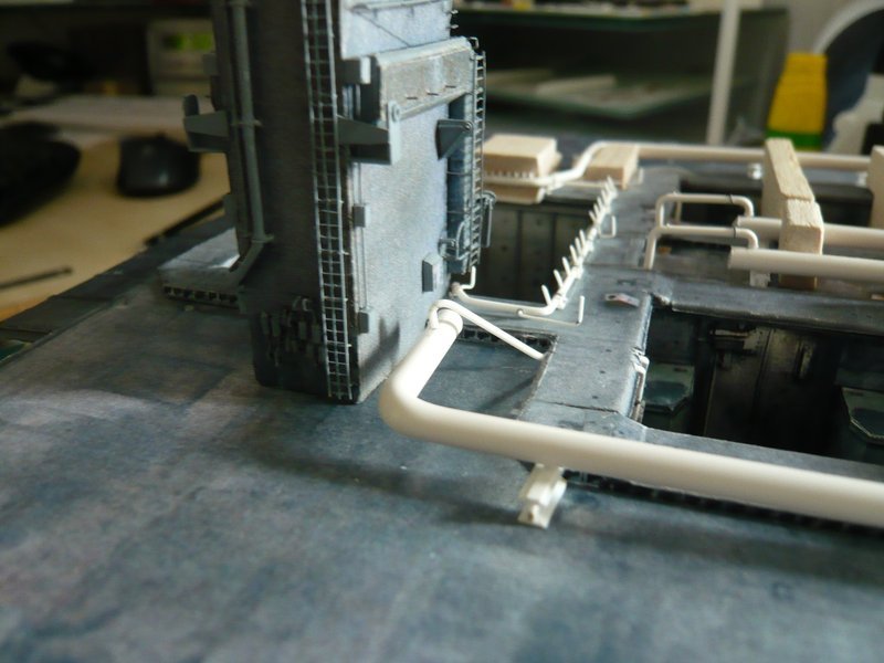
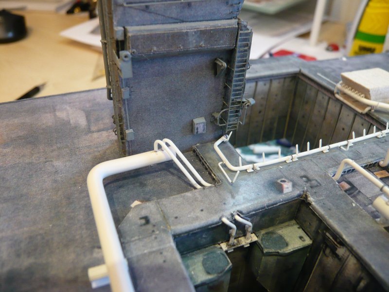
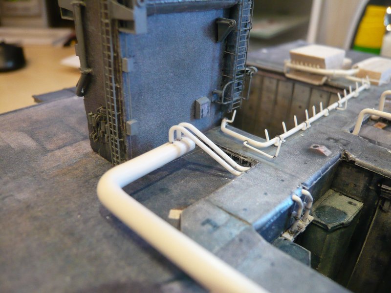
so that the nozzle tube just so fits around the TSM corner and does not protrude too far. ![]()
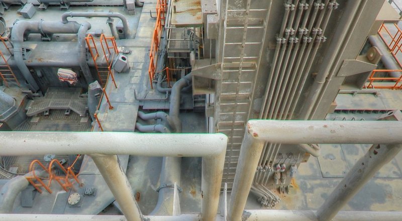
But the acid test came then with the real TSM, and as I had feared, it was really quite closely at the corner,
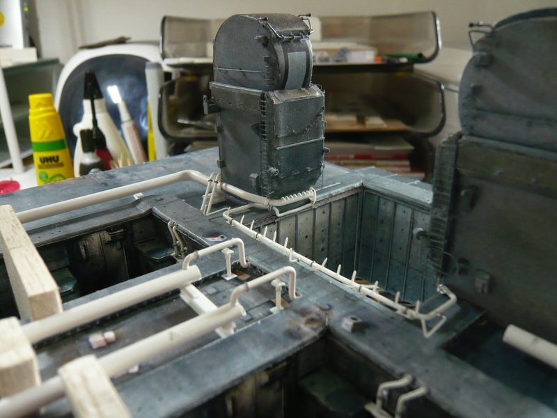
as one can see here,
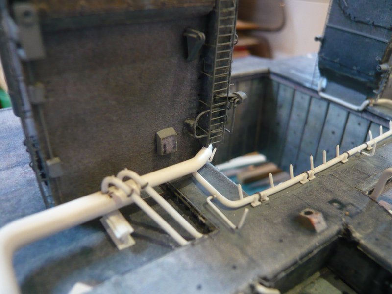
across the Firex line and below the ladder through, and left past on the angled nozzle. ![]()
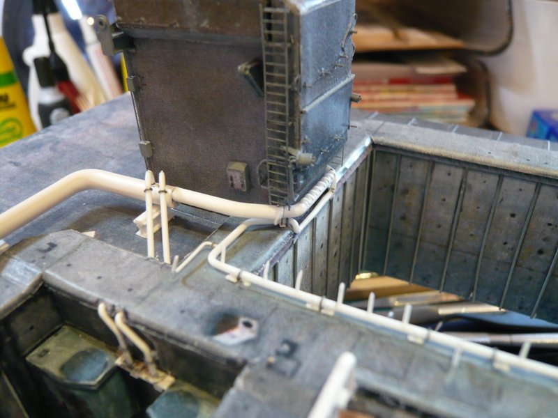
Good that it was not tighter, but fortunately it has worked well. ![]()
![]()
5 Likes
Hi everyone ,
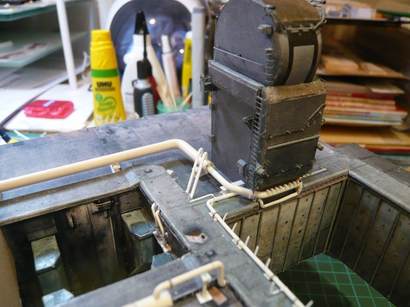
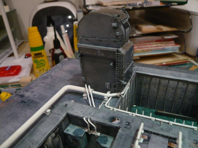
after a little forced break it should now go further. ![]()
At first there is still the supplement to the nozzle pipe on LH2 TSM, which now also waiting for the final assembly and mounting to the 24’’ ring line, which will follow soon. ![]()

And so I would then also have crossed through the maze of SSWS pipes. ![]()
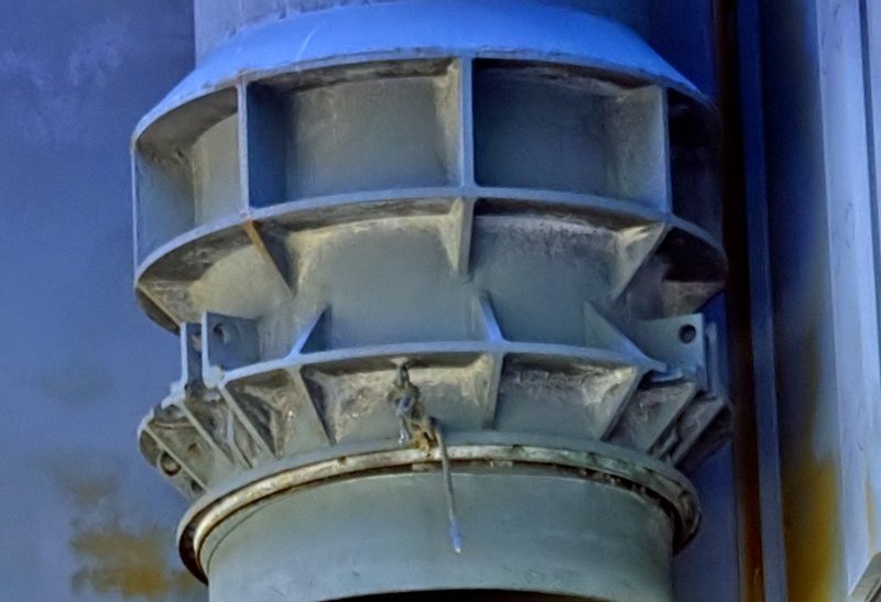
After lately the pipe diameters became smaller from 24’‘-18’‘-16’‘-12’‘- 9’’ down to 6 ‘’, it now once again goes back to the thickest 36’’ pipes (Ø 6,3 mm), through which both ring lines being supplied with water. The connecting pieces of the feed pipes in the corners of the SRB chambers I had mounted already during bending of the ring lines.
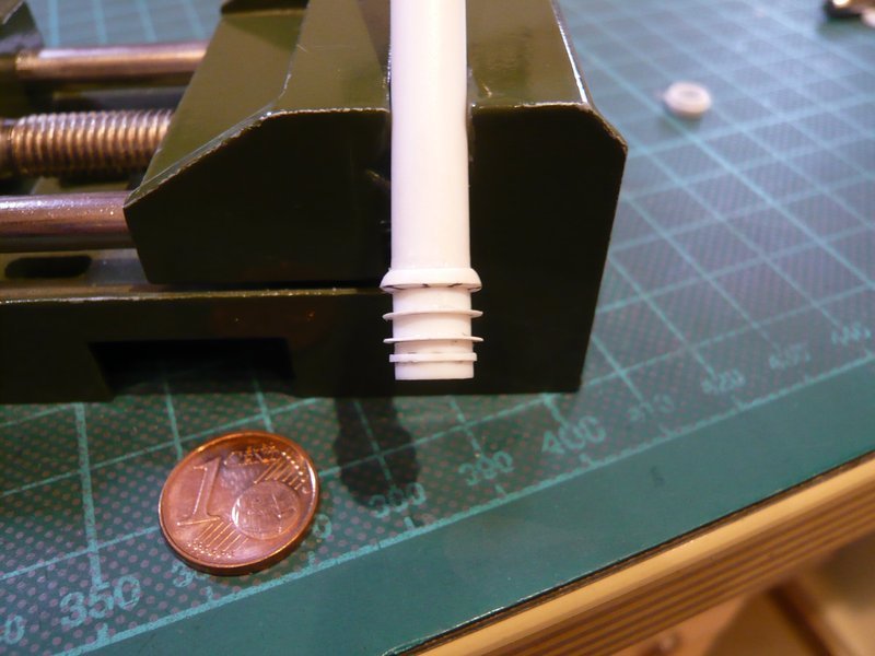
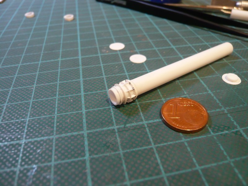
And now it comes to the lower end of the tube with the connecting piece, for whose items I have again estimated their dimensions.
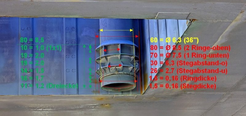
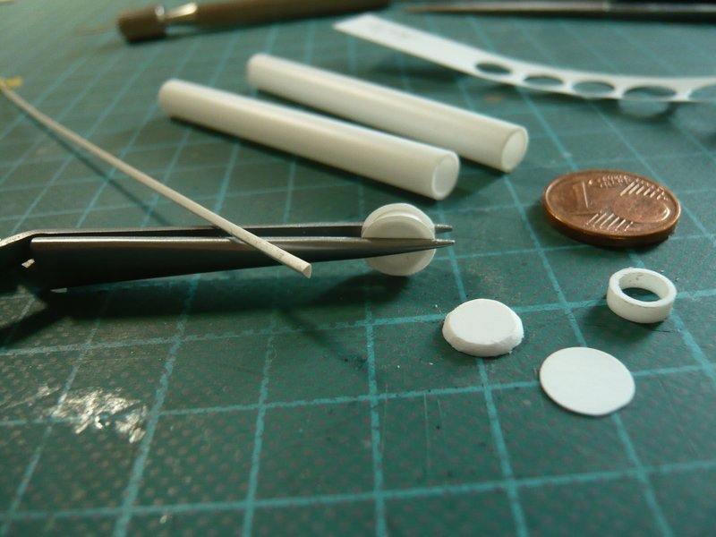
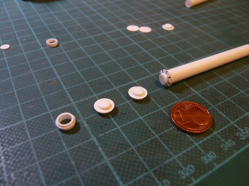
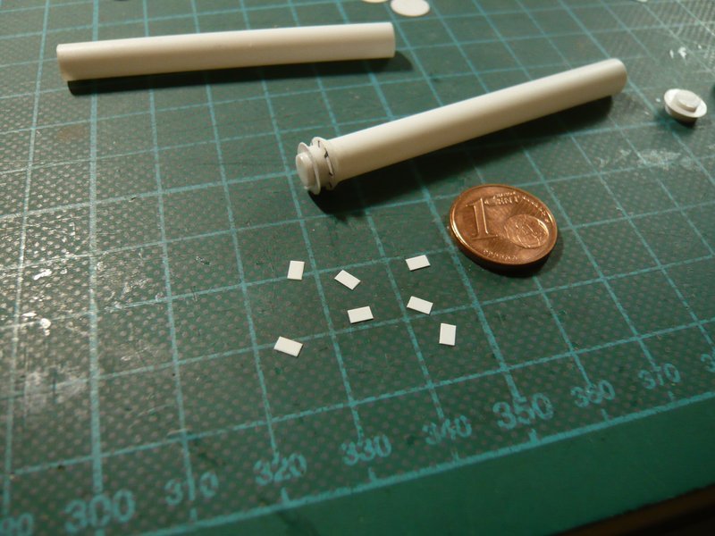
For the construction of this connecting piece I have imagined that I could cut the 6,3 mm tube into short rings, which are subdivide by punched plastic discs (0,15 mm) and finally are glued together. ![]()
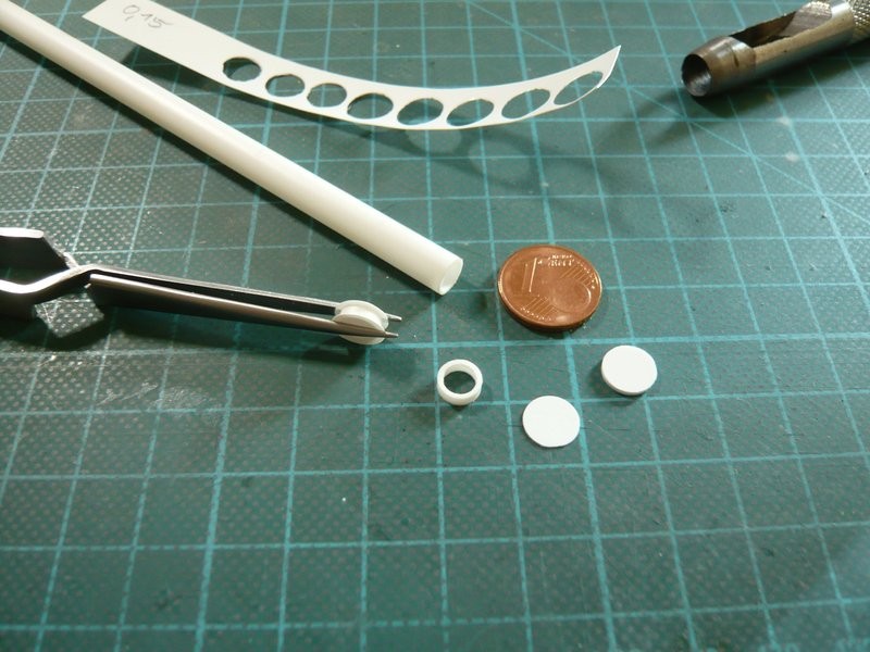
The more difficult part of the exercise subsequently follows, when these tiny stiffening ribs and corners must be glued all-around, for which I already have an idea, ![]() but what could become quite a tricky fumbling.
but what could become quite a tricky fumbling. ![]()
As far as for today. ![]()
![]()
4 Likes
Why not use groove method where the rib is one piece like a pyramid with a center u cut removed. The ring has a u cut as well at the rib location. As an idea.
1 Like
Wait and see, Ryan, the matter is a bit more complicated than you think. ![]()
1 Like
Hello together,
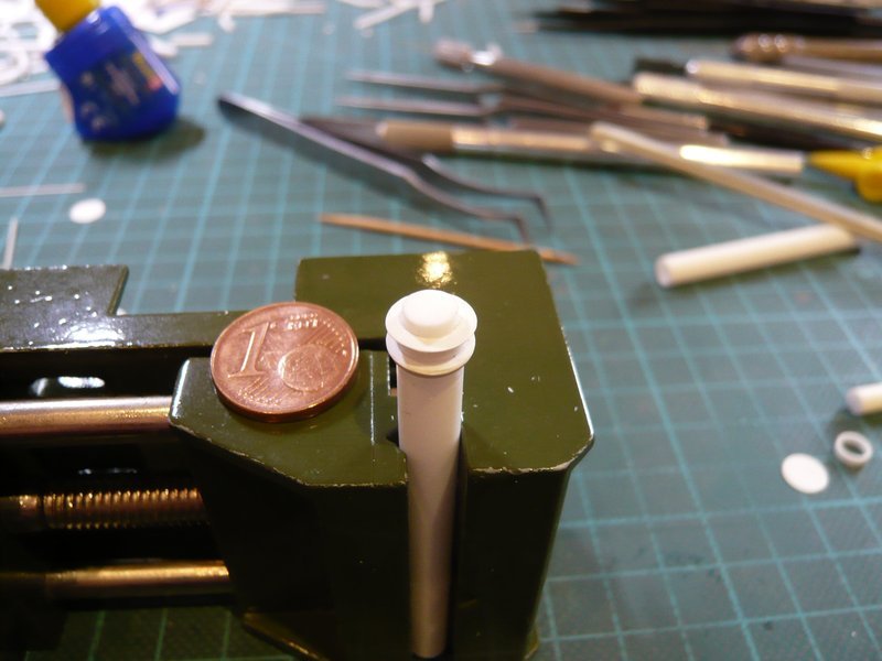
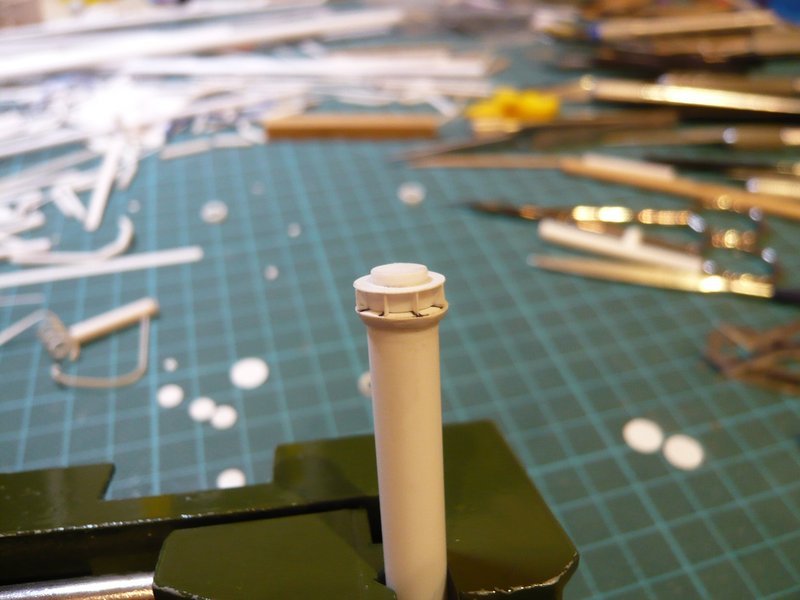
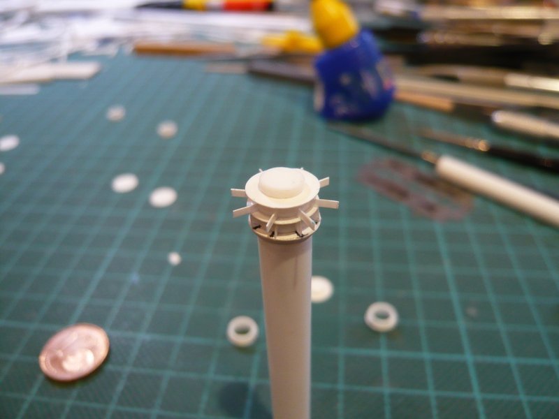
before the tiny stiffening ribs and corners get their turn, the subdivided construction of the connecting piece must first be put into practice what I first have tried, whereby I proceeded from top to bottom. ![]()
This starts up on top with this conical ring (truncated cone), about which I’ve been thinking. ![]()
One possibility would be to file off a circumferential 45° bevel to a 1 mm thick slice (Ø 8,0 mm), what is tedious and not easy if it should become perfectly round, as one can see. ![]()
Then one could also imagine a ring of triangular profile (60 °), as can be seen on the tweezers. That is not of Evergreen, but in an architecture shop I have found and was very happy. ![]()
But already at the hot bending of the Rings proved the profile to be quite stubbornly because it has aligned to the wood core, as it wanted,
and has also still twisted itself. ![]()
Thus, it could not so nice and smoothly be attached to the 36’’ feed pipe (Ø 6,3 mm) as I would have liked. As can be seen, namely a gap emerged at the top, what I do not like and still has to be filled somehow. ![]() But then one could also mould the bevel with Apoxie Sculpt.
But then one could also mould the bevel with Apoxie Sculpt. ![]()
So I wanted to try something else and have glued a slightly pre-bent triangular strips all around with CA.
Although this has worked a little better than before, but a smaller gap could not be avoided altogether. ![]()
But with the result I first times contented myself in order to test the further construction. But I definitively did not wanted to glue together the rings and discs in order to make even possibly corrections of segment heights. That’s why I have cut small 1 mm base plates of a sprue, which correspond to the inner diameter of the rings. ![]()
These plates should serve as a base, on which then the rings are placed loosely without glue.
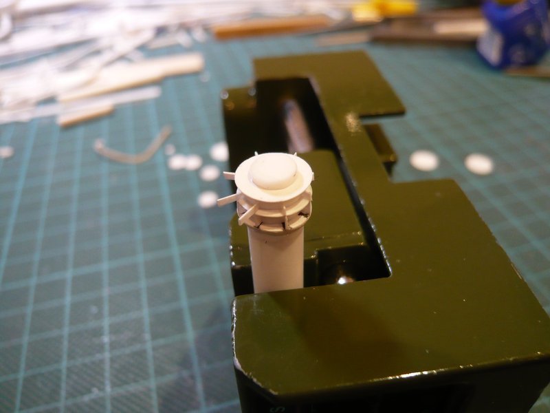
Then followed the stepwise construction of the connecting piece with the parts, whereby one has to pay attention on a central alignment of the slices and rings. ![]()
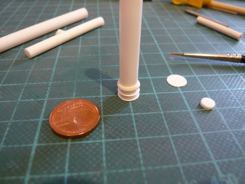
On the lower tubular segment of the connecting piece sits a double-profile ring, as can be seen in this image.
In order to scratch this ring simplified, I glued an Evergreen strip (0,4 mm x 0,5 mm) around the lower tubular segment.
Then I have put together all the segments, whereby the connecting piece slowly takes its shape.
However the lower ring appears a little too massive, maybe a strip 0,25 mm x 0,5 mm would look something more pleasing from what I could still try, ![]() especially because the connecting piece still can be disassembled.
especially because the connecting piece still can be disassembled.
Now then are still missing the stiffening ribs and corners, which I will make next time. ![]()
![]()
5 Likes
Hello everybody,
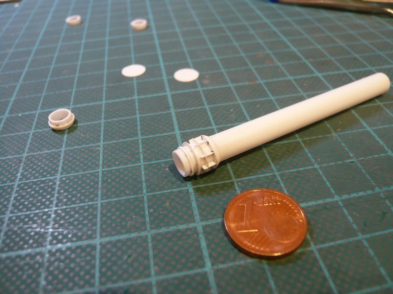
as already indicated, the lower ring of the connecting piece I have still slimmed down a bit and by using a thinner strip of 0,25 mm x 0,5 mm. ![]()
And in a direct comparison of both rings the optic of the new ring (right) looks something more pleasing, I think so, ![]()
but that is as always a matter of taste. ![]()
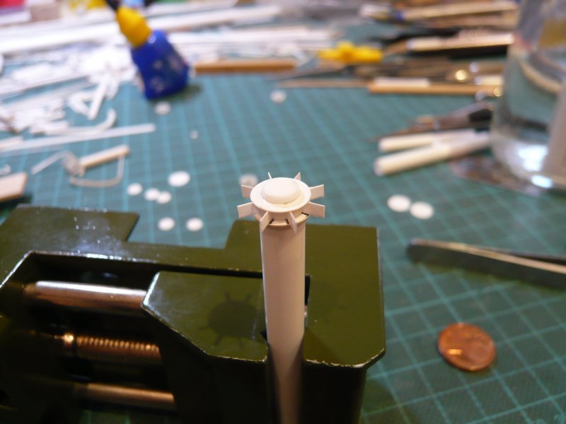
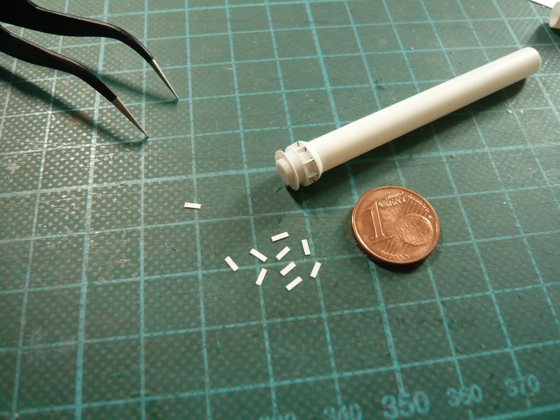
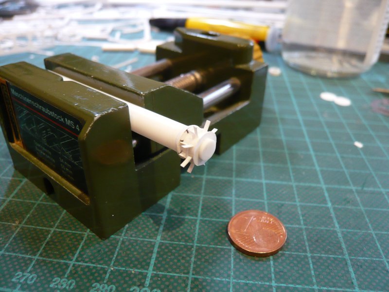
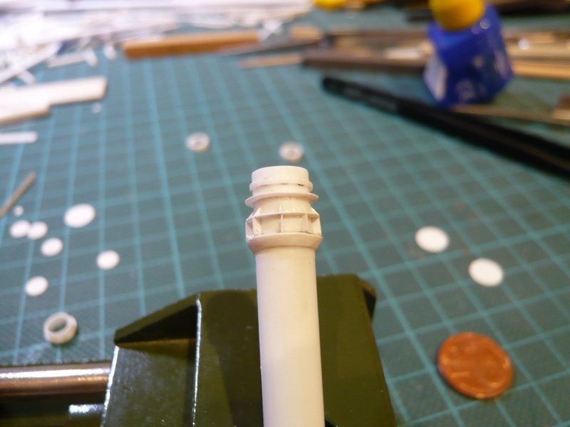
And now followed the upper eight stiffening ribs, for what I have cut short Styrene strips (0,13 mm), which are a little longer in order to assemble and glue easier, ![]()
which I have again done with MEK.
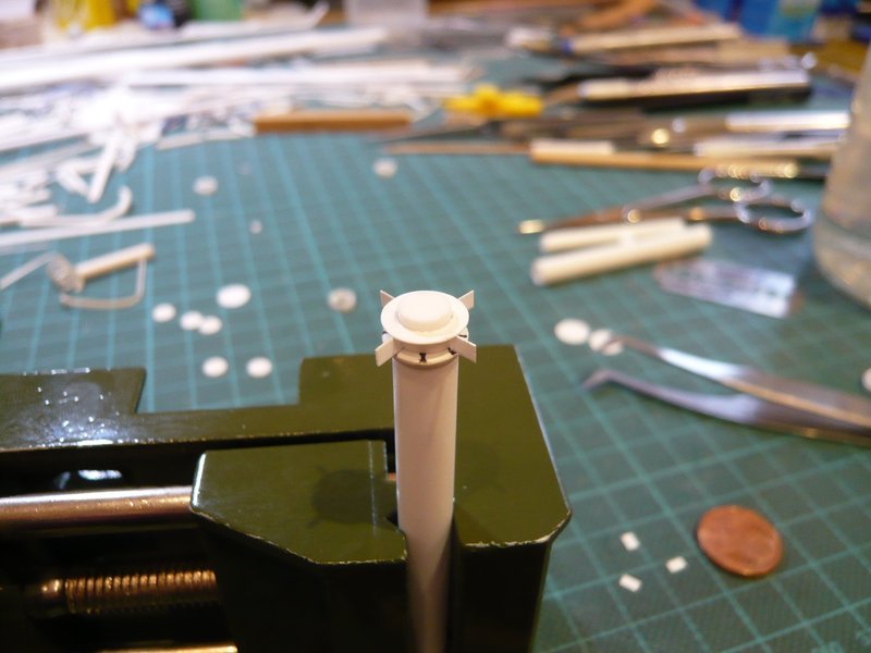
But do not worry, I’m not on the wrong path, this should not become a turbine rotor. ![]()
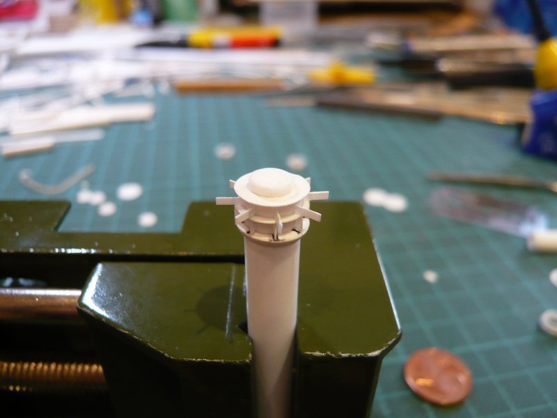
And now only the protruding ends had to be carefully cut off with a razor blade from top to bottom,
which has worked pretty well. ![]()
However I fear, that the tiny stiffening triangles certainly shall become much more complicated and stressful. ![]()
![]()
5 Likes
Insanely tiny detailed work. Everytime I open your build its more impressive.
2 Likes
I have had to go for 5 extra eye tests since this build started lol !!
2 Likes
Thanks Barney for your nice compliments and stay tuned for more fun. ![]()
![]()
OMG John, sorry for your problems. But take comfort, I recently had to sit for a Nano laser surgery on both of my eyes. ![]()
![]()
2 Likes
Hello folks,
to be frightened is not an option, ![]() so please fasten your seat belts!
so please fasten your seat belts! ![]()
And so I have got down to work, whereby the manufacture of the triangular stiffening ribs happened according to the same recipe for success. ![]()
First, I have cut 0,8 mm wide strips of 0,13 mm Evergreen Sheet Styrene and separated from these then 3 mm long sections.
But now came the gluing, and I first tried with the normal Revell glue. But due to the minimal contact zones (0,8 mm x 1 mm) it is quite problematic to establish a sufficiently strong connection. ![]()
For the fixation of the strips it was initially sufficient, but if they would survive the reducing of the overhangs, I was not sure. ![]()
Therefore I wanted to stabilize the contacts even from both sides with MEK. But that failed because the MEK dissolves the contact point too strong, whereby the strip has lost his footing and tipped over. ![]()
At the 2nd attempt I have therefore fixed the strips initially only with CA, but this is quite difficult because the correct location must be found immediately and the seat almost can not be corrected. But with a little practice and a quiet hand then I have succeeded. ![]()
And after that, the strips then could be stabilized with MEK yet again. ![]()
In this position I then first have cut off the overhangs perpendicular with the razor blade.
And then I have gently cut off the 45° bevels, which to my surprise was actually relatively easily doable. ![]()
And now I’m actually quite confident that I will be able to scratch the remaining triangular ribs on both sides of the lower disc also. Upon closer examination one can see, that there are about twice as many ribs as on the middle disc, which are also unevenly distributed over the circumference. ![]()
And then there are as a further delicacy still three pairs of rectangular ribs (0,8 mm x 1 mm) with holes (Ø 0,2 mm), which are staggered to 120°, ![]() whereupon I cannot probably renounce, or maybe yet?
whereupon I cannot probably renounce, or maybe yet? ![]()
Let’s see what we can do! ![]()
![]()
6 Likes
Lovely precision work ![]()
2 Likes