Thanks John, then I’m satisfied.
Stay tuned and keep curious. ![]()
Thanks John, then I’m satisfied.
Stay tuned and keep curious. ![]()
Hello everybody,
before modification of the tips I’ve been looking once again for photos, on which the position of the SRB Aft skirts on the Hold-down posts can more accurately be detected. Mine is still not clear whether the SRB Aft skirts are on a level with the SRB Blast shields or slightly higher. ![]()
But now I have found a photo from the VAB and one can see, that the front SRB Aft skirts nearly lay on the same level with the Blast shields. ![]()

Source: www.flickr.com (S. Patlan)
Then I looked at even closer the Hold-down posts on the SRB supports, to see whether something scratch-building is possible. Somehow I feel like back on such things after the stupid demolition work. ![]()

Source: NASA
As you can see the cone tops sit still on small bottom bases, it certainly seems to indicate. The red caps are small Blast shields, which are shielding the “explosive charges” (NASA Standard Detonator) in the Frangible Nuts of the SRB Hold-down Studs. These blast shields are missing on the front Hold-down posts, why ever. ![]()
The drawing in the following image shows the structure of a complete Hold-down Assembly.

Source: NASA
Inspired therefrom, I’ll try to reproduce the upper cover plate (Aft Skirt Shoe) and the side fixtures (Shoe Retainer Mechanism). 
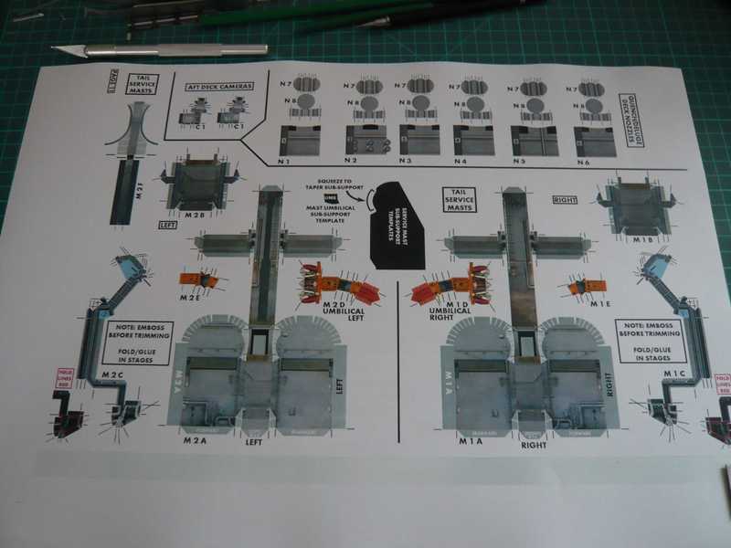
Here are some parts that I need for this. I’ve punched me the bottom bases (8 mm) with a hollow punches from 1,5 mm sheet. For the studs, I’ll use 0,5 mm brass rod,

and for the Aft skirt shoe a rectangular profile 4x1mm, which is sitting up on the top of the cone in which I will paste a 3,3 mm plastic rod. The side fixtures could be indicated by 1 mm plastic rods.

Of course separated connecting bolts, for what one could use sheathed copper wire (1,2 mm) would look better.

Then I still somehow have to mount the small grey Blast shield, the red painted shields like on the photo was probably only used on later missions.
I’ll try this assembly group then next time. ![]()
![]()
At a loss for words. What an undertaking! Following with great interest.
Thanks Evan for your interest and stay tuned. ![]()
Because the Aft skirt hold-down posts of the SRBs with 2 mm are very narrow, ![]() I have carefully pre-drilled the holes for the bolts (0,5 mm) for the fixing of the stack with the gimlet first with 0,5 mm,
I have carefully pre-drilled the holes for the bolts (0,5 mm) for the fixing of the stack with the gimlet first with 0,5 mm,


and drilled then for easier threading of the stack to 0,8 mm diameter.

And the Hold-down posts are constructed from these parts.

The cone tips get cores of a 3,3 mm rod with a 0,5 mm hole for the reception of the bolt pins (0,5 mm). The cone tips sit on a base plate (1,5 mm) and receive above as the Aft skirt shoe a small plate from sheet 4 x 4x 1 mm.

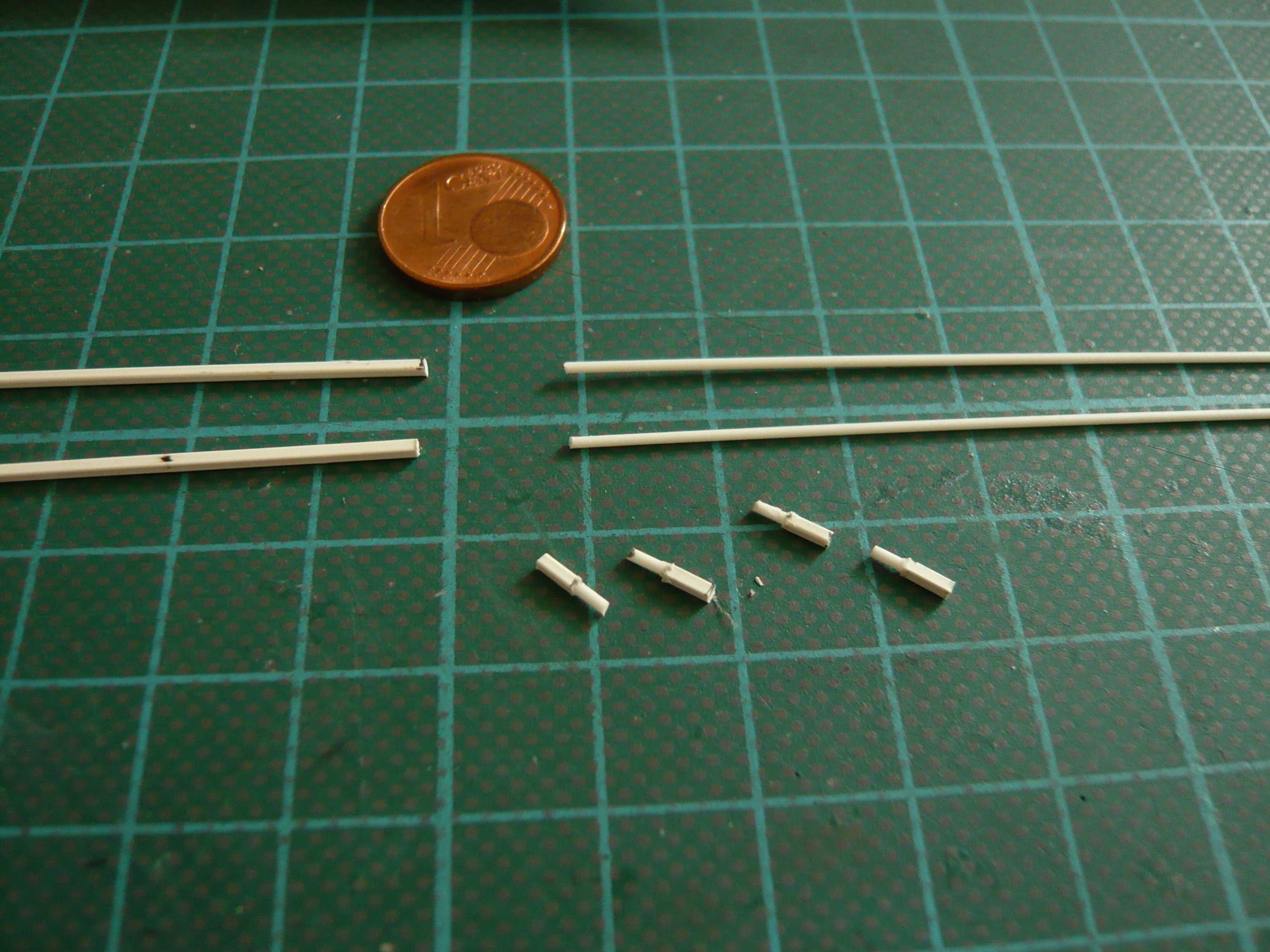
This is now such a pre-assembled body for the Hold-down post (left) and next to it an attempt for the side locking pin of the Shoe retainer mechanism, which however still not convinced me.


Since this solution with the coated brass wire (blue) seems manufactured bit too time-consuming from processing, I further considered and once cut the rods.

Therefore here now another attempt made of plastic with a square profile (1 mm), with a glued rod (0,8 mm) as bolt.

This allows then but easier to produce and I like even better, as you can see on this image. ![]()

And so I will also build now the remaining seven Hold-down posts. And most recently the small Blast shields come then to the top of the rear Hold down posts. ![]()
so much detailing … my eyes hurt haha
Now it went a little further with the Hold-down posts again.
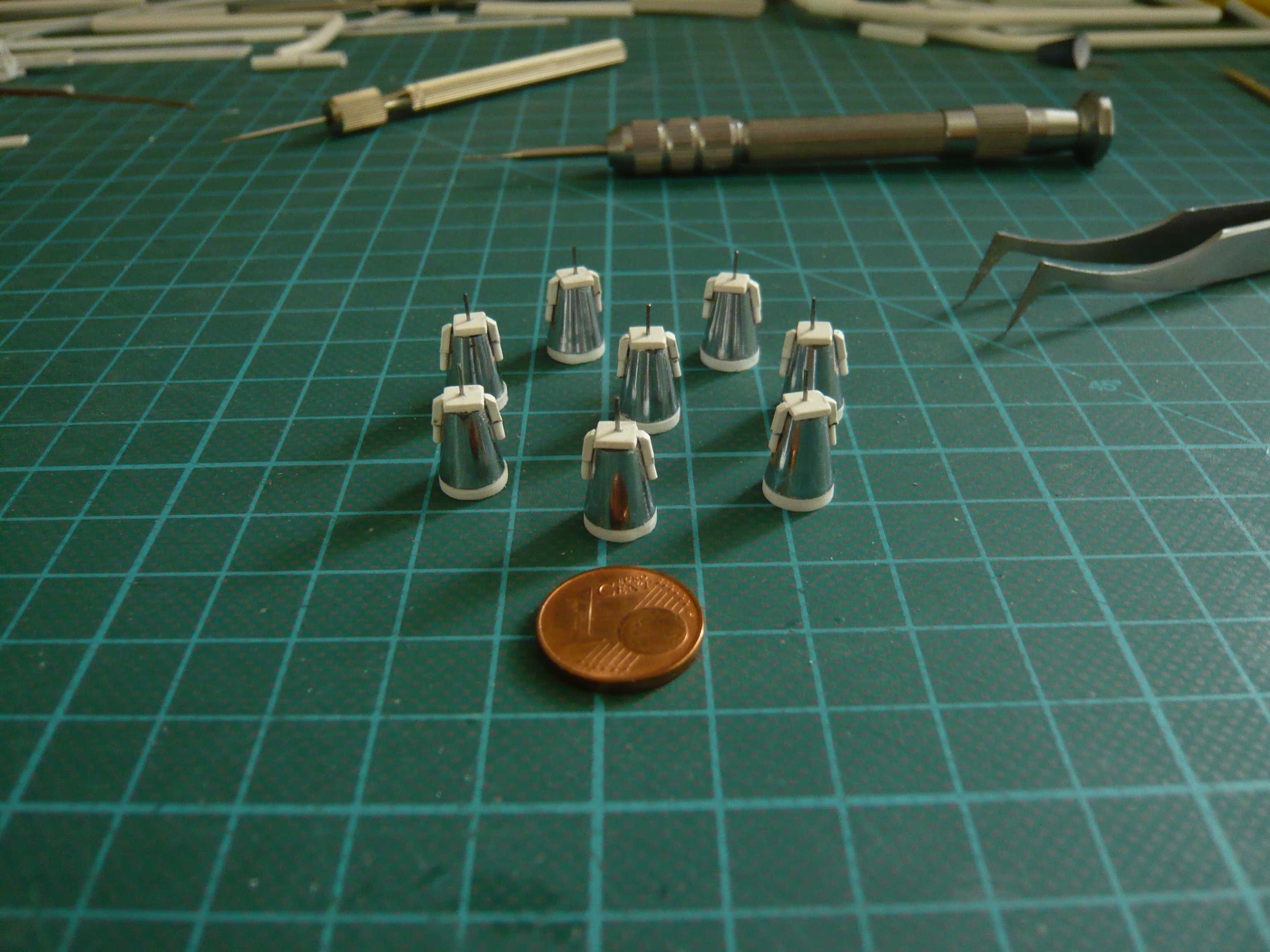
These are the necessary items for the remaining seven Hold-down posts, until on the lateral retaining bolts of the Shoe retainer mechanism.

After the cone tips were shortened to the required height, the rods (3,3 mm) were cut and received a through hole (0,5 mm). Then they were pasted in the cone tips and then glued onto the bases.

On the top the small plates (Aft skirt shoe) were then glued, and yet the 0,5 mm bolts were glued into the holes.

Since the parts for the side locking bolts are only such short stubs of about 2,5 - 3,5 mm, it is better, if only together sticks the profiles,

and cuts only after drying on length, so this is really easier. ![]()
Now the stubs only on both sides must be glued,

and then they are available for painting.
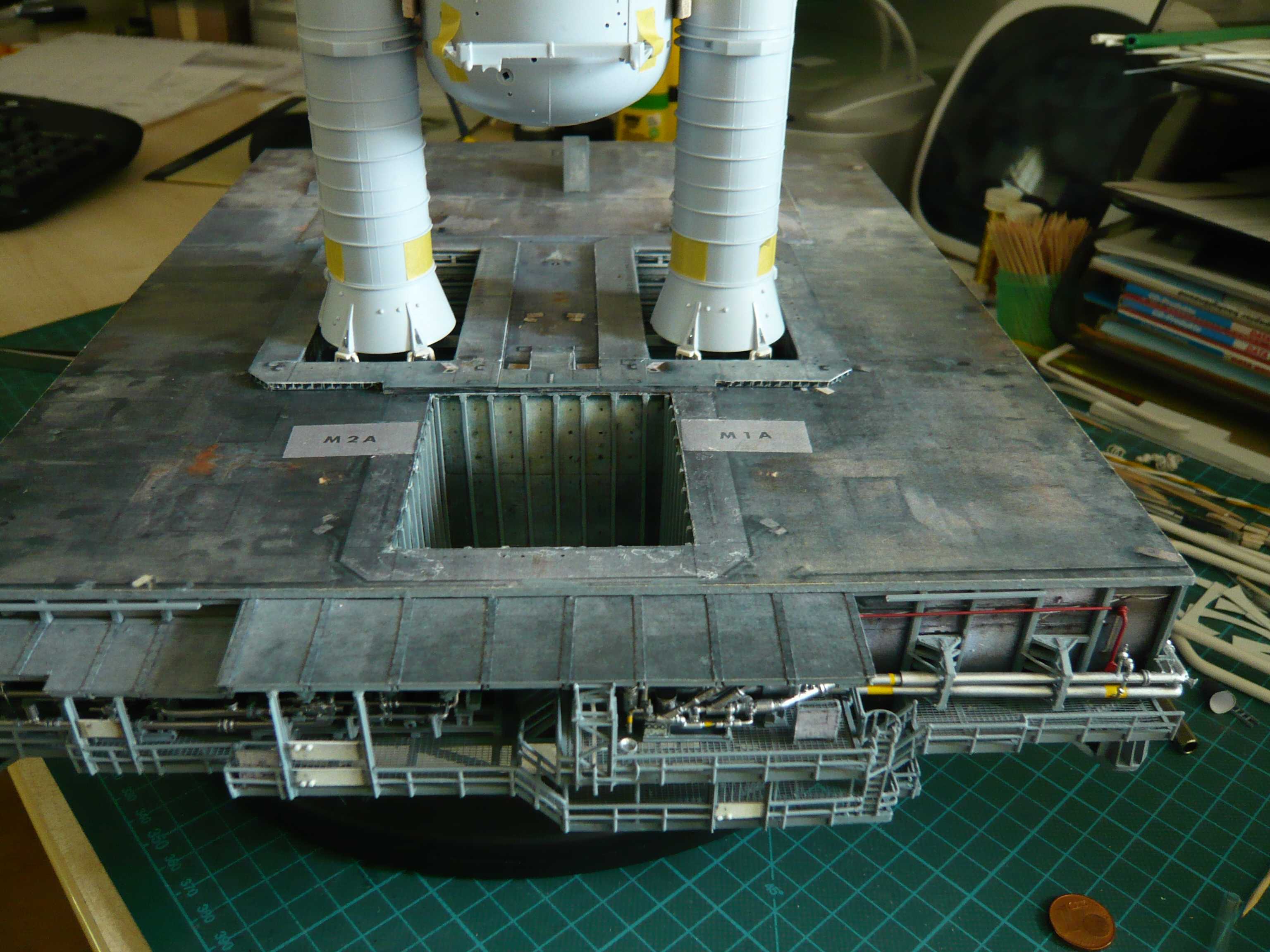
But before there is another alignment test on the support, ![]()

and so the Boosters are standing on it.


And if the Hold-downs are first then painted and will stick firmly to the supports, then I can breathe again. ![]()

As far as for today. ![]()
Only started reading this topic today… incredible, don"t know what else to say…
Thanks my friend for your compliment, stay tuned and you will see a lot of other crazy scratch modeling. ![]()
Hello everybody,
as I’ve reported earlier I’ve decided building the Tail Service Masts (TSM’s) once more in 1:144 by using David Maier’s Paper kit templates. ![]()
But there is also another problem.  When fastening the SRBs on their supports and hold-down posts, I must note that the stack cannot stand without a prop under the orbiter and therefore needs a support. When the stack is built it’ll have some weight and the orbiter will make it heavier on one side.
The eight pins (0,5 mm) in the hold-down posts serve only the fixation of the stack on the SRB supports. I’ll chose the slightly larger bores (0,8 mm) in the SRB aft skirt hold-down posts only in order to be able to thread the stack better over these eight pins.
A solution for the support of the stack, I’ve been thinking a long and I have some ideas for scratch-building it.
First of all I imagine a horizontal support bar, which runs through both TSMs and the orbiter, in the height of the Umbilical interfaces. The bar could be one-piece and continuously, or I could imagine two shorter rods, which are inserted from both outer faces through the TSMs into the orbiter. These bars are likely to be hardly to see in the TSM walls. 
This solution could also work, if the TSMs are not glued on the MLP deck, but if the TSMs with this support bars through the umbilicals are only placed near to the orbiter and support him so. Then, you have to find a solution to the TSM SSWS pipes.

Source: NASA
A second solution would also be possible:
In both SRBs bottoms threaded rods are screwed from below, ranging through the SRB holes a few millimeters over the MLP ground. On these threaded rods a hold-down clamp made of a metal strip (85 x 5 x 2 mm) is screwed with nuts. Then you might not need a support rod through the TSMs if the orbiter would be fixed by the double umbilical connections.
Currently I tend to the first solution with one or two rods in the TSMs.
And this is the way I want to go, because I think that the lateral support rods from outside the TSMs through the Umbilical into the orbiter seems to be the best solution for stabilization of the stack.

Source: NASA
I think, because there already some pipes and cables run through this interface, the support rods will hardly attract attention.

Source: NASA
Maybe I can still think of a better solution too. ![]()
Hello everybody,
and now I turned back again to the TSMs, but this time in 1:144, otherwise the same procedure like ever in 1:160.
In the Paper Kit’s building guidance all steps are illustrated in detail.

Although both TSM’s from the outside form look almost alike, they differ nevertheless in some details, which will still have to be seen. I began first with the right TSM, by which the pipes for the Liquid Oxygen (LOX) run.

All who wants to see the further constructing procedure in detail can follow the whole TSM chapter using this link.
Only a short view with the comparison of both TSM’s, 1:144 vs. 1:160.
And the “big” TSMs on the MLP look like now.

And here again compared the 1:160 TSMs in front of the 1:144 TSMs.

Thanks for watching and stay tuned. ![]()
And here are a few impressions, such as the almost finished LH2 TSM looks on the MLP, which was not seen for a long time indeed. 
Here you go. ![]()

And with this result, I can be quite happy now, I guess. 


Hello everybody,
but before I start fully in the SSWS chapter again, I wanted to see how a new test with the stack and the 1:144 TSM’s will look like in order to check their location next to the SSME exhaust chamber.
After my first emergency surgery to widen the SRB exhaust holes to 1:144, I had thought of not having to change the SSME hole. But then I made my decision, to build the TSM’s 1:144 too and have started the tricky job with the PE ladders and ROFIs what had distracted me from the scale problems a little bit.
Now I have made a new test with the stack and the larger TSMs (1:144) and see for yourself first, what it looks like now …
First, the sight of the stacks on the MLP is quite impressive again, I think.


With something closer inspection you can see that the TSM’s wandered slightly outwards and forwards, representing each about 4 mm.

In the provisional arrangement I went out thereof, that should be approximately 10 mm space between the TSM hoods and the orbiter for the two T-0 Umbilicals. These are the fold-out “connector plugs” for the media supply of the orbiter during the countdown to lift-off, which can be seen nicely in this top view.

Source: NASA
In the rear view the displacements become even more significant.


And here again, both views without the stack for better overview.


And now it is clearly seen that the two TSMs are too far next to the exhaust hole, so that there would be significant problems in laying the SSWS pipes around the hole, especially in terms of optics if you look at the next picture. This would then probably have a somewhat strange running of the lateral pipes below the service flap box. 

Source: NASA]
And if I imagine this sight, I know that I would not like and for better or worse I will have to widen the SSME hole at about that 4 mm on both sides. This arrangement corresponds then on the width and the location of the TSM’s exactly the geometry of the 1:144er hole arrangement, and that will be okay. Then the TSM’s standing right next to the hole, where they belong, and with the shorter length of the hole to the front I have to live. 
So then let’s go to the 2nd emergency surgery,  which I hope will not be quite as cruel as the first one.
And for that, please press all available thumbs! ![]()
Hi friends,
first of all I had to cope this second low blow somehow,  but still I’m not knockout, but only slightly chipped …
After my first emergency surgery on the SRB holes I was worried that it would probably run out on it, but I had supplanted these thoughts in the meantime again and again. But latest with the decision for the 1:144 TSMs that was really clear, but then I have first built the tricky TSMs and ROFIs and was therefore initially too distracted. But now the vexing dilemma of scale of the Revell kits with the following compromises has ultimately caught me up again. 
However, long wail does not help, and therefore let’s go for the second emergency surgery, I have to go through now. 
The Dremel is already snappy and ready for all infamous actions, and the surgeon has marked out the cuts already. ![]()
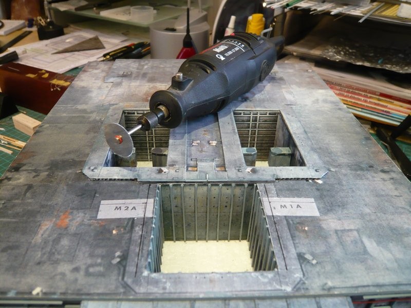
Well, unfortunately that will go again right under the skin, as you can see here.
Because I need to extend the width of the exhaust hole from 58 mm to 66 mm, I might come out in the side walls, but fortunately they are made of balsa. But I guess I will have to remove them completely and to install new walls. Maybe I can save at least the two side panels.
So, I will report to you out of the operating room soon. ![]()
I love it that when you zoom in close and get rid of the work table details and only see the build… It genuinely looks like the real thing…it’s exceptional craftsmanship ![]()
![]()
Thanks John for your pleasant compliments. ![]()
Right now I feel more like a demolition brute ![]() than a surgeon.
than a surgeon. ![]()
Hello everybody,
and stay cool, because now come some crass images, which is not for faint hearted. ![]()
Let’s get ready to rumble! ![]()
And inevitably come back to me the former pictures of my first emergency surgery in my mind. 
But panic is not good, and so let’s go straight to the point. First I tried to carefully peel off the lining of the hole, and at first also somewhat worked.

And then the Dremel with the circular saw blade was in action in order to perform short and painless the two longitudinal sections through the 2 mm thick hardboard on top. ![]()

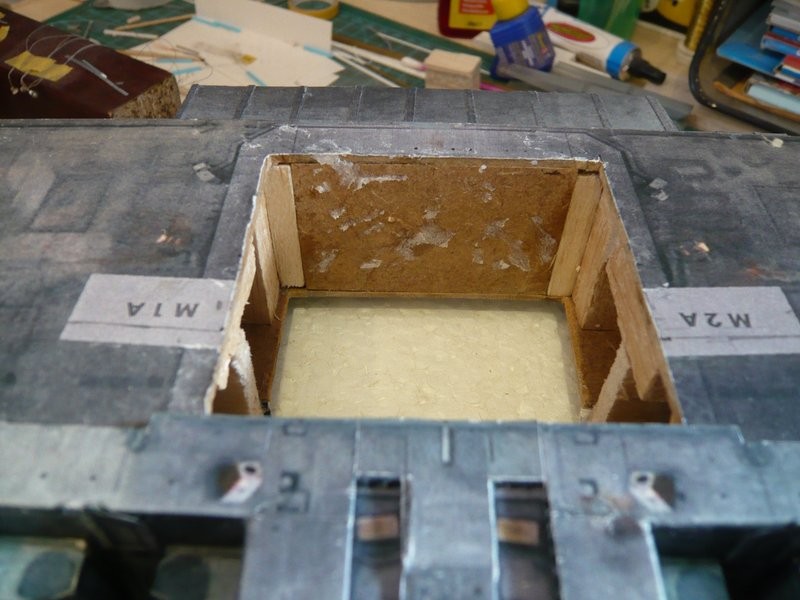
And then, but it went right to the point. In these slots I worked myself with knives and chisels piece by piece into the deep, but that has hurt in my modeler soul what can certainly be seen in the pictures. But unfortunately the lining stayed not entirely unaffected. ![]()


But finally it was done yet, and as you can see, also got a lot shavings flew. ![]()

What a good thing that I wisely chose Balsa wood for the substructure. ![]()

Thus, the rough things are done first time, ![]() and I can make the new wall lining.
and I can make the new wall lining.
Fortunately I can at least still use the reinforcement rods. ![]()
That would of made me cry lol… But it looks like a really nice clean job… Very nice surgery ![]()
Therefore I must be tougher than the rest, John, and never give up! ![]()
And Balsa is just the best suitable material for such repairs. ![]()
Hi everybody,
following the brutal demolition work can now finally start rebuilding the SSME exhaust chamber. ![]()
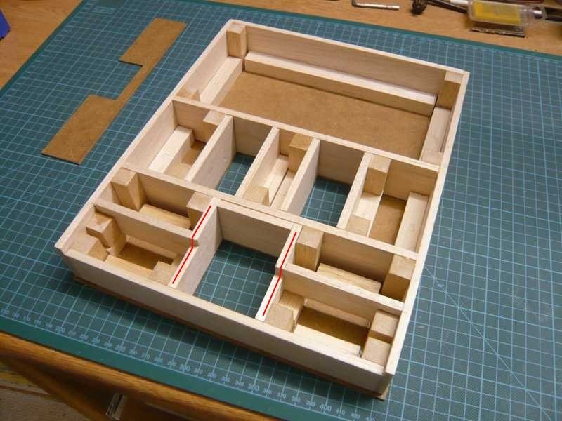
As already indicated, I have completely removed the remnants of the old side walls, so I needed only 2 mm balsa panels for the new walls and corresponding squared timbers for the side columns in the front and rear walls.

First I glued the squared timbers in the front and rear walls.

This was followed by a last test with the angle whether the two openings in the upper deck and in the underbody sit exactly one above the other, which was so far okay.

Thereafter, the two side walls were glued,

and the last test has confirmed the perfect location as expected. ![]()

For the lining of the chamber I had still the original templates from the Paper Kit (1:144) in reserve, which I will use now.

And hence the matter would be corrected already almost. ![]()