Thanks John, this scratch building process is pretty tricky but it’s moving along, therefore fingers crossed. ![]()
![]()
Thanks John, this scratch building process is pretty tricky but it’s moving along, therefore fingers crossed. ![]()
![]()
Hello everybody,
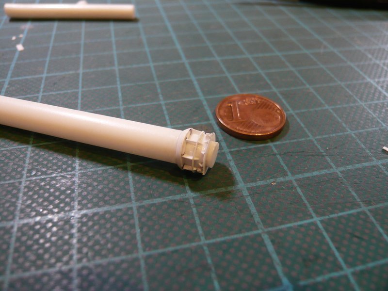
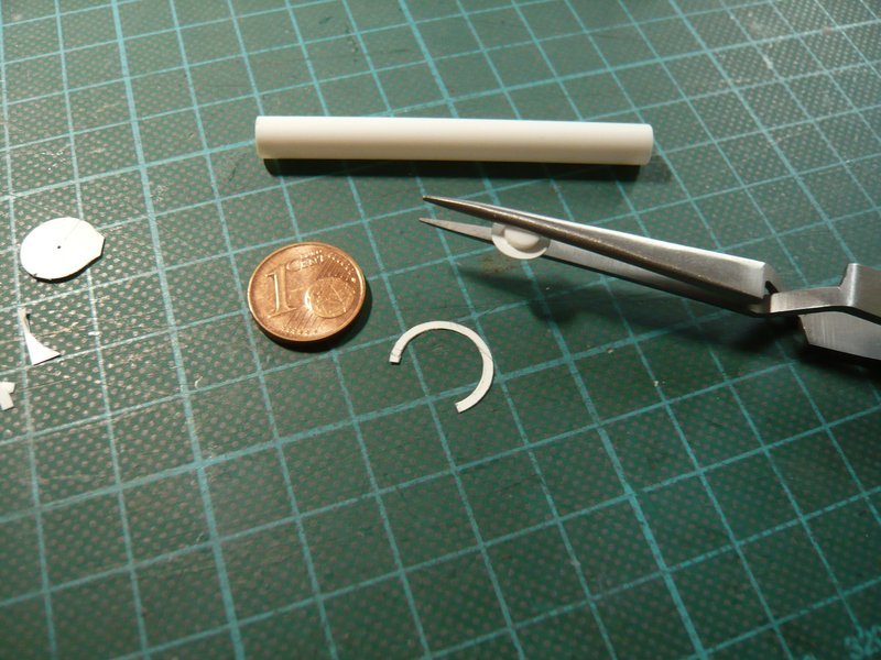
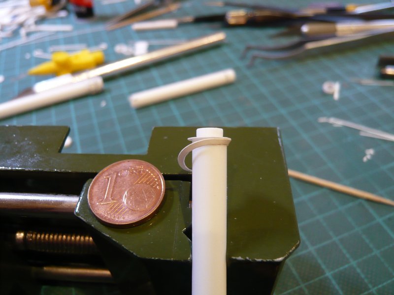
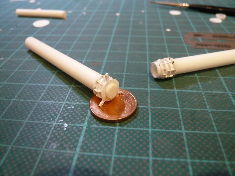
here it goes on with the tricky puzzle at this connecting piece. ![]()
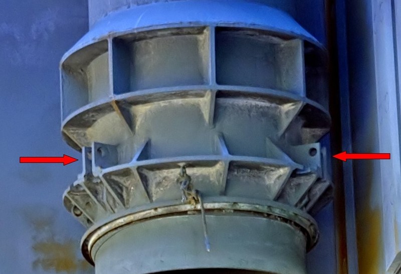
Initially, I have made intensive image analysis once more in order to accurately understand how these 30 ribs are arranged on the circumference of the pipe end, especially since one can always see only certain partial areas on most photos. ![]() And after I had reasonably decrypted the arrangement from the optics, the laborious measuring and scaling were started in order to determine the required dimensions and clearances for the scratch building, I can tell you …
And after I had reasonably decrypted the arrangement from the optics, the laborious measuring and scaling were started in order to determine the required dimensions and clearances for the scratch building, I can tell you … ![]()
The starting point for the determination the position of the triangular ribs on both sides of the 3rd ring was the 120° arrangement of these rectangular pairs of ribs (0m8 mm x 1 mm) with the holes (Ø 0,2 mm).
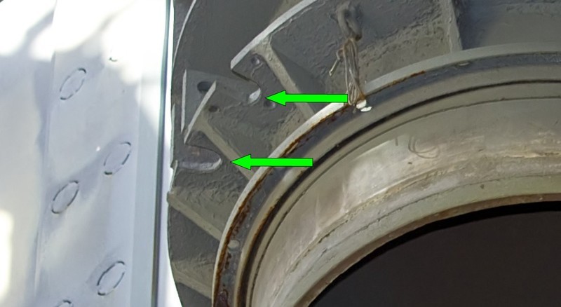
And on closer inspection you can still see these two slots, one directly between the pair of ribs, and one close to it.
But for now enough of preliminary observations. ![]()
However, the flip side of these great close-ups of a friend from the ARC Forums is now the implementing of these details in real components because they shrink drastically after scaling, will be seen as equal. ![]()
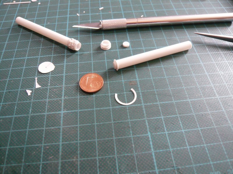
Initially I wanted to take a similar approach in the production of rib pairs as in the previous triangles ribs, for which I have glued two 0,8 mm wide Styrene strips (0,13 mm) again with some overhang with a respective spacer (0,4 mm).
Previously, I had tried to bore this tiny hole (Ø 0,2 mm), which after a few failed attempts still could be realized. ![]()
But then I would have these tiny fins (0,8 mm x 1 mm) to be glued individually what myself appeared illusory considering my sharpest tweezers, because the rib would then have glued rather to my tweezers. ![]() So I had to go without these holes for better or worse which could still be indicated with a fineliner after painting.
So I had to go without these holes for better or worse which could still be indicated with a fineliner after painting. ![]()
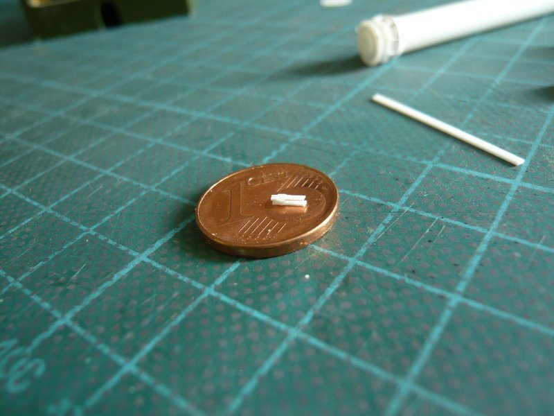
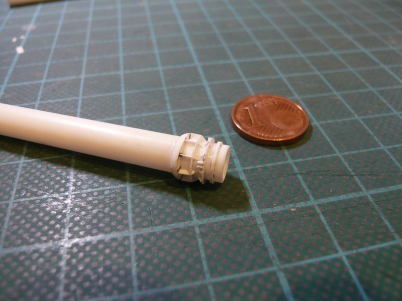
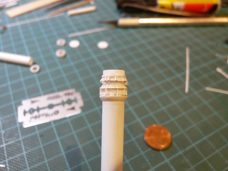
And thus, I then made the three rib pairs without the holes.
After that, I have marked the 120° positions and have sawed the small slots.
After that, I have marked the 120° positions and have sawed the small slots, and above it then glued the first pair of ribs with CA.
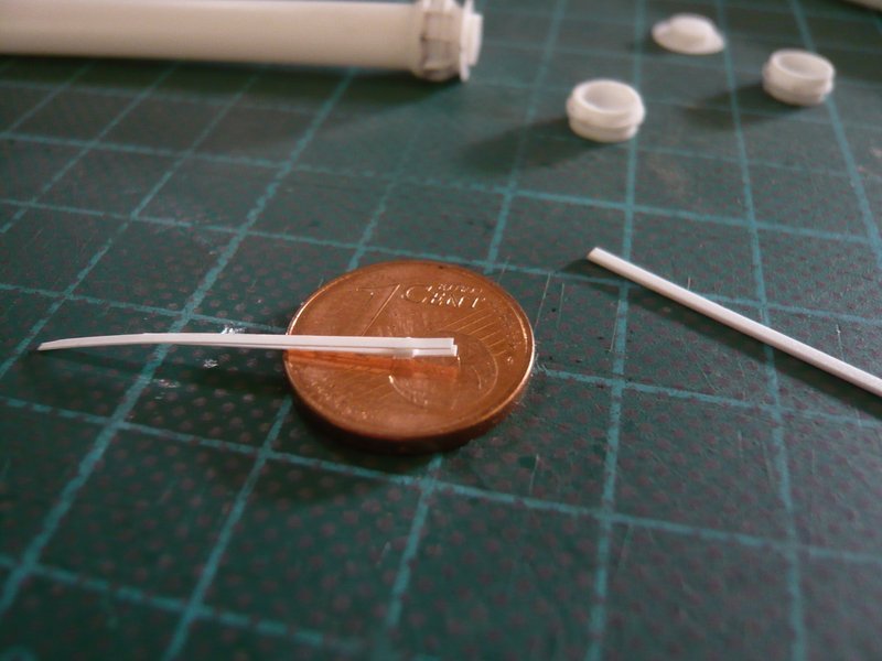
But already during cutting off the overhang with a razor blade both ribs are broken off. ![]() Probably I have not waited long enough, perhaps the blade was canted, or the adhesive bond was still too weak.
Probably I have not waited long enough, perhaps the blade was canted, or the adhesive bond was still too weak.
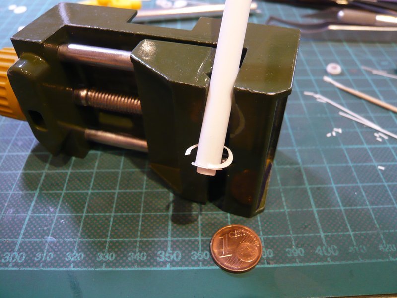
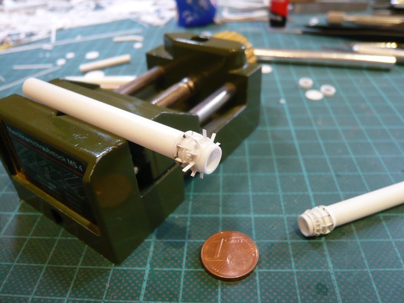
Therefore, I have the following rib pairs after the CA-attachment precautionally still stabilized with MEK. ![]()
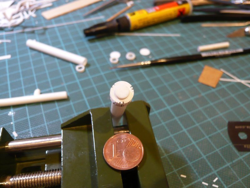
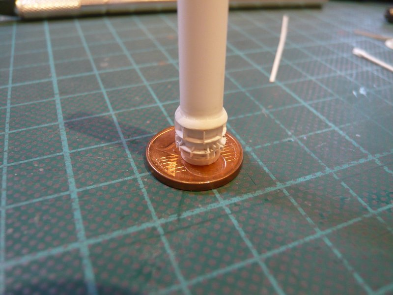
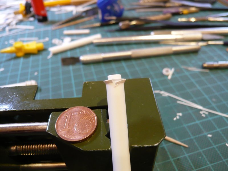
And then I have cut off the overhang of the first couple gently and was glad that everything went well,
and looked not bad. ![]()
And then the other two pairs followed,
which proves that it works indeed so, if somewhat difficult and stressful, what in this size range is truly but no wonder.
And so tomorrow the small triangle-ribs would be on my plan, with whom I fortunately already have some experience, but nevertheless it will probably become a very nice teeming crowd. ![]()
![]()
Very neat looking … Always great looking at these updates.
I see the laser surgery is paying itself off on this project…all those tiny details being added with precision.
![]()
I would need RoboCop eyes just to see these crazy tin stuff ![]()
Thanks John and Mike,
but be smart and don’t do this to yourself. ![]()
However, for handling such tiny parts at very close range, I always use my headset magnifier to fix them exactly. ![]()

![]()
Hello together,
and back again to the tiny ribs, although it went on only a small step today, it should become rather stressful. ![]()
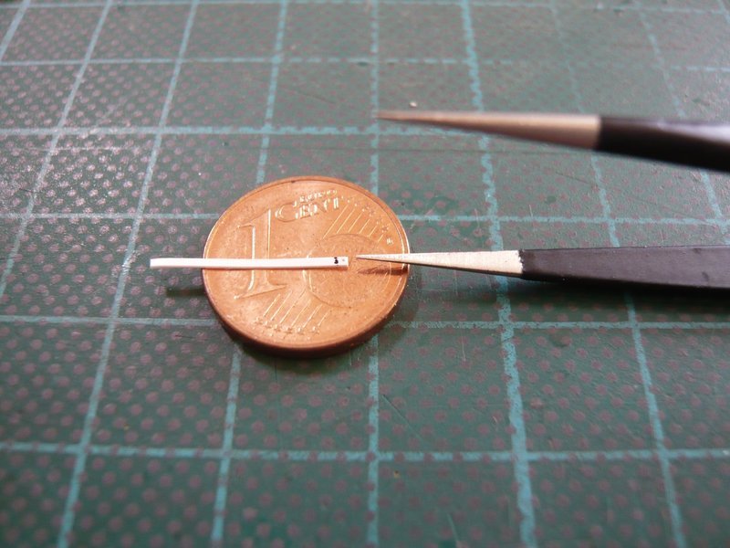
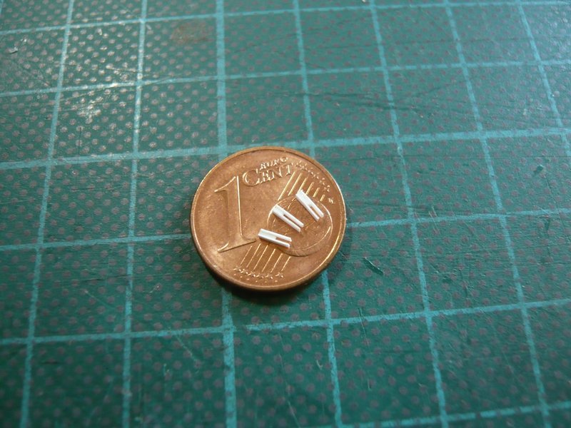
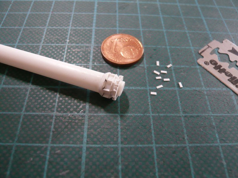
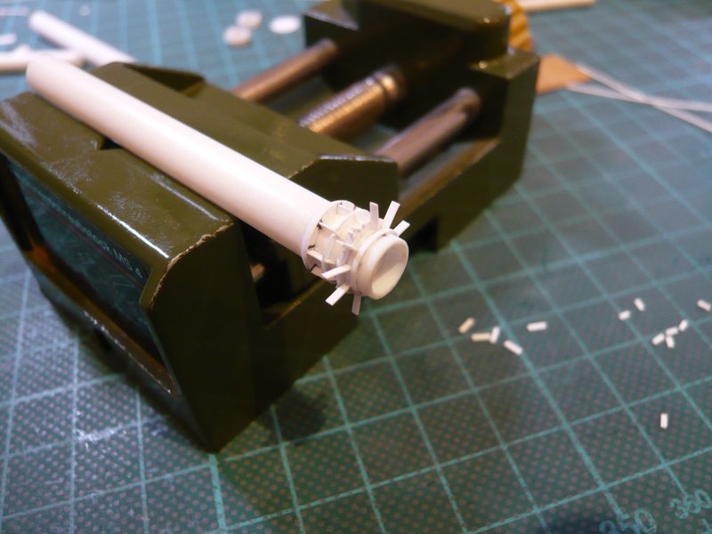
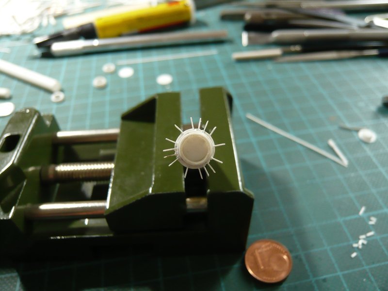
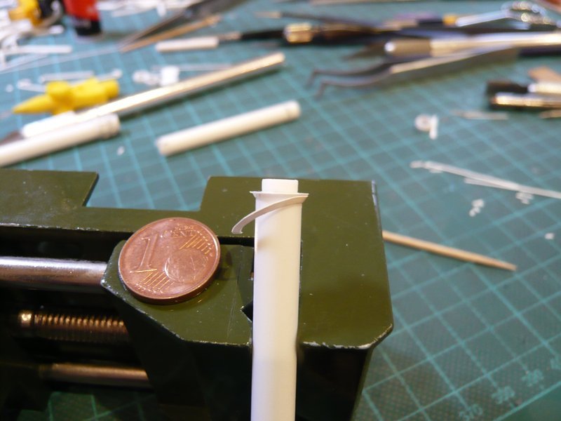
Here are initially the small 3 mm long strips (0,15 mm x 0,8 mm) for the triangular ribs, 24 of which are needed.

Here 9 ribs sit above the ring, each between the rectangular ribs pairs of,
and below there are even a few more, namely15 pieces. ![]() But that was again an undertaking, which has very stressed me.
But that was again an undertaking, which has very stressed me. ![]()
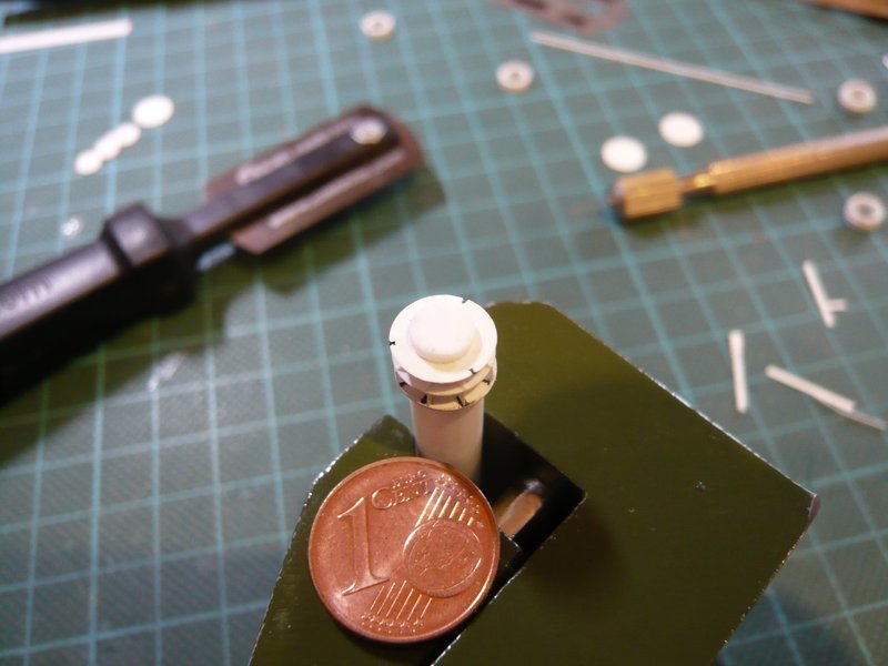
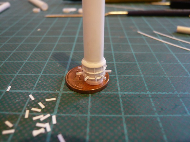
Firstly, the snippets are difficult to keep in the tweezers, then the front ends were carefully dipped in CA and glued, whereby one but immediately has to meet the marked spot. On the other hand some strips also were glued on the tweezers, so it was all in all again a nerve-wracking game of patience. ![]()
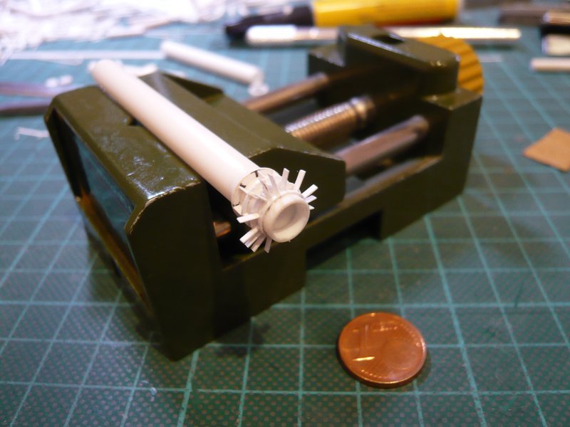
The previous intermediate result certainly looks like this, and conveys already a foretaste of what then awaits me on the underside. ![]()
The overhangs will be cut off tomorrow, and then follow the 15 ribs on the underside of the ring, which certainly should be even more stressful because the already small distances should move together still closer. ![]()
But somehow it will work out, I hope. ![]()
![]()
Hello everybody,
today now follows the last act of the Ribs Festival at the lower ring of the coupling socket. ![]()
First, the upper nine overhangs were cut off, first vertically again, to create more free movement for the 45° cuts,
and then were made very carefully the oblique sections.
Then the still missing three slots were sawed.
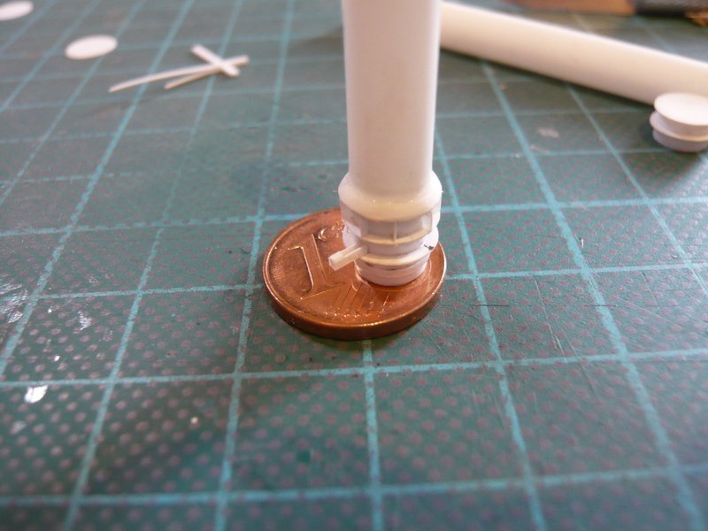
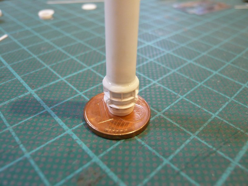
And only now I have glued the lower tube segment with the narrow ring definitively with MEK. ![]()
Then it went onto the underside of the ring, on which now 15 triangular ribs must be placed. ![]() And since in this narrow space it is hardly possible in order to measure tiny distances, the space was divided much more of the optics ago.
And since in this narrow space it is hardly possible in order to measure tiny distances, the space was divided much more of the optics ago.
Therefore, I have initially glued in each case the three ribs in the inter-spaces below the rectangular ribs pairs,
and then in each case the two ribs, which are located below the ribs pairs.
These ribs were then cut off again initially vertically,
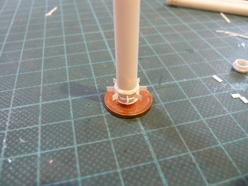
and finally bevelled at a 45° angle, which was truly no bed of roses. ![]()
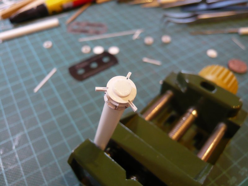
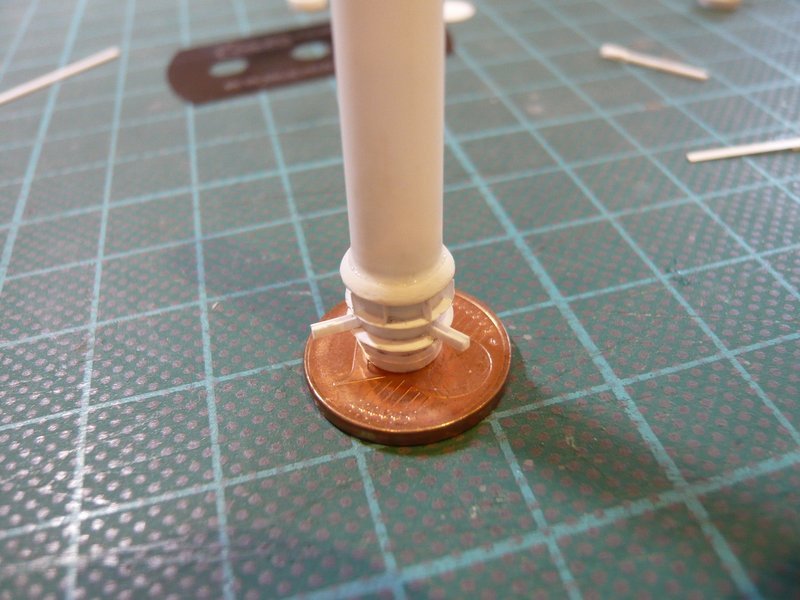
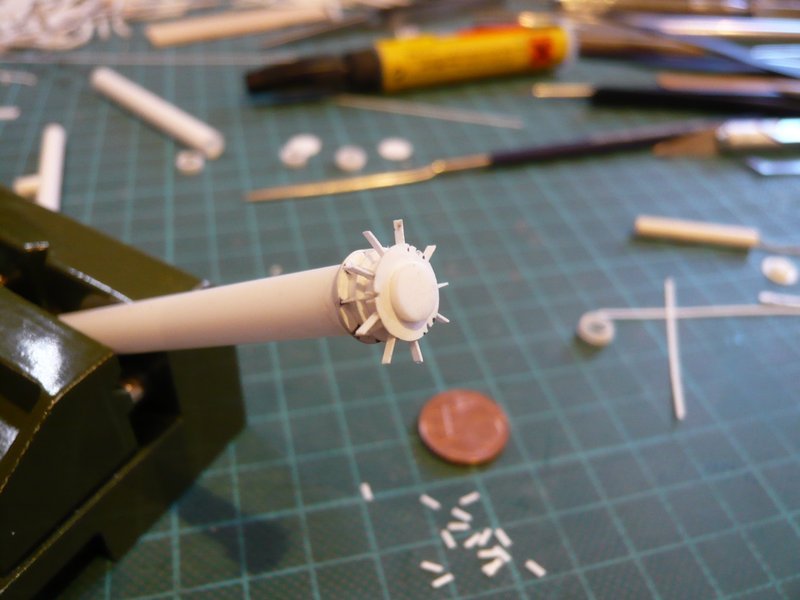
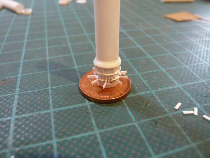
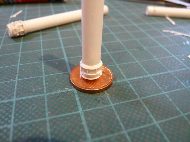
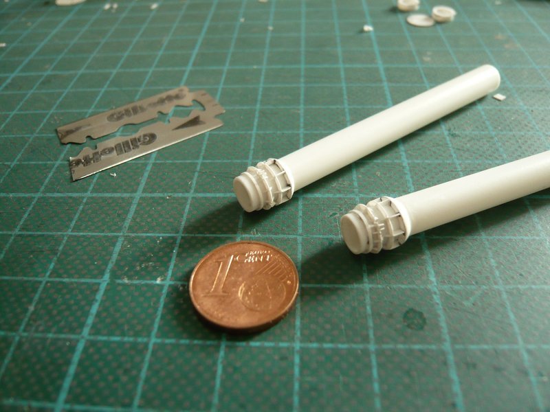
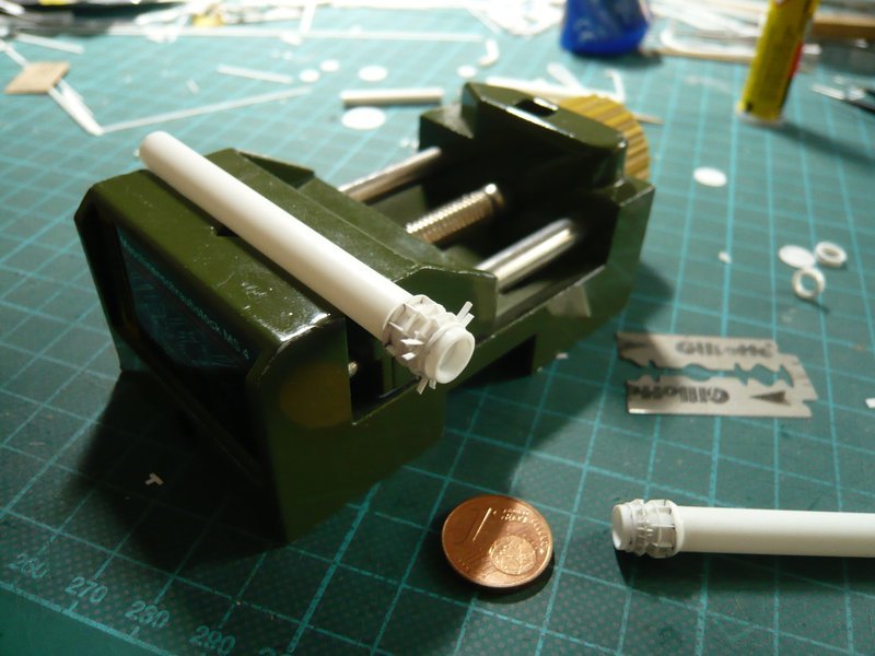
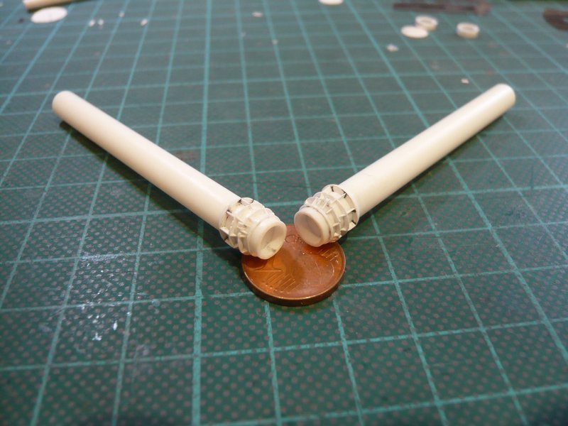
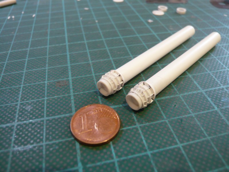
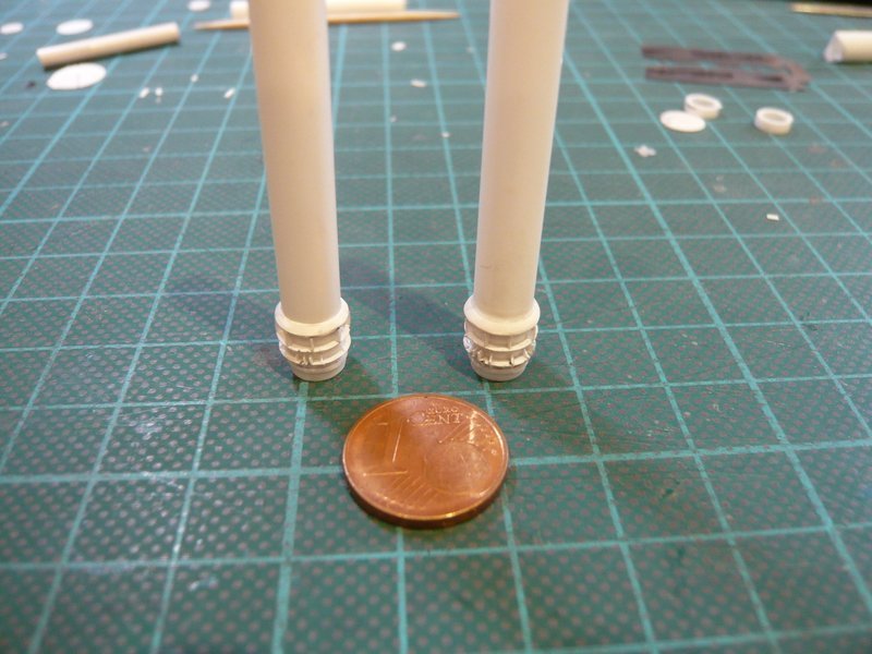
And here, finally, is still the view of the mounting position. ![]()
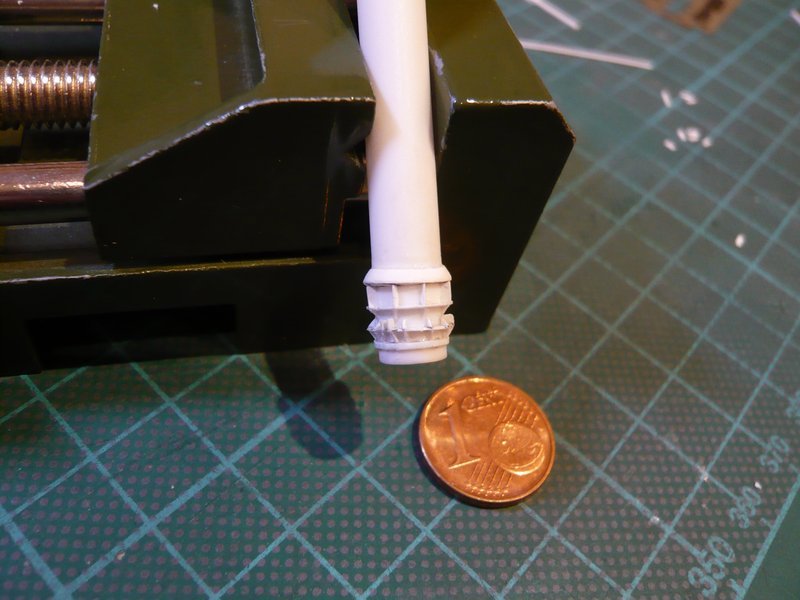
And when one considers that about 60 parts were scratch-built at this pipe, then that is really hardly to believe. ![]()
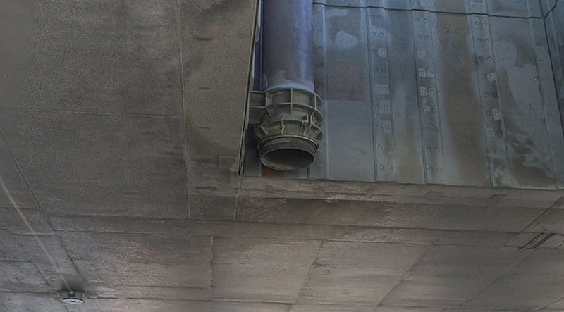
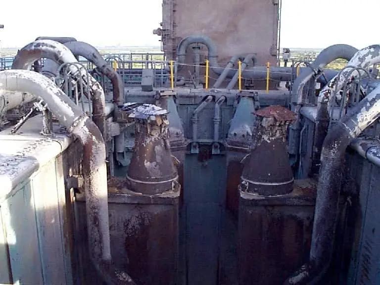
But so it is now almost done, because now only the small support is missing, with which the coupling socket of the pipe is fastened to the inner wall of the SRB chamber, which can be seen in this image.
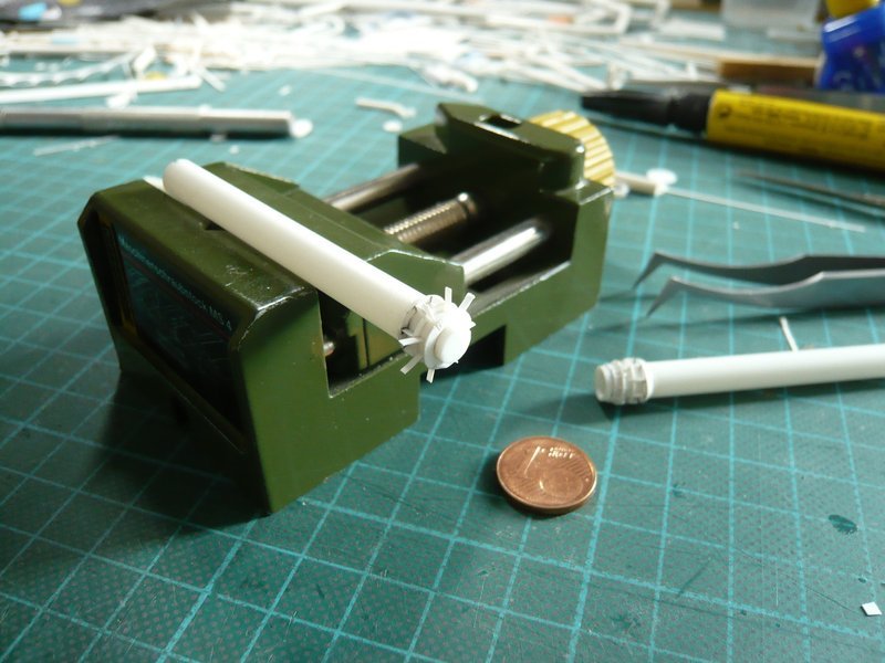
Fortunately, there are only two of these feed pipes, ![]() so I have the whole procedure only to exercise once again, thank God.
so I have the whole procedure only to exercise once again, thank God. ![]()
![]()
Another work of art, amazing work! I recall having to cut 45° angles on thin & tiny Evergreen panels for something, can’t recall what it was – anyway did you do it by eye alone or did you have some template? I remember doing it by eye alone was not as simple as it seemed, no room for error at all.
Thanks Tim for your nice compliment, ![]()
I can rely on my eagle eyes! ![]()
![]()
Someone really must talk to NASA about the complexity of their designs. They clearly don’t understand what a challenge it is for modellers to replicate. ![]()
![]()
Hello everybody,
and thus back to the coupling socket at the other 36’’ inlet pipe. ![]()
This time, however, I did not use a triangular profile for the conical ring (truncated cone) but wanted to try it with the winding-off of the truncated cone, for which I wanted to use a thin PE sheet (0,13 mm). In doing so, I had hoped that the PE ring would let align closer to the pipe than the bulky 1 mm triangular profile. ![]() But for that one needs the winding-off of this part, whose construction however I had to look for initially.
But for that one needs the winding-off of this part, whose construction however I had to look for initially. 
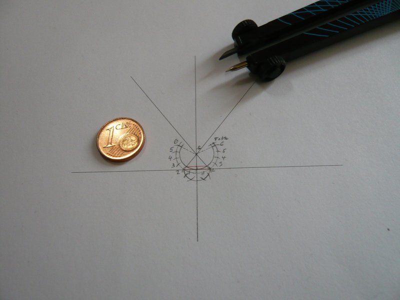
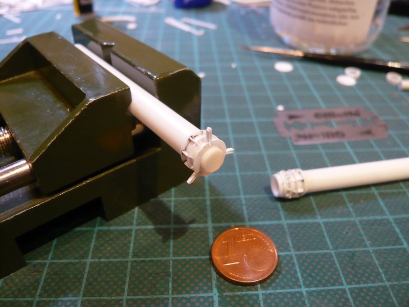
And after I had found a corresponding guidance, I tried out the design on paper on a 1:1 scale. The truncated cone is 1 mm high and the diameters are 6,3 mm and 8,0 mm respectively (see red contour). ![]()
Afterwards, I’ve repeated it on the thin PE-sheet and tried to cut the winding-off with the circular cutter, but because of the small size did not go so easily from the hand. ![]()
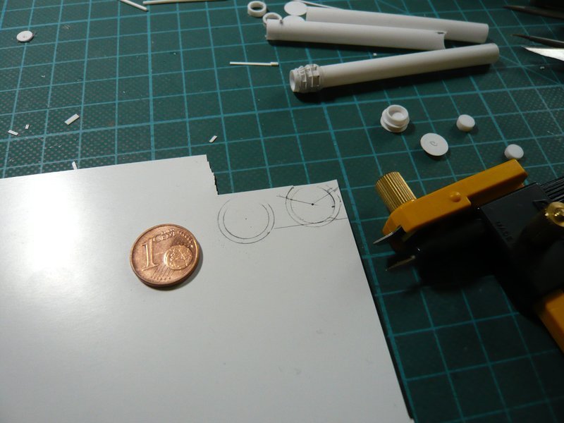
And that was the proud part, the edges of which I then had to smooth something.
After sticking of the first ring segments it was then possible to start with the gradual sticking of the winding-off above the ring,
whereby the beginning was important, which had to be fixed tightly.
And then it went with normal Revell glue in small steps round about.
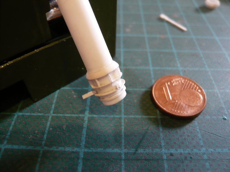
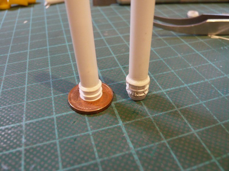
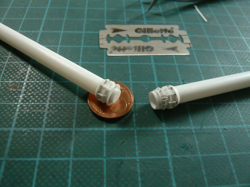
And here is the result, whereby I find that one can already see the difference, because the new ring has leaned up closer to the pipe, and the cone is slightly more flat than the other. ![]()
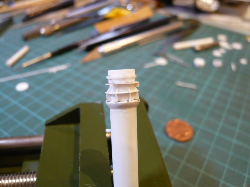
After this, the ribs followed in the usual way, first the eight wider strips between the upper rings,
and then the narrower strips for the underlying triangular ribs,
here after the final circumcision. ![]()
That’s it for today, because now it becomes again a little more stressful. ![]()
![]()
Wow … super update … I wonder what the mean temperature is in that area when the rockets let rip on take off ?? does any damage occur to the fittings ?
Thanks John,
I would have to research the exact temperatures first, but in any case it was incredibly hot around the Blast chambers during liftoff, as you can see in these images,
so the paint crew had to come after every launch to paint all new. ![]()
But even more serious was the impact of the acoustic energy reflected from the MLP during liftoff, which is why after Columbia’s maiden flight (STS-1) the Sound Suppression Water System (SSWS) was installed to protect the Orbiter and its payloads from being damaged. ![]()
![]()
Hello everybody,
today I will now finally complete the connecting piece of the second supply pipe, on which still lacked the rectangular rib pairs and the triangular ribs on the lower ring. ![]()
After the rib pairs over the slots were glued and cut off,
the nine ribs between them were continued in well-known manner. Thereafter, the corresponding ribs sitting below them on the underside of the ring were glued,
and finally bevelled.
And only then did I have glued the remaining six ribs below the rib pairs, which was easier for reasons of space than for the first inlet pipe, where I had first glued all 15 ribs, which made the bevelling quite difficult. ![]()
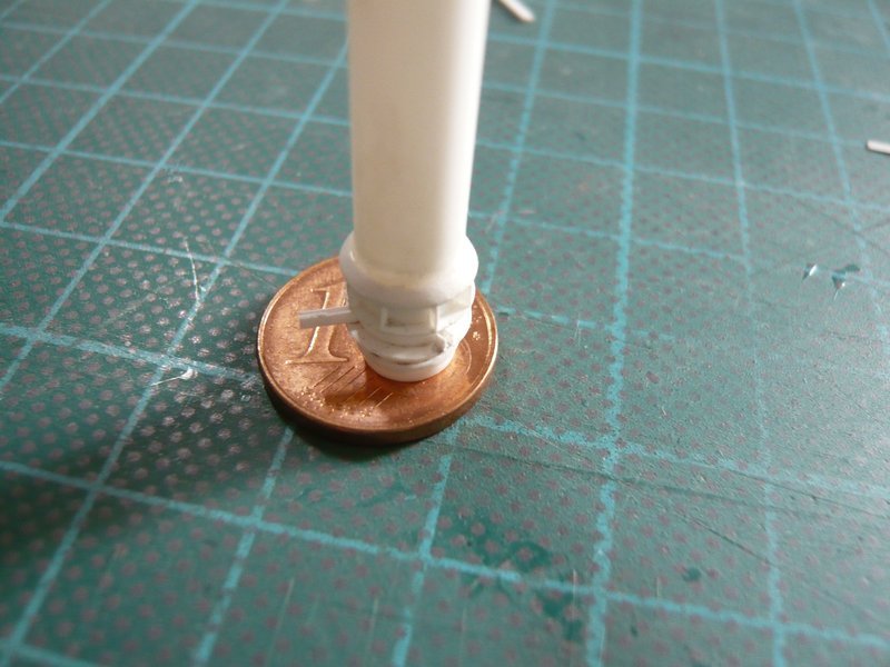
And after the bevelling of the last six ribs, this tricky fiddling was finally done and I’ve felt relieved. ![]()
Therewith all pipes and outlets of the SSWS are finally finished and can be further processed. ![]()
![]()
Yes I too was wondering about the immense forces the plumbing was subjected to at launch. Apart from the temperature & acoustic energy, the sheer force exerted by propelling several hundred tons of Shuttle/boosters off the launch pad would have required some serious mathematics. To prevent those pipes buckling/bursting I can only think they were extremely thick. It boggles my mind to think they only had to worry about re-painting them?!
Hi Tim and hello friends,
the SSWS was extensively tried and tested before the start of the Shuttle program. It was constantly monitored by sensors and it is not just painted after each launch, any damage is of course repaired. ![]()
Therefore here are some interesting information for better understanding.
At the beginning of the Shuttle program, the SSWS consisted only of these 6 Rainbirds, here during a test with the Enterprise (1979).
The same system was used during the first launch of STS-1 (1981).
The sound pressure during liftoff was greater than anticipated. In addition to the partial damage on the MLP deck,

a thorough inspection revealed that around 1% of the Columbia’s heat shield tiles had been damaged during the launch. ![]()
That is why the SSWS was modified and improved before the second mission STS-2, ![]() both by the Water bags suspended in the Blast chambers,
both by the Water bags suspended in the Blast chambers,

and by the system of the Ring lines with the outlets surrounding them, what looked after liftoff like this.

For anyone interested, here is an impressive video of a SSWS test. ![]()

And then I came across this impressive video,

in which the effect of the SSWS is demonstrated in a model test. You will be amazed. ![]()
![]()
You don’t seem very enthusiastic, so I can only save myself such extras in the future. ![]()
![]()
Give it time Manfred, you only posted it around 24 hours ago. Very interesting videos, now I understand reverse-bubbles ![]()
Love the vortex cannon. - “I gotta get me one of them!” ![]()
The sound to heat conversion is fascinating. Thanks for the post.
Cheers,
Colin
Thanks Tim and Colin for your interest.
I know that the circle of people really interested here in the forum is very small, compared to other forums in which I’m also posting.
About 50 hits within a week in KitMaker, in other forums several hundred per day to day. This is just a sober comparison, not a judgment.
That’s why the SSWS post with the two rare videos was a special bonus for freaks, which cost me about half an hour just to find these unique videos and old photos in my database. When I saw these videos for the first time years ago, I was thrilled.
Have a great weekend. ![]()
![]()