Space Shuttle Launch Complex 39A with Challenger STS-6 (1:144)

Hello everybody,

and it goes on with the new lining of the SSME Blast chamber, which was to be seen. In this case, it strikes the experts immediately that the template from D. Maier’s Paper kit has no step-shaped shoulder, but it is present in the original.

First, I detached the struts and already started sanding the glue on the backs.

For that I had initially used Evergreen profiles 1,0 x 1,0 mm. However, this thickness appears to me to be somewhat oversized from today’s perspective and in comparison with more recent original images, given the proportions in the chamber.

Came across it during the sighting of my photo collection in preparation for the construction of the SSWS. Meanwhile, there are in particular from last Shuttle missions awesome NASA panoramas with high resolution, on which one can do great detail studies.

And here is one image of them, where one can also see the SSME chamber very well from below.

Unfortunately, NASA has changed the Panorama URLs so the link no longer works and I can only show a close-up.

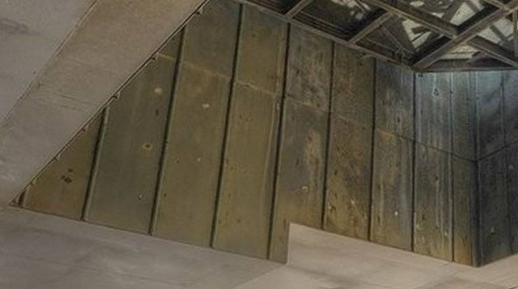
In this image I have determined the thickness of the struts using the grid distance compared to the template, which should be not 1,0 mm but only approx. 0,6 mm. Now this is not a great difference, but it does come much closer to the original and thus fits better by its proportions into the image.

And if you look closer, you will also recognize that these are not prismatic profiles but rather thin tubes.

Here is another working Panorama view from the SSME Blast chamber, where one can see the thin tubes on the walls.

3D-rotatable view of this area at nasatech

Source: NASA

Accordingly, I have placed some profiles for comparison on the template.

In my opinion, Ø 0,64 mm rods would probably fit best, but maybe it will be a bit more difficult to glue them clean than the square profiles, what do you think?

And the struts have to be painted anyway new.

4 Likes

This is a fascinating contest – Man(fred) vs. Model – it looks like you’re definitely going to win on points, if not a TKO! Great project, narrative and photography, bravo.

To my eyes the 0.5 would look better – it’s a tiny difference to the 0.64 I know, but sometimes with elements like this I’ve found it’s better to be slightly under-scale than over-scale. Even though I think 0.5 looks more at scale. Maybe paint the two options and lay them down again to see if that helps a decision? As you said it may be easier to glue the square-section 0.5 too.

Thanks Tim for your enthusiasm for my work.

Yep, sometimes I’m feeling like on a battlefield during these emergency surgeries indeed and I’m glad when I’ve repaired all the damage. up0373121

BTW, I agree with you that these are only minimal differences, but in the end I had to make a choice. And often a bit of shadow is still in play too. up0405771

1 Like

Hi folks,

but I had initially especially concerned about sticking this thin profiles. But a test gluing with a Ø 0,64 mm rod by using CA and acupuncture needle along a line has certainly worked, so I’ll take these profiles. up0455181 Of these I also have sufficient lengths, because one needs after all approximately 1,5 m, which is hard to believe.

Now I just have to think about how I best can paint the strips. From the airbrush gun thin things are almost blown away, and one anyway sprays more color next to it, as at the profiles.

With the brush by hand on a pad that’s for sure similar tricky and will probably not uniform. That’s why I got the idea, to stick the five profiles side by side on a frame of cardboard and then full power with the gun over it. That would actually go, I guess.

And I then tried the same times. Here are the 0,64 mm rods,

and here’s my brilliant strip holder.

So the first passage with the gun is across the stage, and the holder has actually proven.

That’s it for the moment, see you soon! up0405771

1 Like

Hello friends,

if you are ready, then let’s go on.

But before I continue to do with the lining of the SSME hole, I again checked the position of the Blast Shield under which, in contrast to the SRB Blast Shields a lot of water nozzles of the SSWS are around.

In it are now the TSM’s after the widening of the shaft at its final location directly next to the hole, so that I can now prepare also the respective Blast Shield.

In this connection, but is still following new facts. In the analysis of my SSWS panoramic images I’ve even noticed some details of construction that I have been so never known and which are not included in David Maier’s Paper Kit.

But as one can see in the picture here, there are at the forward end of the SRB holes in each case inclined transitions in the Blast Shields to the significantly higher SSME Blast Shield, which should be about twice as high in my estimation.

3D-rotatable view of this area at nasatech

Source: nasatech.net

In the Paper Kit the heights of both Blast Shields were of equal size what I had previously thought as right. And this difference but one should actually already consider when looking at it exactly, right?

Well, that could be on the occasion also quite corrected or adapted even without major problems, although the difference with about 1 mm (1:144) is actually minimal. Nevertheless, I will think about. icon_hmm

And so now get back to the lining of the SSME hole again. On closer inspection of the image below one can see the following fundamental difference between the SSWS systems of SSME and SRB exhaust holes. As briefly mentioned (red marking) under the SSME Blast Shield around water nozzles are arranged in rows, how to follow very nicely on the panoramic image.

3D-rotatable view of this area at nasatech

Source: nasatech.net

In contrast, the blast shields of both SRB holes around have no water nozzles but only openings for the outflow of the water ejected by the Rainbirds at the start, as one can see in the picture, while the water masses are here pumped in each case through the large outlets.

3D-rotatable view of this area at nasatech

Source: nasatech.net

Since the water nozzles are not taken into account in the lining of the SSME shaft in Maier’s kit, I’ve tried, if they can not be visually indicated at least, especially since they are really too tiny in my scale for scratch-building.

To help me later gluing the hole lining something that I have this first separated,

especially since the thin rods also have to be glued and so the individual walls are easier to handle.

After that, I’ve copied the red marked nozzle row from the the upper image,

and duplicated the Nozzle 51 several times with Paint Shop Pro and arranged in a row.

Since the true to scale print of this row (2 mm), but produced only a dark stripe, I still have regulated a bit on the sharpness as well as the contrast and brightness.

And in this print were then quite still details to realize how you can see here.

And the tentative location of the nozzle row on the lining with a round profile and under the Blast Shield cover also shows a good color match.

And now it went to the substructure of the Blast Shields, which is again made of Balsa (2 mm).

As far as for now, thank you for watching. up0405771

1 Like

Hi friends,

due to the widening of the SSME exhaust hole I have meantime decided to take into account the different heights of the SRB and SSME Blast Shields, since the connecting dimensions anyway no longer have agreed.

As a result, I have removed the previous SRB Blast Shields again in order to install the stepwise transitions to the SSME Blast Shield, which I had already shown in this image.

3D-rotatable view of this area at nasatech

Source: nasatech.net

That’s why I have separated the template from the Paper Kit precisely at this transition at the front end of the SRB holes and made corresponding templates for the substructures. Since their size deviates anything in both length and width from the 1:144 templates I need to divide and fit the templates.

While the two rear parts of the Blast Shield become of cardboard, about 1 mm high,

the connecting part of Balsa gets about twice the height and reaches behind the TSMs.

And in front of the TSM’s closes the front part of the Blast Shield, whose Balsa substructure I have already done so.

Bye for now. up0405771

Let’s continue with the next step in which I have transcribed the templates for the substructures of the SRB Blast Shields on 1 mm cardboard and for the SSME Blast Shield on 2 mm Balsa. This produced the step-like transition at the front end of the SRB holes, which is still slanted.

Granted, the difference in height of 1 mm is relatively low, but significantly, and thus corresponds approximately to the real state.

And the two TSMs also fit nicely between.

Now the casings are glued on these substructures and so wrapped.

And to finish the top covers are glued then on the casings.

BTW, at the same time I will still look after the pipes of the SSWS, which are running under the SRB Blast Shields into the SSME hole (green arrows) and into the SRB holes (blue arrows), in order to provide suitable holes for these pipes in the substructures before gluing.

In this image one can see the different pipes,


Source: NASA

and next time I will show these pipes in some panoramic images in more detail. up0405771

2 Likes

Hello everybody,

as was seen in the last image already, the SSWS consists not only of the thick 24’’ pipes, which are nevertheless about 61 cm in diameter, but also from various thinner lines which are bizarrely bent and partially narrowed.

These are first these blue marked 6’’ pipes (Ø 15 cm) which branch from the thick pipes behind the TSM’s,

3D-rotatable view of this area at nasatech

Source: nasatech.net

then pass under the Blast Shield and end in vents at the front end of SRB holes between the SRB supports.


Source: capcomespace.net

Please do not scare now about the seemingly “scruffy” state, but so the holes looked every time after a normal launch, but they were sandblasted before the next start and then freshly painted.

And so here are the other pipe lines branching off from the thick pipes between the SRBs and also pass through under the Blast Shield forward into the SSME hole,

3D-rotatable view of this area at nasatech

Source: nasatech.net

and combine there in a central part on which a row of outflow vent nozzles is sitting.


Source: NASA

And these pipes interested now only in order to prepare the corresponding inlet and outlet openings in the raised substructure of the Blast Shields.

While the “blue” pipes have to be about 1 mm in diameter, the “green” tubes are slightly thicker with about 1,3 mm diameter. And the tiny nozzles should then be approximately 0,5 mm in diameter, which just seems to be feasible.

As you can see in this picture, the “green” pipes directly disappear in the corners of the raised Blast Shield and run underneath forwards to the SSME hole.

3D-rotatable view of this area at nasatech

Source: nasatech.net

After I had estimated the required dimensions, I could mark the location of the openings for the pipes.

As one can see, one has first to do some considerations before the right start. up0405771

Adding a link (use the icon with two connected chain links) works
Using the img-brackets also work (tried with random image from imageshack).
Pasting the adress of the image worked with the Corvette but not the images from the post above,
this means that imageshack does not have a total aversion against hot linking.

I hope you can follow my linked images with URLs from other websites.

You may come across links in my NSF thread that I link to from time to time, which show error messages. This is because NASA made changes to their URLs some time ago, which I’m trying to correct them here step by step by replacing them with working nasatech.net links. up0405771

1 Like

Hi friends,

as already mentioned, I had to split the coverings before sticking and to adapt to the modified dimensions of my SRB/SSME holes.

At subsequent gluing of the substructure must make sure that the coverings sit immediately to the right place. Therefore I have drawn the contours on the backs and the rabbets easily scratched, so that the edges become clean. Only then I glued the substructures, let it dry, and then glued the rabbets on the bottom.

That was already half the battle.

And just the raised Balsa parts were wrapped for the SSME hole.

The middle part between the SRB holes I have glued separately, the reason why I still show from the back. The openings for the local line with the vent nozzles, I also have broken through, as long as the marks are still visible.

Since on the back of the SSME Blast Shield in the middle part there are no vent nozzles, I have indicated there the open passageways.

And thus the substructures are now completely covered,

and are just waiting for the top covers.

These I have also to split and adapt again before sticking, and before that I have to devise a solution to the oblique transitions between the blast shields.

My first attempt with a handle-filed wedge of balsa was a bit of fumbling and has not convinced me.

But I have another idea. up0405771

2 Likes

I think that small Evergreen profiles should be better suited for the wedges.

For this now I have selected a strip of 3,2 x 0,5 mm and a square profile of 0,5 x 0,5 mm as a base, what exactly is the height of the transition.

And on that occasion, I now wanted to try out a new adhesive recommended by a friend of mine as a secret weapon for glueing small parts, on which he swears.

It is MEK (Methylethylketone) or also short Butanone. MEK as acetone is a good solvent for a variety of plastics, resins and varnishes. The stuff is thinner than the known Revell adhesive and can therefore be easily applied with a brush, but beware, the brush must be made of natural hair, e.g. Red Sable, otherwise it is only to be used once and never again.

The advantage of this adhesive is that you only need to position the parts and the adhesive is applied with a brush stroke at the joint, which feeds into the gap. Then just hold still for a short time, and the contact is done.

And just as easy has worked, the strip I have applied to a ruler, placed the small profiles and fixed with tweezers, and then drawn with a brush MEK at the joint along, that’s it.

And that goes in the twinkling of an eye.

This secret weapon so I can only recommend it. up0405771

2 Likes

A less aggressive and less harmful solvent but equally potent as “glue” is
ethyl acetate (major component in acetone free nail polish remover)

I’m totally satisfied with MEK, mainly because you only need minimal amounts for wetting the contact points with the brush. And the bottle I’m using around for several years. up0405771

1 Like

Hello everybody,

today I carried out a few experiments to test the feasibility of the following detailed solution.

As shown already, there are on the back wall of the SSME hole this SSWS piping with the six vent nozzles.
3D-rotatable view of this area at nasatech

Source: nasatech.net

The dimensions for this I had already estimated, after which the pipe should have about 1,3 mm in diameter and the nozzles then about 0,5 mm in diameter, which I instinctively just appeared to be feasible. And I wanted to check today.

And as always with such things a scale drawing is very helpful, and how you can already see that this part but is relatively small.

And these are my first two prototypes of the pipe (Ø 1,4 mm), which should be about 30 mm long. Since the first pattern has unfortunately yet become slightly shorter and did not fit into the openings, the second experiment was (front) then more successful.

And as you can see here, the pipe fits quite well into the openings of the Blast Shield.

And so now to the nozzles of 0,5 mm rod that truly are, however, some small check marks which should be only about 1,5 mm long. Can bend itself yet, but the separation and handling is then even more marginal.

That reminds me sticking the nozzle is problematic in terms of durability of the contact point due to the tiny cross-section, I first experimented with my dummy and carefully drilled a hole with a diameter of 0,5 mm and the nozzle being only inserted. Now this is indeed a bit difficult, but doable.

And this exercise should work just as well in the remaining five nozzles, I hope so.

For comparison, I will now try another gluing with MEK and am curious as to whether or how well that will hold.

1 Like

Next I wanted to finish the reconstruction of the Blast Shields finally, for it the top covers were now still to glue to the substructures.

Unfortunately I could not glue them in this form, because I had modified the geometry of all three holes. So that’s why just had to split as the covers for the substructures.

But this was not a major problem and done by the cutter, and then the SRB Blast Shields with their inclined transitions and the beginning of the Orbiter Blast Shield were covered up to the TSM’s.

The front part of the Orbiter Blast Shield was relatively easy and just needed something be cut in front of the TSM’s because the width so now is corresponding with the 1:144 dimension.

And finally, the TSM’s were still tentatively put.

And so I can now continue the lining of the SSME hole, what’s next turn. up0405771

2 Likes

Hello everybody,

now the lining of the SSME Blast chamber follows, and here we go to the back wall. First I glued at the top the strip with the indicated water nozzles, which I have reinforced something so that it matches as flush as possible with the lower edge of the Blast Shield coverage.

Then the rods (Ø 0,6 mm) were glued, first time only at the top, because the dabbing of CA with the acupuncture needle over the full length can not be done.

And then it went step by step to down, which took some time because I had to aim accurately.

But by and by I had the hang of it, and it went forward.

And so the back wall was then done ever,

and could be glued after a few tests into the hole. This has worked quite well so far, and also the small pipe fits perfectly into the holes provided. Only missing the six nozzles.

And with these nozzles I’ve tested a bit more now. First, I’ve still tried the blunt bonding of a thin profile (Ø 0,5 mm) with MEK, so this time without pre-drilling, but only once placed a stick and then painted with MEK.

Well, that part is first stuck and also holds a light touch from.

But due to the minimal cross-section the contact of course does not hold of a burden and broke off with the first bending. Accordingly, that’s no usable solution for these nozzle row, and so I will have to continue to pre drill.

Well, but now I need the rest of the nozzle, and for that I have ever tried some bending variants. This is possible both in the tweezers, although it is not so easy to get added at the first attempt the short arc, because there are some broken.

That’s why I afterwards used a thin brass tube as bending aid and then cut the nozzle to the required size. In this variant, there is a bit more waste, but the bending is endured over the greater length but obviously better and there have been no breakthroughs.

And here are provisionally inserted into the bores of the six nozzles. Although this already looks not bad, but is still not optimal. Firstly, the holes are not in a row and the last right distance is too great, and the other, the nozzles are still standing out a little too far, so what is correct yet.

That’s why I put the piece aside and went on with the left side wall of the lining.

For the gluing of the rods I’ve also been thinking a different solution, since my CA dabbing with the acupuncture needle in the long run but was too stressful. That’s why I used this time a Pattex-Special glue PXSM1. It is suitable for plastics, e.g. Polystyrene, ABS, Acrylic, Polycarbonate, hard PVC, etc., such as for wood and textiles and has a long dosing needle for precise dosage.

With this dosing needle (Ø 0,8 mm) I have placed each on a separate sheet of paper a thin line of glue, dipped the profile lengthwise and then glued to the lining, and the process is much easier and especially faster than before.

And so now was the left side of the hole also be covered,

and the remaining two sides can follow. up0405771

1 Like

Hi friends,

and thus to the linings of the remaining two sides, which are constructed in a manner analogous to the first two.

The gluing of the linings had to be carried out with caution and without great position corrections to not detach the profiles again.

Here, first the front wall,

and here the right side wall.

And so the state before the rebuild had finally again reached,

so here’s an interesting comparison, how the SSME hole looked before the emergency surgery.

I believe the images speak for themselves and mine that the effort was worth it, because the thinner rods correspond to the original but much more and even better with the TSM’s.

And in order to complete this reconstruction chapter worthy, here are a few pictures with the shuttle stack,

before it continues with the SSWS. up0405771

2 Likes

After reconstructing and re-lining of the SSME exhaust hole a small detail of the SRB Blast Shields is missing, namely the posterior transition to the Blast deck, which can be seen in this linked panorama image.

3D-rotatable view of this area at nasatech

Source: nasatech.net

As can be seen in more detail on the panoramic image, the transition behind the SRB chambers is covered by metal strips that are overlapped at the front edge of double fold-strips which are bolted to the Blast Shields. And this covering strips I wanted to at least hint at something, only a small detail, but it’s a real and closer to the original.

Thus, the transition looked previously,

and these are the strips of paper for it with the details indicated.

And here the strips are “screwed” and the transitions now complete.

Next, it then goes on to the tube with the nozzles in the SSME blast chamber, I’ve changed something. up0405771

3 Likes

And so it went on.

Since my first two prototypes of the rear SSWS tube in the SSME chamber with the six vent nozzles were not really been successful, I’ve made a few thoughts before the third test in order to come to a more practical and better solution.

This time I actually wanted to use copper wire (Ø 0,5 mm) for the nozzles, because one can bend it relatively easily and accurately and the rounding remains but plastic profiles usually tend to bend back, something you need to consider.

But the mounting of these copper nozzle is not without problems, since one must again stick with CA this pairing and the seat therefore should right the first time. However, as already inserting these tiny kringle in the small holes is quite cruelty, I’ve discarded this method then again and stayed in Styrene and MEK. With this method, one can calmly stuck in the nozzle into the holes and fix the seat even before the MEK is painted for bonding to the junction.

In order to compensate for the subsequent widening of the nozzles after bending better, I have initially forced into this tight corset of three rulers,

and thus can control and regulate the widening better.

And so now to the holes for the nozzles. Since the position of the holes was too uneven in the first experiments, I have been thinking this mounting bracket of balsa slats as a courtesy to further handling , which has already proven to be a suitable stop when marking and drilling the holes.

The nozzles I first consciously sized bit longer in order to put them so easily into the bores and still be able to align. Only then I wanted it cut to a uniform length.

Here, the nozzles are already stuck into the holes but not glued.

And now followed the next step in the mounting bracket. To set uniform distances (about 1 mm) above the tube I have put a fitting aluminum angle profile under,

fitted the protruding ends with a steel profile and aligned again. And only now I gently applied the MEK with a brush.

Then I’ve marked the final length of the nozzle row,

and cut off the ends on a steel ruler with the cutter.

And this is now the result with which I am finally satisfied.

And also the seat of the tube on the rear wall is correctly so that it now only needs to be painted.

That’s it for today, see you soon. up0405771

1 Like