That looks like what Wagner would have called a Gutterdummyring… ![]()
I’m so sorry ![]()
![]()
That looks like what Wagner would have called a Gutterdummyring… ![]()
I’m so sorry ![]()
![]()
Hello everybody,
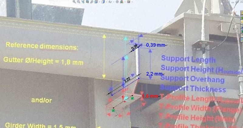
and here are the first SolidWorks Shots from my friend Joe. ![]()
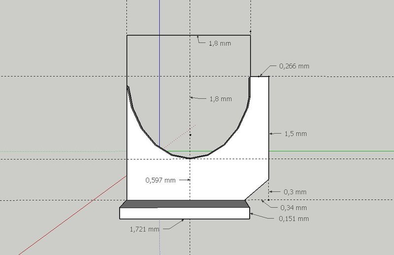
This was his first Front View, based on the diameter of the gutter (10’'=254 mm), which is why all measurements are given in Inch which I converted in 1:144 (Ø gutter 1,8 mm).
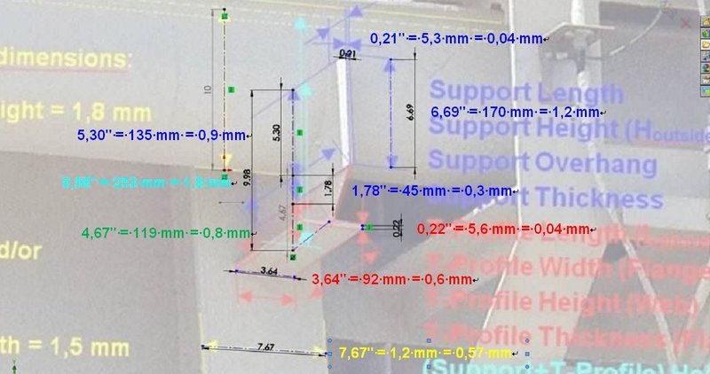
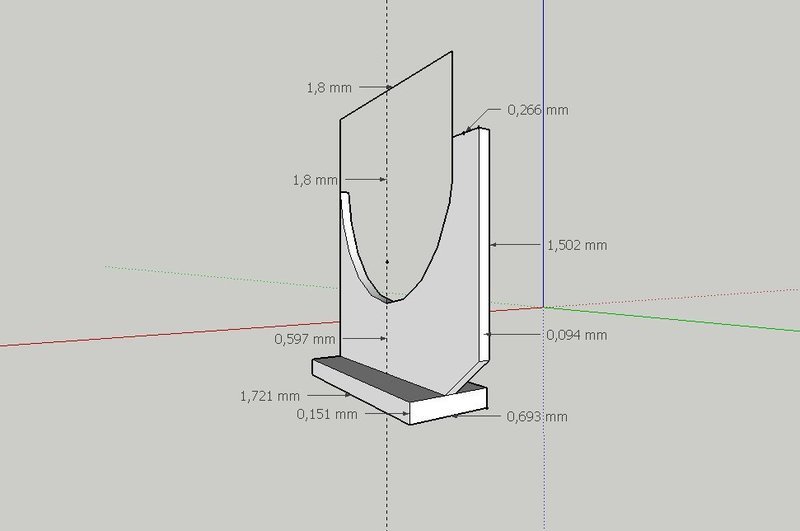
The depths are given in a Side Viewr, based on the depth of the girder (1,5 mm), which also seems to be problematic in SolidWorks due to the extreme skewed perspektive of the girder and support and provides oversized values as one can see. 
Thereupon I had sent him my drawing, which was obviously helpful in the adjustment,
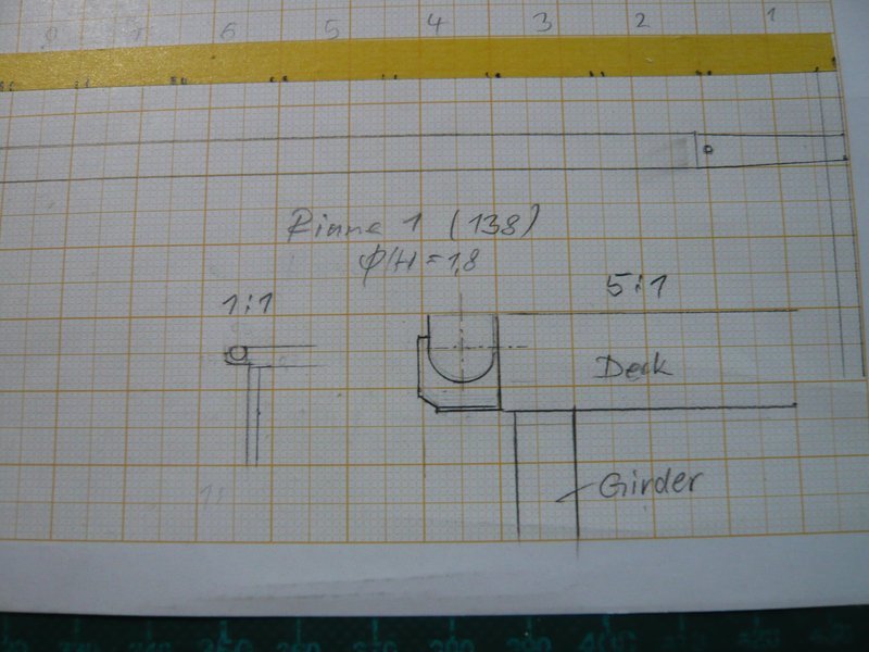
from which this side view with mm values resulted, which looks already more realistic. 
Accordingly, it is obviously important to consider whether it concerns to values of widths and heights or depths, what I have not yet taken into account so consistently so far, but will do so in the future. ![]()
![]()
Hello everybody,
but it does not have to be the Super CAD software SolidWorks, which I do not have and which is also very expensive.
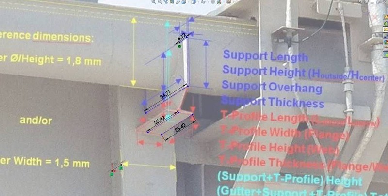
A friend in the Raumcon forum (Hugo) has done this with the comparatively simple program Sketchup and comes to quite acceptable results and is therfore suitable for such scale measurements.
His measurements were recorded in one of his pictures, and the values estimated by me are written in brackets behind, which partly agrees quite well. ![]()

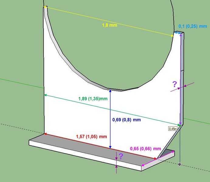
The greatest differences between our measurements occur in the two encircled values,

which is probably due to the fact that my lower values are falsified too much in the picture due to the extreme slant of the support, which is evidently better managed by Sketchup.
And since this 3D software has interested me anyway and would offer itself for my constant elaborate scaling, I have downloaded the free version
Sketchup MAKE and have tried it the same time. ![]()
But all the beginning is hard and a lot is new and unfamiliar, which is why it took me a while until I have become acquainted with the special features of the Sketchup/3D construction step by step, because my 3D imagination still had to be trained. 
But by Learning by Doing I am at least familiar with the basic functions and most important tools. ![]() Only the adjustment with the photos I have not yet succeeded so far, which obviously takes a little getting used to.
Only the adjustment with the photos I have not yet succeeded so far, which obviously takes a little getting used to. ![]()
Thus, e.g. even the Tape measure function has so their pitfalls, since the measuring result is always only briefly shown, but then disappears and one must measure again. ![]() Therefore, one always has to make a separate screenshot, what surprised me at first.
Therefore, one always has to make a separate screenshot, what surprised me at first.
Then I have found out that one can help himself with Text markers, which is not the the answer to everything, but still works. ![]()
Finally, I then have stopped my training and simply started the construction, free according to the principle Trial & Error. ![]()
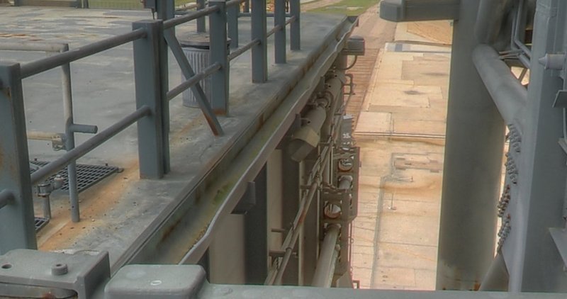
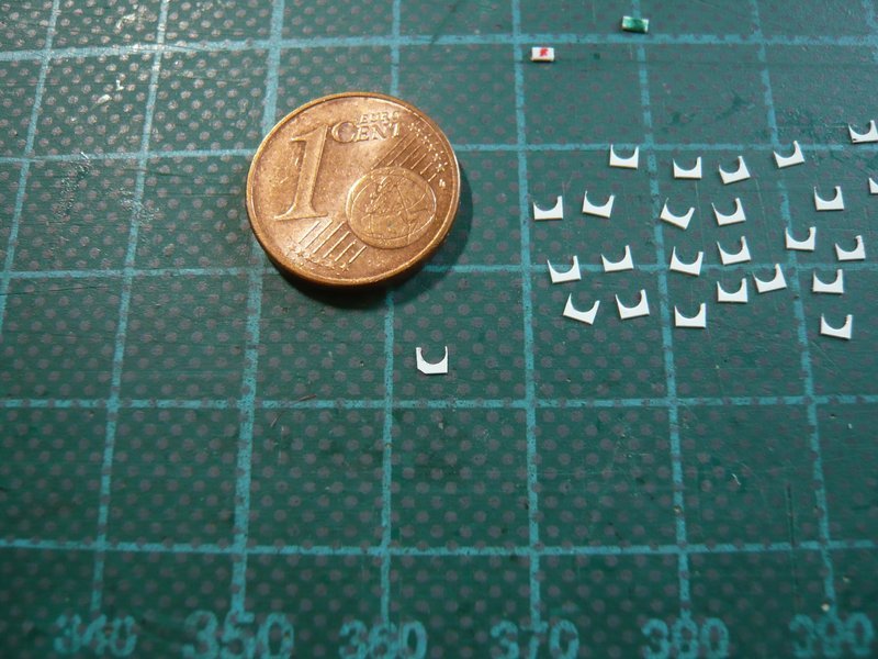
These two pictures show the results of my first experiments, whereby it is important for the later installation of the support that the height of the gutter is taken into account and the lateral edges are correspondingly lengthened, whereby these MLP gutters differ from the usually used roof gutters. 
As one can see, however, the rounding of the gutter by means of a three-point arc has not yet succeeded in an optimal way, and after a closer look at the optics some dimensions appeared to me also in need of improvement, e.g. the slightly too long 1,5 mm front edge. ![]()
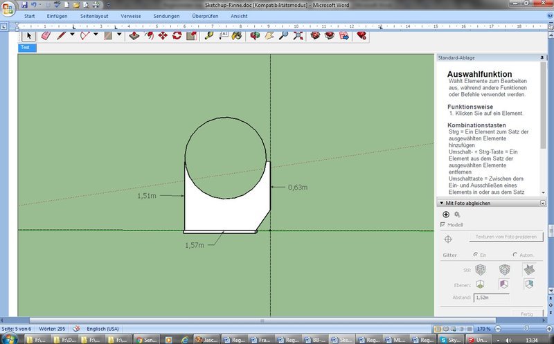
That is why in my next construction I have drawn the rounding of the gutter by means of a circle and the dimensions slightly modified, which looks much better. ![]()
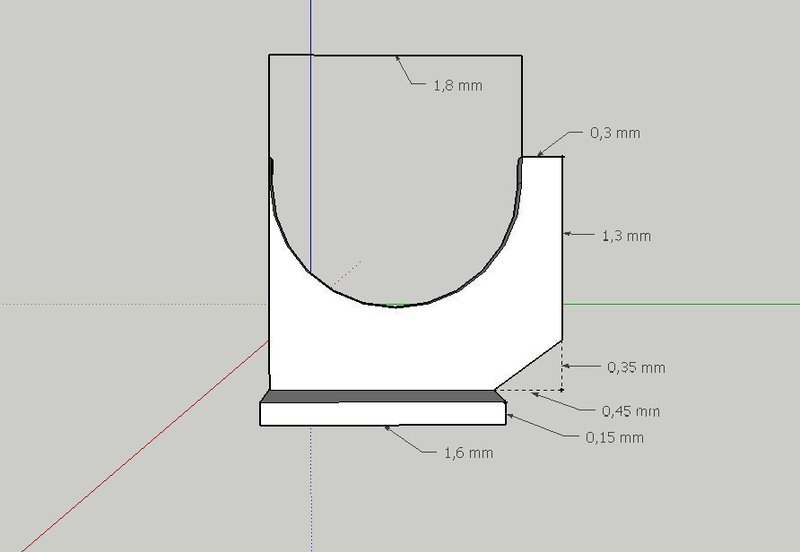
With these measures I can finally start with the production of the Supports. And what looks so enormous in the pictures is, in reality, so small that these differences in measures are unlikely to be noticed. ![]()
![]()
there is just so much detail going into this. Great stuff to see ![]()
Thanks John, ![]()
yeah, my attention to detail, curse or blessing, that’s here the question … ![]()
![]()
Hello everybody,
today I finally want to start with the production of the Supports, which immediately reminded me of the stressful fiddling with the Pipe Supports under the pipelines of the SSWS. ![]()
I was immediately confronted with the question of how to get these tiny things as reproducibly as possible, which I had managed that time too. ![]()
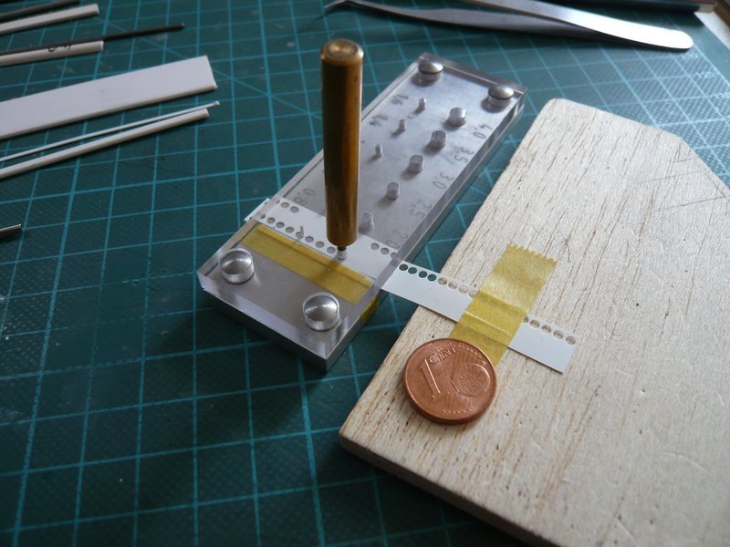
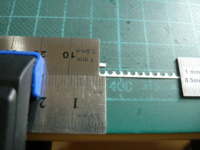
And this started again with the punching of the gutter roundings (Ø 1,8 mm) with the Punch & Die Set. In order to maintain the same height of 0,6 mm below the rounding, I have applied a strip of styrene foil (0,2 mm) 0,6 mm in front of the punch opening (Ø 1,8 mm), at which I have aligned the styrene strip (0,1 mm). ![]()
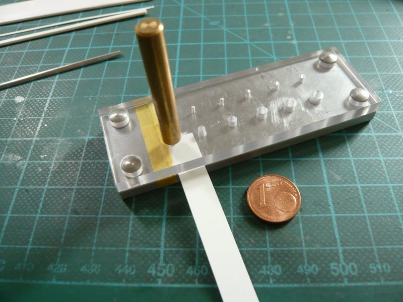
And then everything went quickly. ![]()
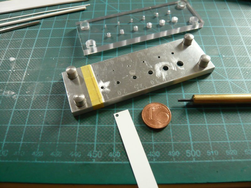
However, with too great zeal, I had left too little space in the first row (above), ![]() what I then have corrected in the second row, because also for the later separation of the supports one needs sufficient distance, in particular to manage the front narrow support edge well.
what I then have corrected in the second row, because also for the later separation of the supports one needs sufficient distance, in particular to manage the front narrow support edge well.
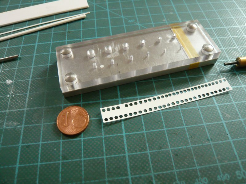
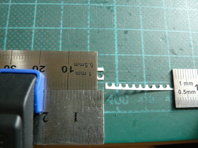
But the second row was then perfect. ![]()
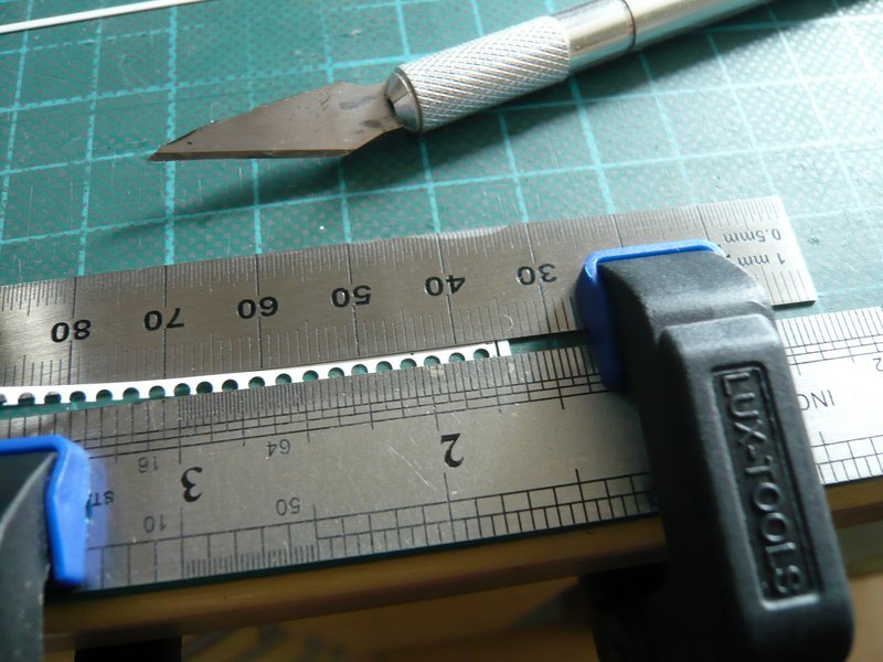
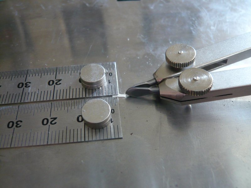
Then the punched strip had to be accurately separated in strict accordance with the support height of 1,7 mm. However, since this cannot be marked accurate enough, I have clamped the perforated strip between two steel rulers, fixed by means of two spacers, and could thus carefully cut the punched strip with the cutter. ![]()
The next tricky thing was the uniform separation of the supports with a width of 2 mm, so that an overhang of about 0,3 mm remains at the front edge. ![]() And here, too, my then-trick with the two steel rulers proved successful.
And here, too, my then-trick with the two steel rulers proved successful.
First of all I needed a few attempts to cut an end stop with exactly 2 mm length with the cutter-chisel. ![]() And by means of the edges of the steel ruler and the spacer I now had a good guide for alignment the cutter,
And by means of the edges of the steel ruler and the spacer I now had a good guide for alignment the cutter,
and could cut off the supports with quiet hand,
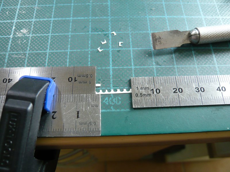
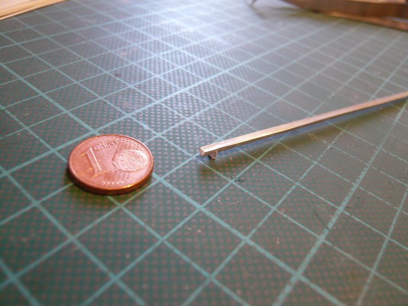
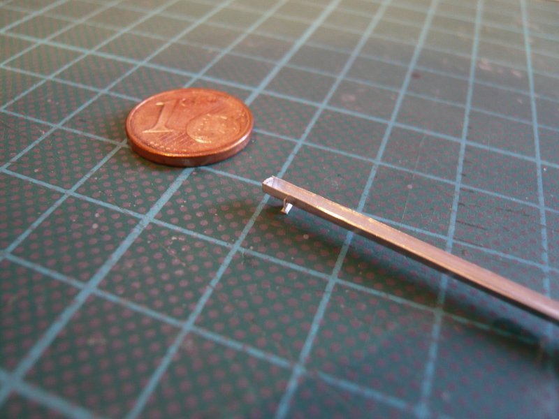
which actually gives nearly uniform supports. ![]()
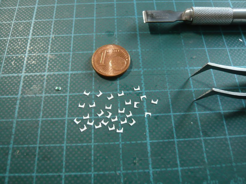
Now only the lower corners have to be cleverly separated, but if possible without sneezing. ![]()
And then these tiny supports have only to be glued to the lower 0,7 mm narrow web strip (0,15 mm), but it’s only questionable how this can be done best … ![]()
But maybe someone of you has a good idea in stock … ![]()
![]()
Hello everybody,
well, then I have to think for myself. ![]()
After a long period of testing, I have managed to position the support clamped in tweezer nearly in the middle of the 0,7 mm wide strip fixed between two rulers, and to brush it carefully on both sides with MEK. ![]()
And here is the result of my first test. ![]()
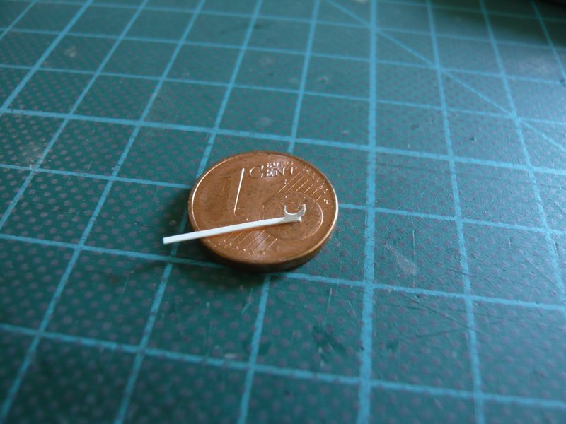
Afterwards, I’ve carefully cut off the ends of the strip, and the first prototype of such a support is finished. ![]()
And so it looks like with provisorally placed gutter on the support.
But when I imagine that I have to tinker about 32 pieces of this support type, which somehow have to be glued with CA on the gutters, then a rather queasy feeling is creeping over me already … ![]()
But let’s look, time will tell … ![]()
![]()
Sent you a PM regarding this assembly earlier today.
Have sent you a reply. ![]()
![]()
Responded .
That looks pretty good on the gutter. It was worth all the hard work.
Definitely John, that’s why I continued. ![]()
![]()
Hello everybody,
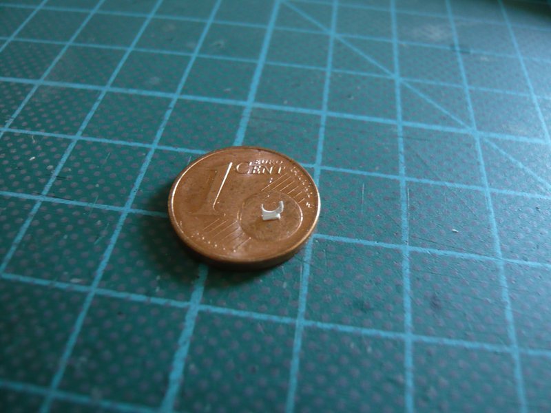
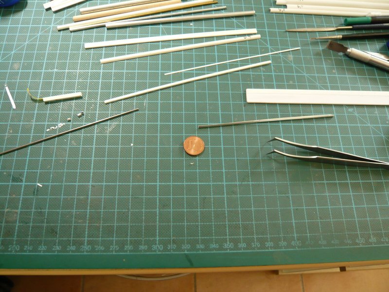
on my macros it always looks so huge. ![]() But that is not the case, how this photo here from my normal working position at the desk shows, whereby I hope that you do not ask now, where the support is …
But that is not the case, how this photo here from my normal working position at the desk shows, whereby I hope that you do not ask now, where the support is … ![]()
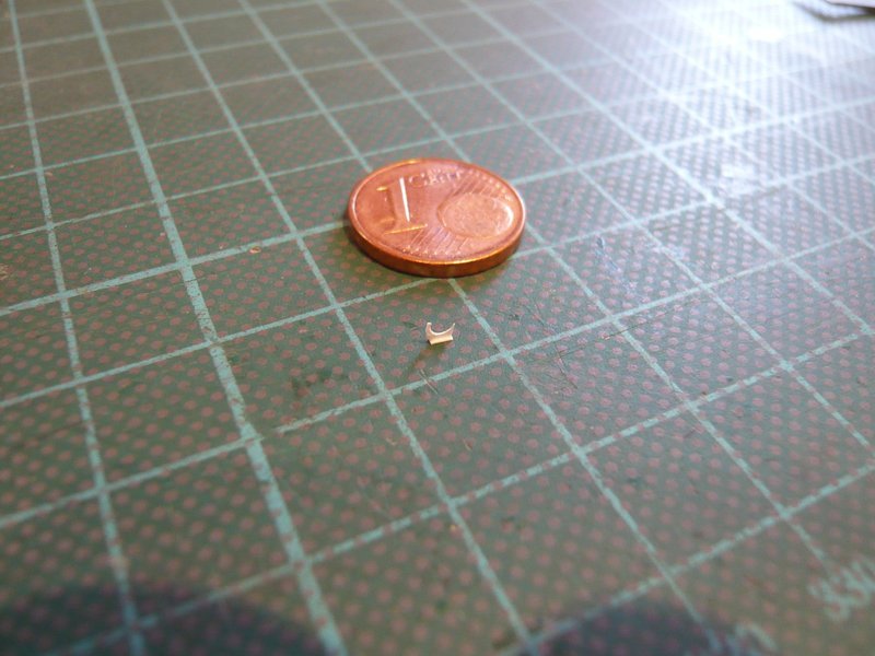
The problem with this matter is the extremely difficult handling of these tiny parts, as well as their fragility, since the bottom edge of the sickle is only 0,1 mm “wide”. ![]()
But by the gluuing with the lower flange the things at least stand upright, which might perhaps facilitate the later assembly on the gutter. ![]()
The stupid is only that there are hardly any suitable places to grab with the tweezer, because only the front approximately 1 mm long but very narrow part (0,3 mm) comes into question, since the lower edge (0, 6 mm x 1,6 mm) must be accessible for the MEK brush. ![]()
The tip of the scissors tweezer is almost too large and also squeezes this front narrow web too much, which is why you need a different solution.
I had first helped me with a clamp over a normal tweezer, whose bite was tolerable thereby. 
And this clamp handle must now be positioned only still centrically over the fixed narrow strip, and then the pointed MEK brush comes. ![]()
For glueing together the supports onto the gutter I imagine that I fix the gutter with the rounding upwards at an end stop, and then the supports are sinked in the clamp grip over the roundness and carefully painted with MEK, after which they hopefully stick. This sounds adventurous indeed, but could work.
Before the assembly of the gutter, the next tricky procedure of the airbrush painting would come, presumably first outside and then inside, for which I still have to think over a skillful holder for these fragile structures. ![]()
But somehow I’ll make it, I think, even if the gutters should get some bumps, but the real gutters had also their traces of usage back then …
But initially I still have to struggle with the rest of the supports … ![]()
![]()
A suggestion that works for me…although I rarely go down to your level of micro…
It works provided that you have a steady hand to hold the item in place long enough for the glue to “grab”. Which is why I use fast-drying glue like the Tamiya shown, or superglue.
Hi Tim,
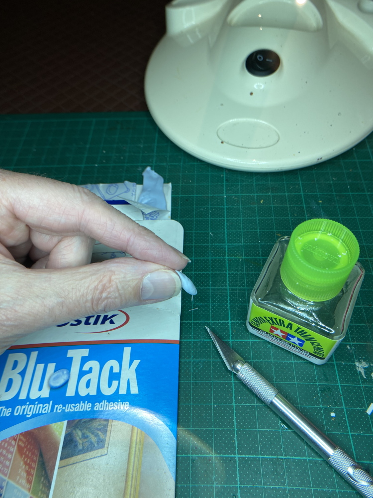
this TAMIYA Extra Thin Cement I also know. I use UHU Easy Fluid, a CA, which can be corrected for a short time. ![]()
![]()
Hello everybody,
in the meantime I have refined my previous clamping device and stabilized it. ![]()
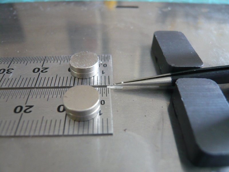
For this purpose, I fixed my most pointed tweezers with the support between magnets on a steel plate so that the lower edge of the support rests planar on the web strip, which is also fixed between two steel rulers.
The clamp is required because the tweezer is non-magnetic. ![]() In the clamped state, I could now take them away, because the magnets are strong enough, but it does not interfere, because the splice is freely accessible with the MEK brush. And besides, nothing should shift.
In the clamped state, I could now take them away, because the magnets are strong enough, but it does not interfere, because the splice is freely accessible with the MEK brush. And besides, nothing should shift. ![]()
This is by the way the finest marten brush (5/0), which I could find. ![]()
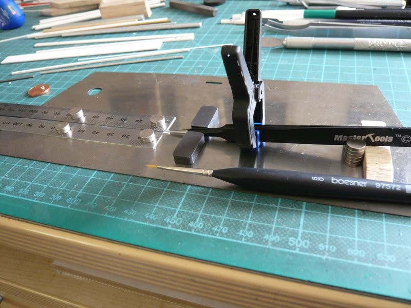
The advantage of this arrangement is that I can position the rulers with the inserted strip relatively easily and above all fairly precisely centrally under the support by careful shifting and can then lower it. ![]()
And with the necessary calm and patience I will manage it already. ![]()
![]()
Just make sure, this does not mean go fast. ![]()

![]()
No faster than 70 mph!!! ![]()
![]()
Hello everybody,
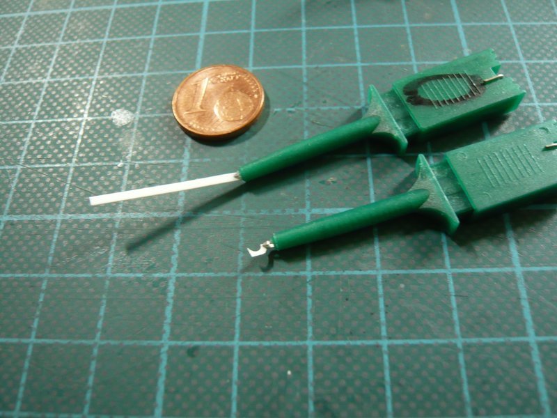
a friend from the German Raumcon Forum has sent me two special clamps, which of course had to be tried immediately. ![]()
Their function is relatively simple. As can be seen in the picture, when the two parts are pressed together, a small, opening clamp is pushed out of the tube, with which the part can be gripped.
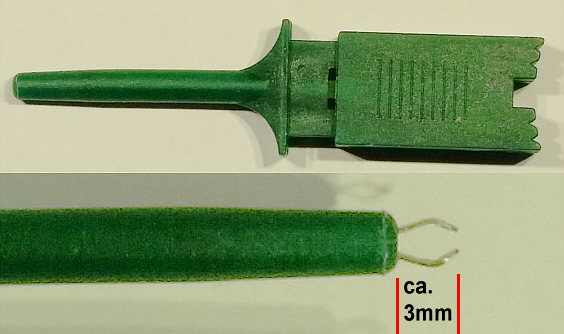
When releasing, the clamp snaps the part and is retracted by an internal return spring, but in this way also thin or narrow parts with diameters/widths ≤ 1 mm, which would not be good for my dainty supports. ![]()
While the upper 1,5 mm wide strip stops before the opening of the tube, the lower 0,8 mm wide strip would be pulled in by the spring force of this original clamp. ![]()
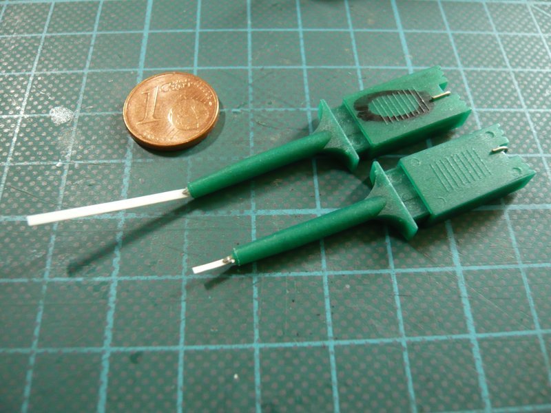
Therefore my friend has inserted a weaker spring in the lower clamp, whereby the pull-back force can be dosed, but now the stability of the clamp grip is now no longer sufficient to be able to position parts like my supports exactly before gluing. ![]()
Therefore these clamps are unfortunately not suitable for the handling of these tiny supports, but for other purposes they could be quite useful. It would be more convenient for the handling, if the inner clip could be rotated by 90°, what might be possible.
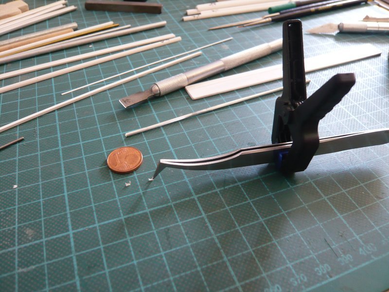
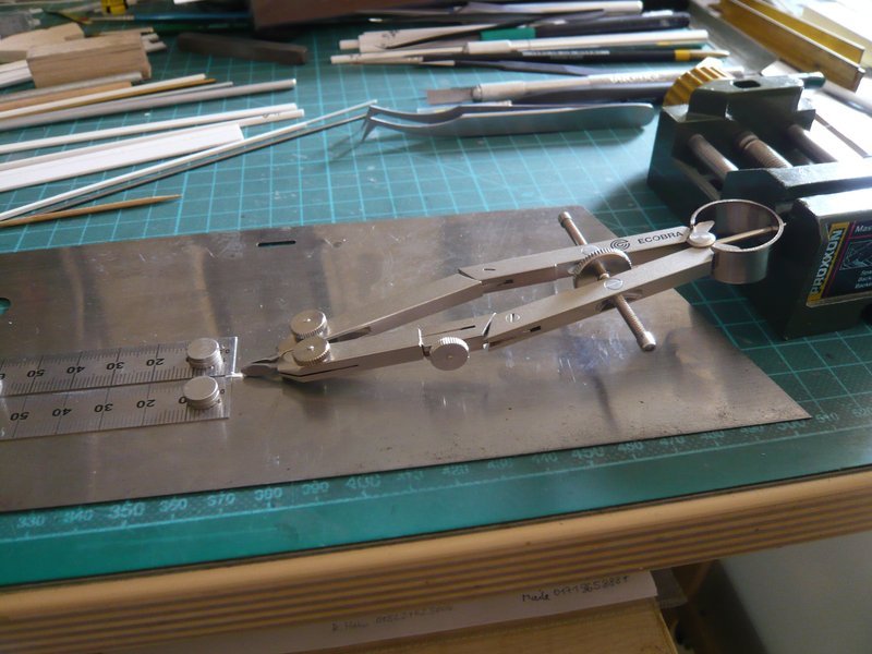
That’s why I’ve continued fiddling around with it, and I came up with the idea of converting my adjustable cutting compass to an adjustable “tweezer”, that’s why I replaced the tip by inserting a second cutting edge. ![]()
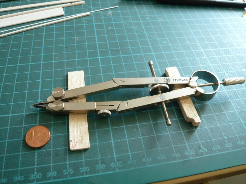
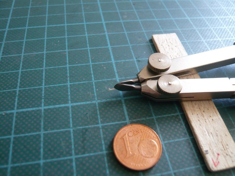
As a result, the support can be clamped on a suitable base between the two cutting edges so that the clearance under the support corresponds approximately to the thickness of the strip on which the support is to be glued. ![]()
Depending on the strength of the clamping grip of the cutting edges, the position of the support can also be adjusted relatively easily in this way.
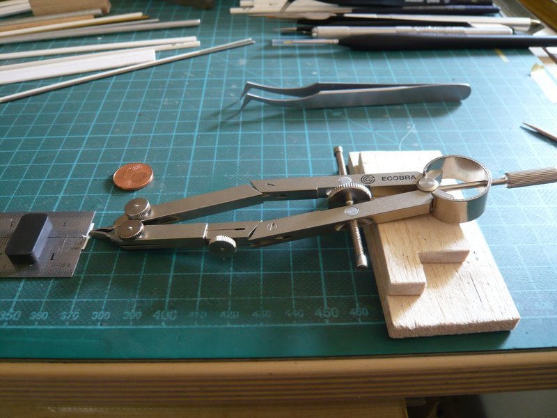
This clamping device can also be easily transferred to the sheet metal and fixed in the mini-vice.
And after centering the support over the strip, the strip can then be glued in flat contact with MEK.
This new method is much simpler and above all more stable than the previous somewhat wobbly arrangement with the tweezer fixed between the magnets and the top clamp. ![]()
![]()
Brilliant use of tools to get those micro parts assembled.