Hello everybody,
after the wearisome Gutter chapter has been finished except for the paintwork, I want to take a relaxing look ahead and bring the highlight of the lighting of the MLP back into the game, which will soon be back on my agenda. 
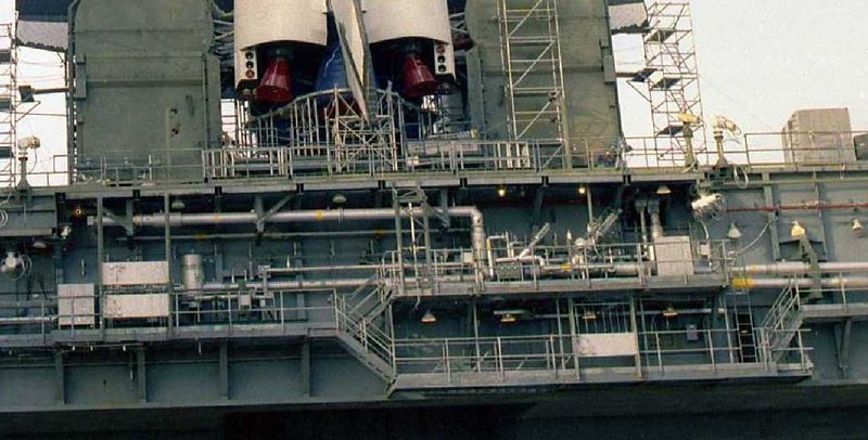
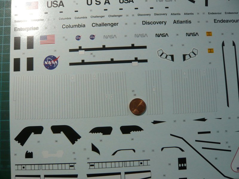
During my first inventory (2014) I had found these 21 lamps on the Side 1,
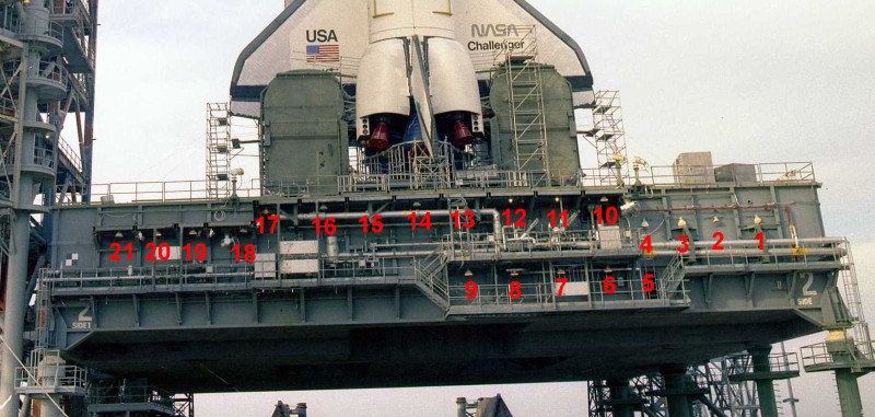
Source: retrospaceimages.com (STS-6)
which I had to correct in hindsight, since the Lamp 5 during STS-6 (1983) did still not exist, like one can see in this image of [STS-28 (1989)/color, but rather much later, whereby the number of lamps is reducing to 20. ![]()
Since the wiring design of the Super Power bank was construed on max. 8 LEDs per circuit, my original lighting plan included these 3 circuits with a total of 20 lamps. ![]()
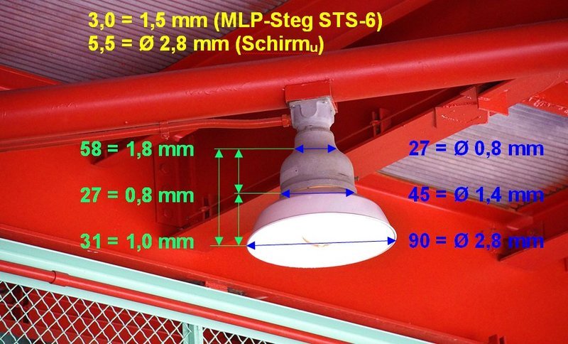
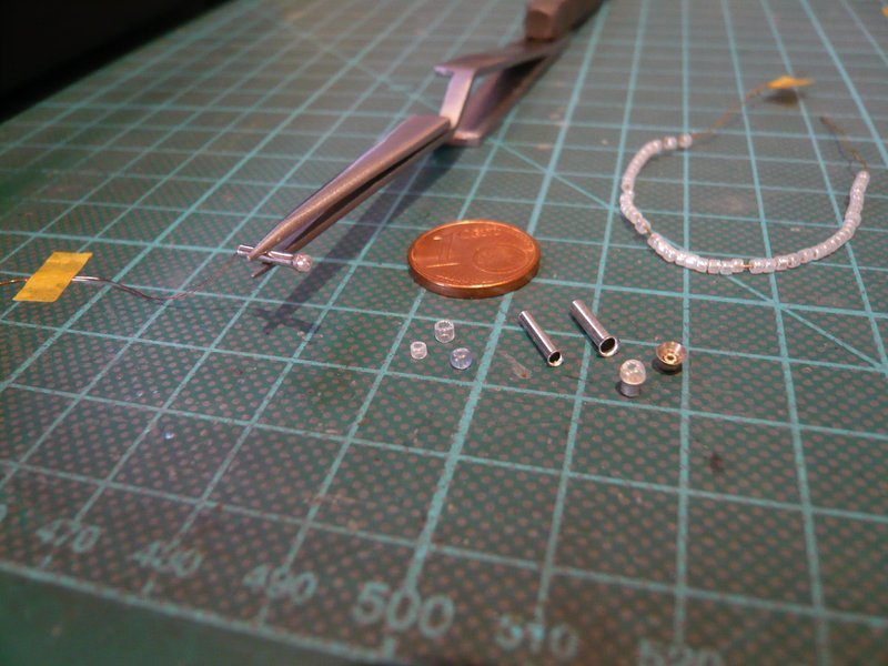
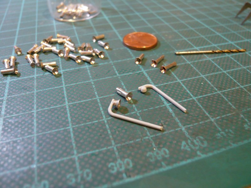
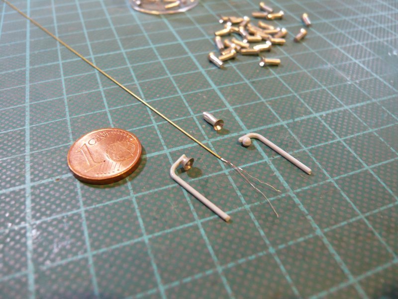
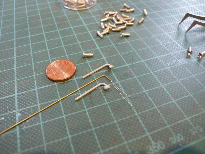
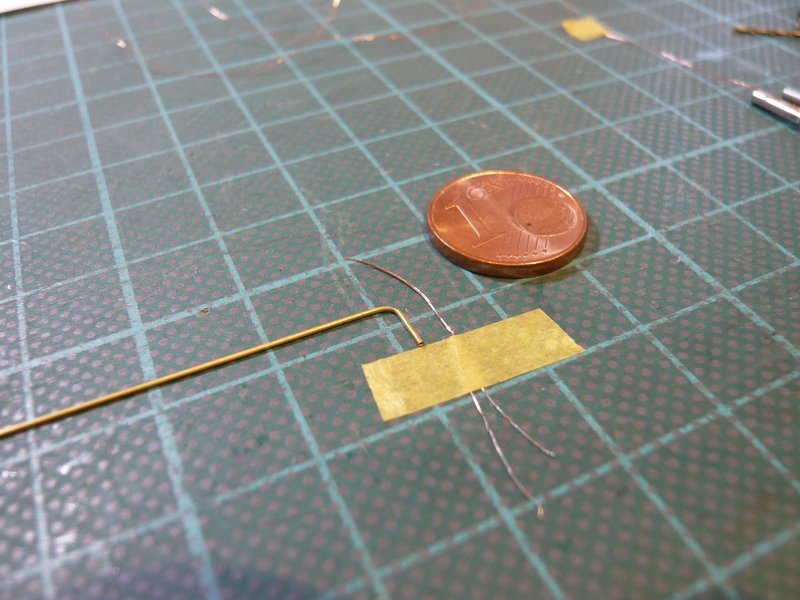
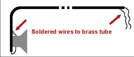
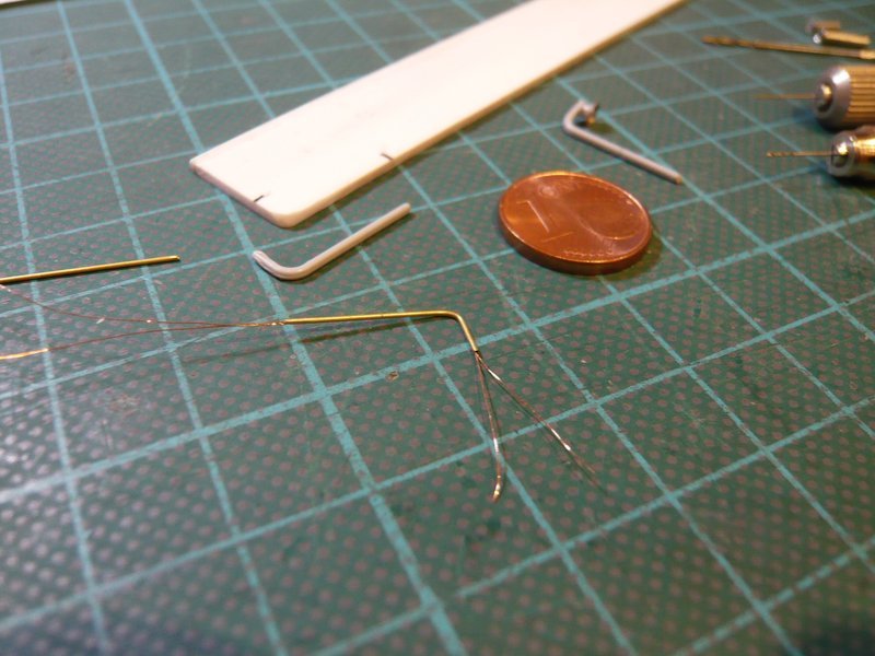
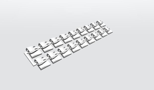
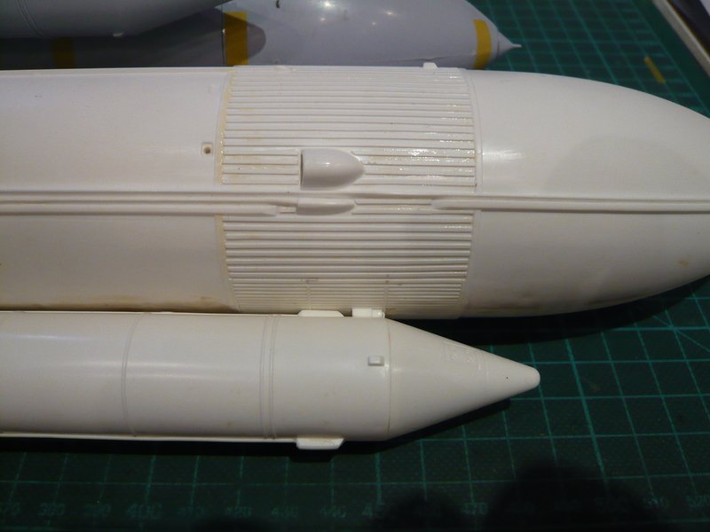
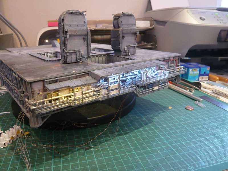
During the preparation of the later installation of the circuits on the model, it is important from a practical point of view to think about how the thin supply lines and the return conductors of the individual circuits should be laid preferably. Withal it is necessary to consider how to pass with supply lines and lamps through the narrow spaces under the canopies between the pipelines and struts and past the tiny fittings and also to glue them, what should not be so easy. ![]()
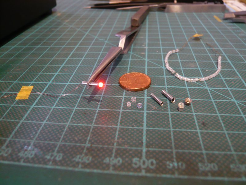
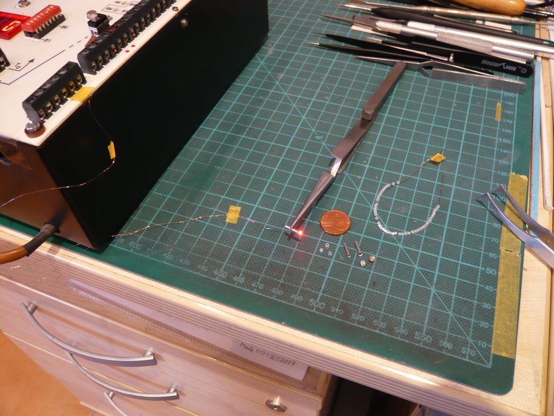
In my first lighting trials, the matter was easier, because I had then only provisionally laid the individual LED cables under the canopies, which now inevitably needs to be done differently in the final solution. ![]()
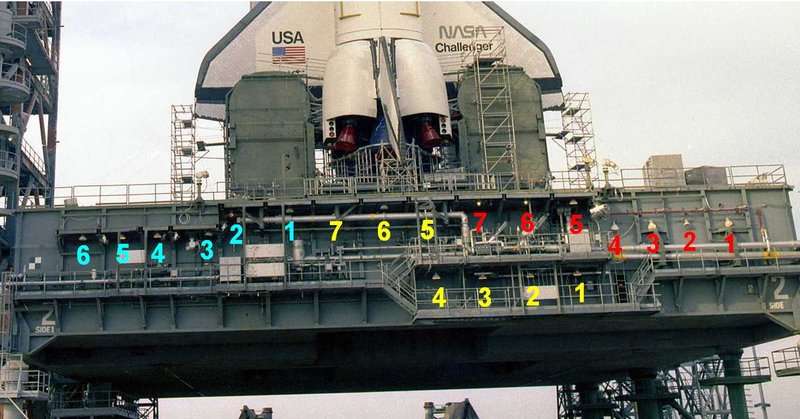
That’s why I have changed the division of the circuits, which now looks like this. Thus there will be 1 circuit (red) with 8 LEDs connected in series, and 2 circuits (yellow/cyan) with 6 LEDs each. ![]()
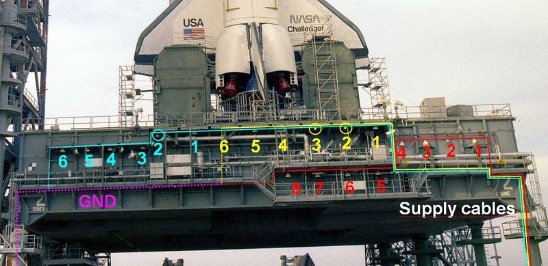
Source: retrospaceimages.com (STS-6)
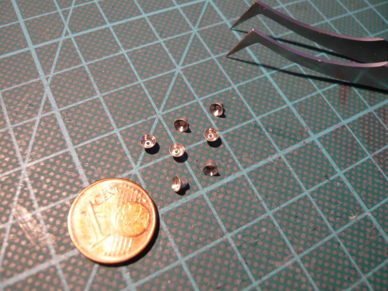
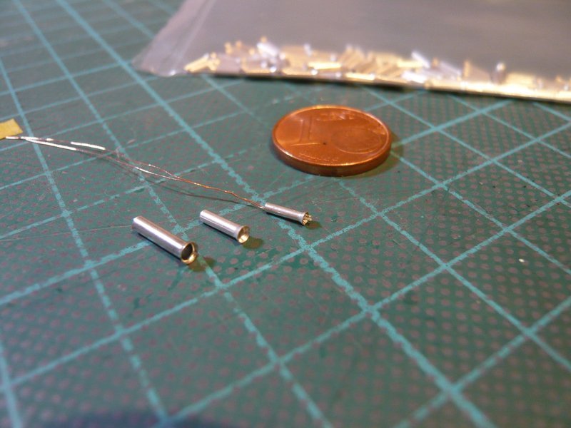
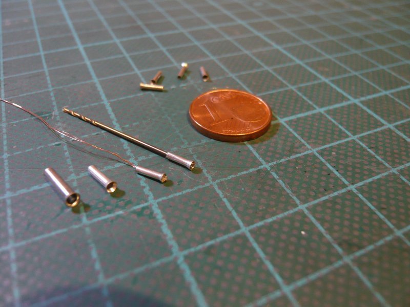
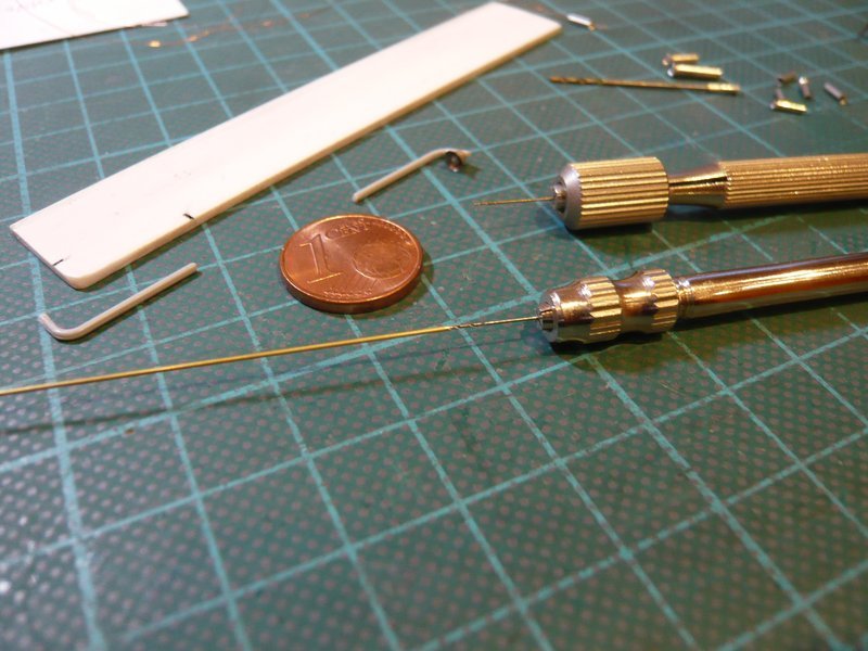
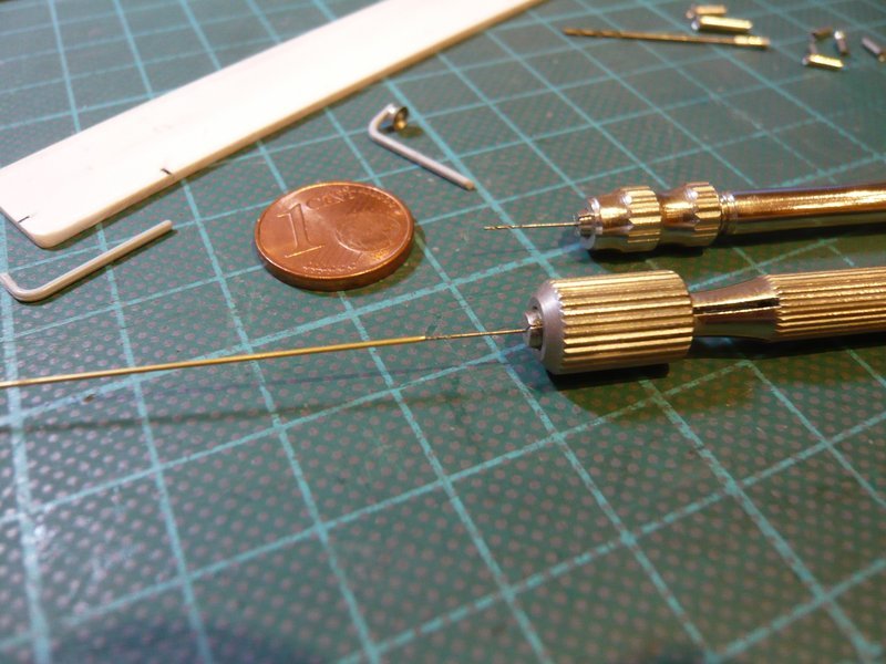
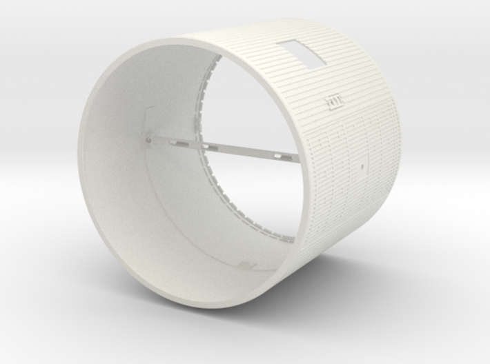
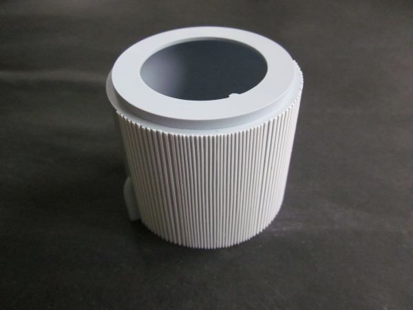
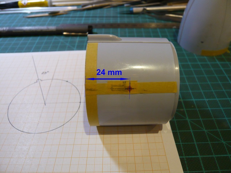
Therefore I imagine the installation so that the three supply cables are led through the front right Pedestal, preferably detachable via mini-connectors, ![]() in order to be able later to let drive the Crawler with the MLP a short way on the Pad diorama.
in order to be able later to let drive the Crawler with the MLP a short way on the Pad diorama. ![]()
In contrast to my original plan, it will be more favorable to lead the first circuit (red) along the wall to the right Access Platform and then under the LH2 Access Platform. As with the other 2 circuits, the return cables then run via a Ground (GND) bus (pink) below the left Access Platform and the front left Pedestal.
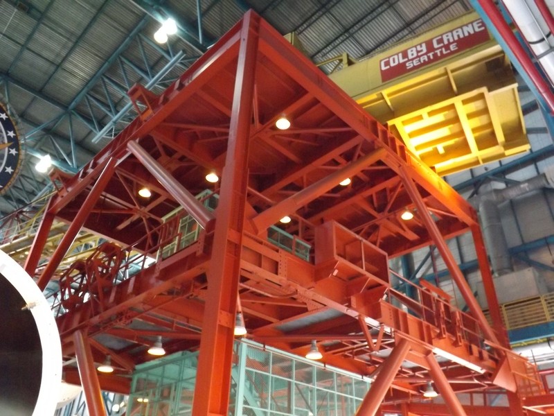
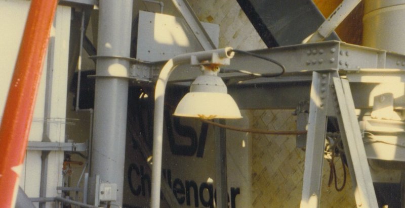
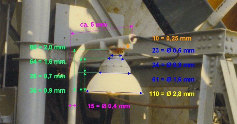
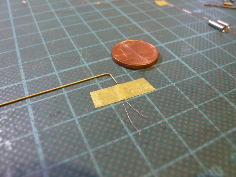
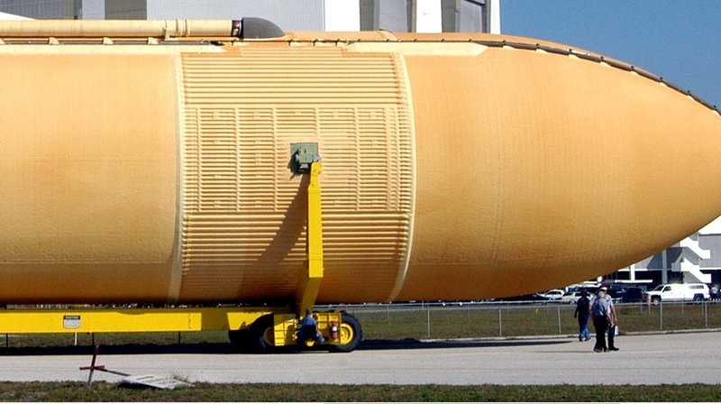
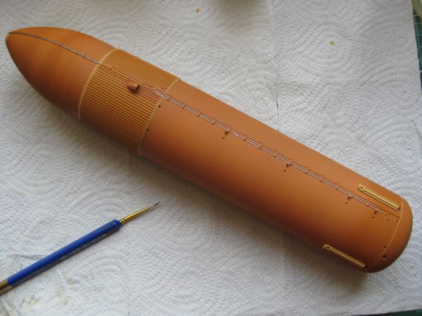
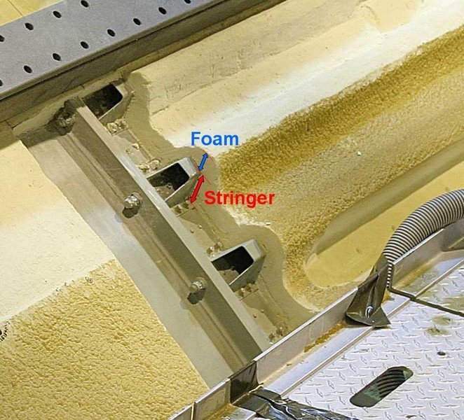
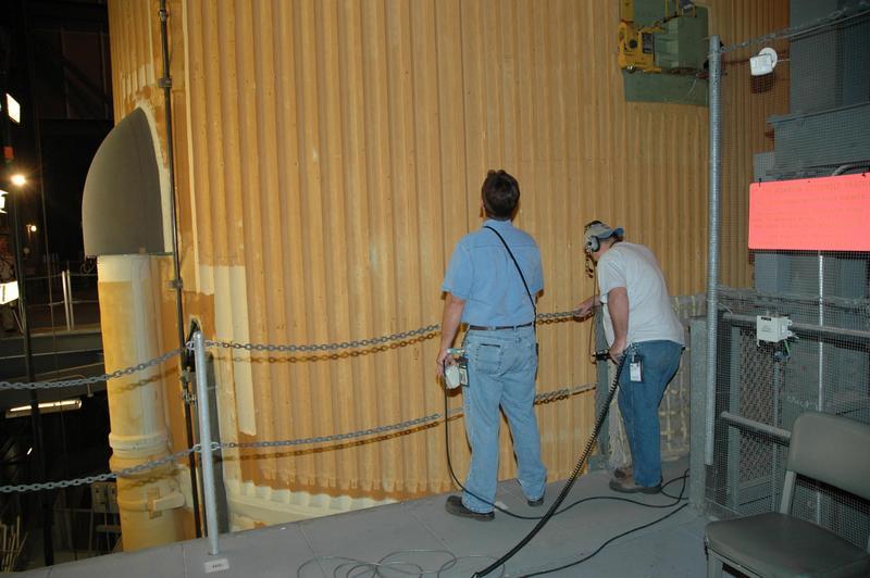
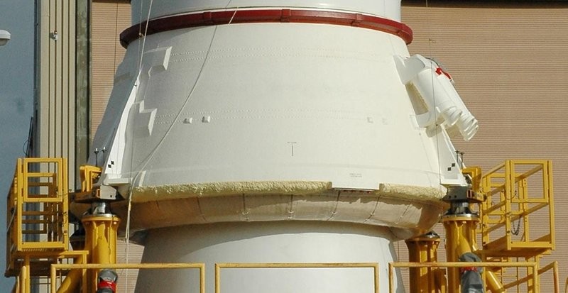
The installation of the second circuit (yellow) will presumably be the most difficult act because the place under the Blast Shield over the valves of the LH2 Valve Skid is very tight, as one can easily see here. ![]()
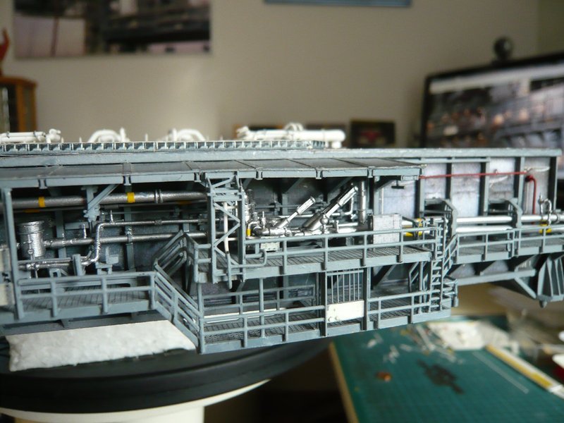
But we’ll work it out somehow … ![]()
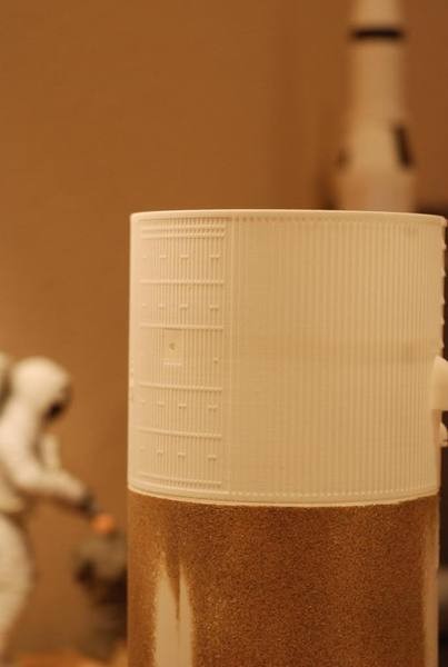
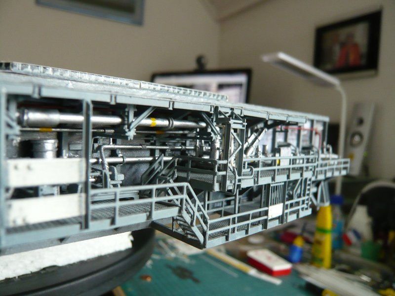
The installation of the third circuit (cyan) hopefully will be a bit easier, because there is more space above the LOX Valve Skid and under the left Blast shield.
As far as with this little trip to the illumination of the clouded minds. ![]()
I’m sure that this Lighting subproject will be a lot more enjoyable and inspiring than the tricky Gutters were! ![]()
![]()