This is epic construction with the most amazing detail… each new update has its own wow factor… And seeing the shuttle on the platform and the size of it all even at this stage … Staggering!!
1 Like
Thanks John for your nice compliments. ![]()
I’m always amazed for myself what crazy stuff I’ve already scratched so far … ![]()

1 Like
Hi friends,
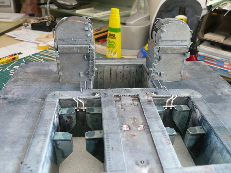
now I want to continue with the SSWS pipes at the front end of the SRB holes that I had ever been shown. ![]()

Source: capcomespace.net
In this picture you can see the arrangement of the two pipes between the SRB supports even better.

Source: capcomespace.net
And so do the associated templates from the Paper Kit look like, here is the lining of the back wall, although belonging to the other hole, but very similar to the real thing.

And here’s the cover of the SRB-Blast Shields with appendages from which one should now conjure these pipes with 1 mm diameter. 

But since I do not even want to try out, ![]() I’ll scratch these details again in plastic and start with the left hole’s pipes.
I’ll scratch these details again in plastic and start with the left hole’s pipes.
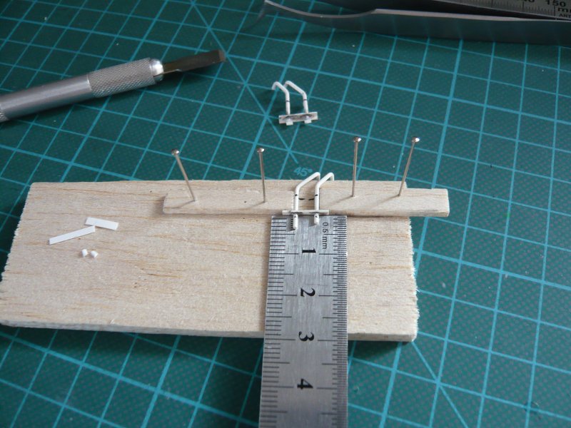
For the pipes I’ve used Evergreen Rods (Ø 1 mm) and for the lower bracket L profile (2,5 x 1,5 mm).

The pipes are not glued, as they still need to be cut down after fitting.

Then I have already drilled the holes in both Blast Shields to fit the pipes.

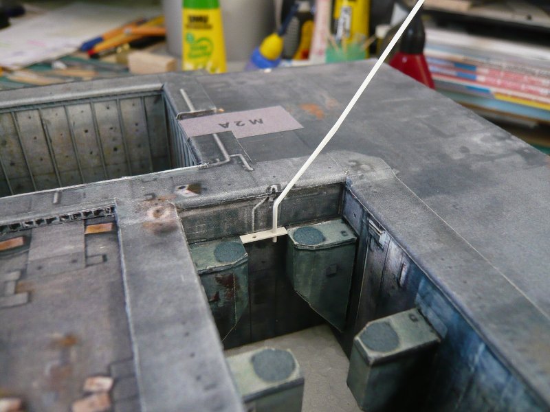
And as one can see, the first pair of pipes fits after some corrections quite well. 
Where the profile is inserted, yet little support underneath come later.


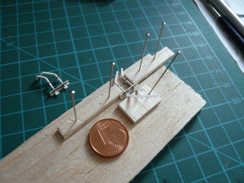
Now the pipes at the lower ends but even have those baffles, and they were a bit trickier. ![]() These are Styrene strips (0,2 mm), which I glued again with MEK and then cut.
These are Styrene strips (0,2 mm), which I glued again with MEK and then cut.


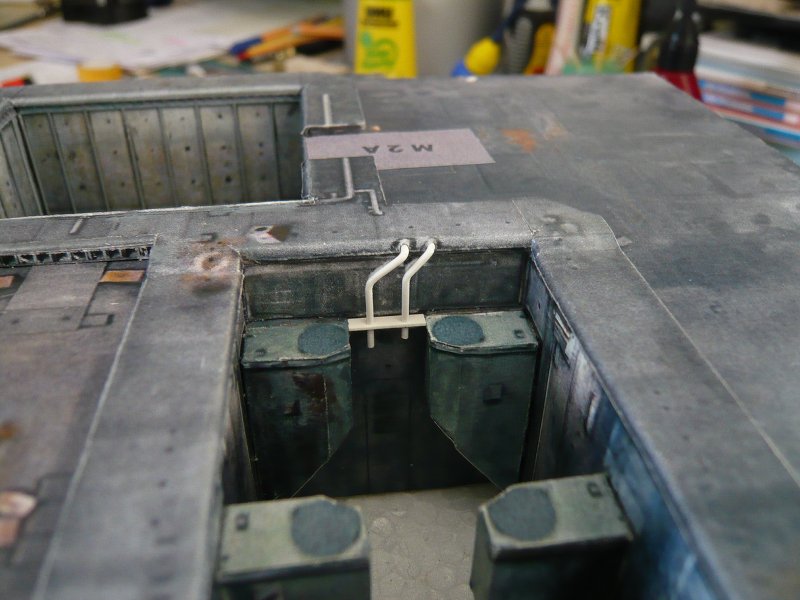
And so it looks like so far.

A few things are still missing, but next time it will be continued with the second pair. ![]()
1 Like
Hi there,
before I started with the second pipe pair, I still have experimented a bit with the mountings of the pipes. Unfortunately, the photos of these pipes are not sharp enough to see the details more closely. But I mean, there are holding clamps with which the pipes are connected to the brackets on the rear wall. The middle clamp is clearly a clamping ring for detachable connection of pipes, as can be seen in many places of the thicker SSWS pipes. Perhaps this middle clamping ring is only a sleeve. 
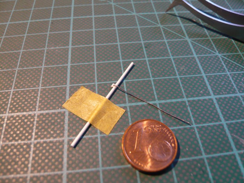
And this I have tried to indicate by a tape roll and a sleeve made of aluminum foil, whereon the clamping ring is sitting, made of lead wire (Ø 0,2 mm). But the handling is already at a single round profile a pretty tricky matter,
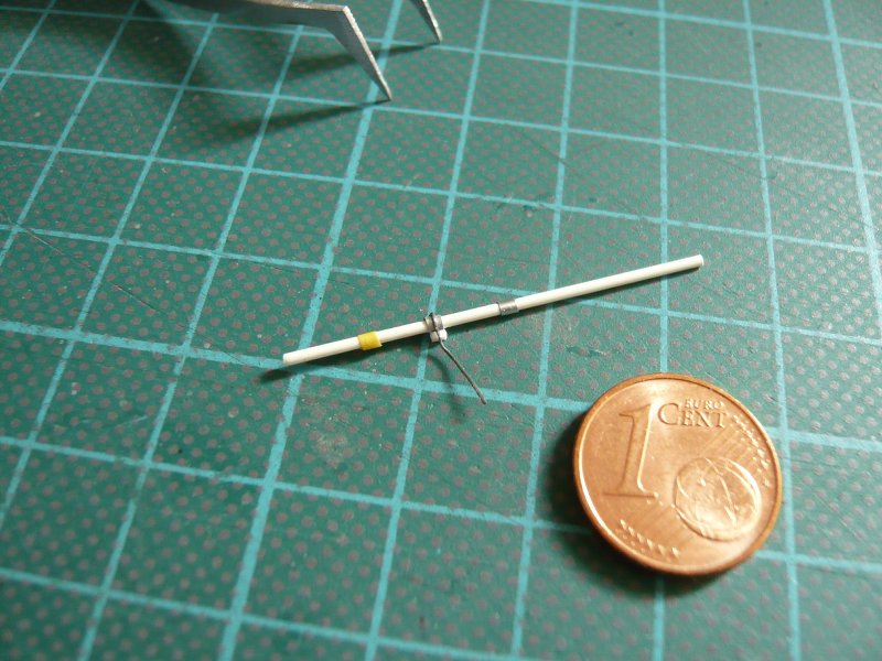
let alone the finished pipes pair.
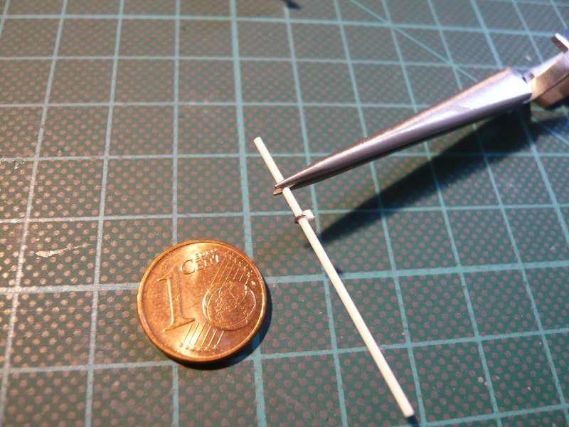
Therefore, I have decided to omit the sleeve and to indicate only the clamping ring. 
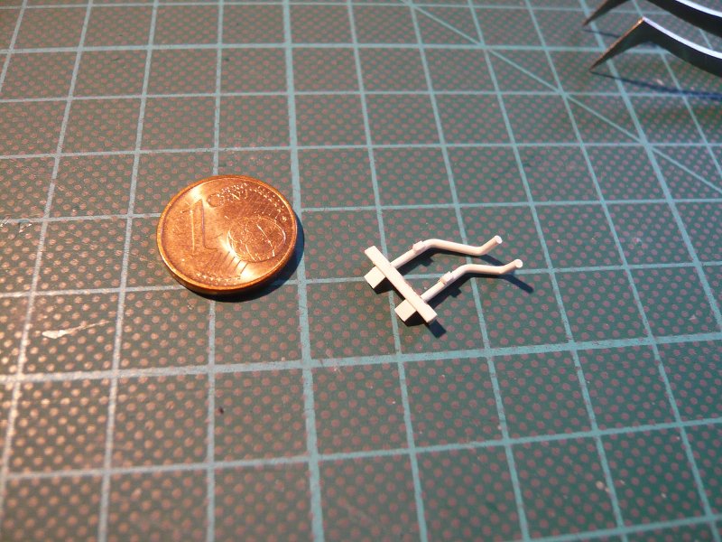
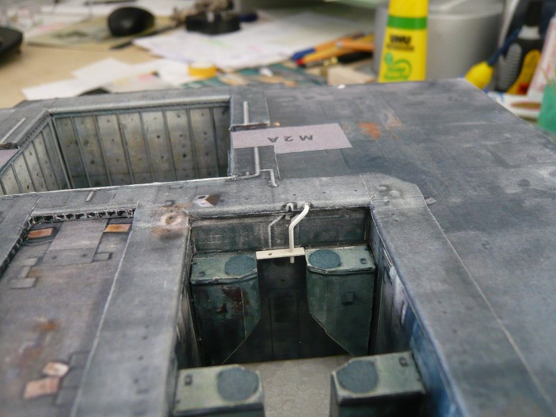
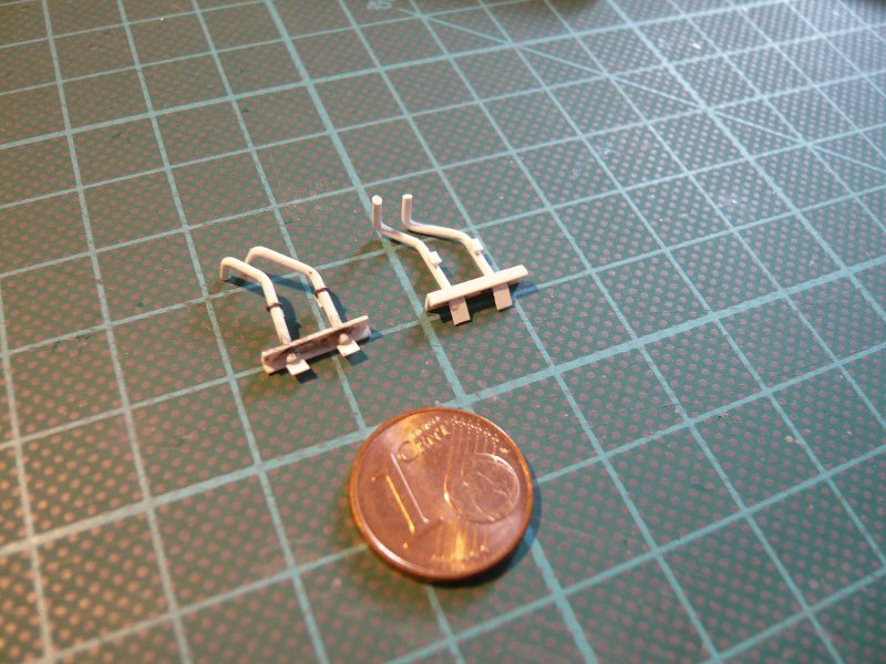
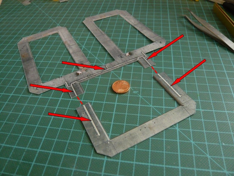
For the small brackets I finally used tiny T-Beams made of Evergreen strips,
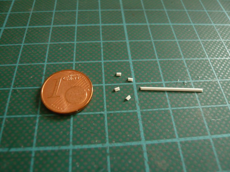
which then end up looks like this.

So far so good, and therefore, now to the construction and assembly of the pipes in the other hole in an analogous manner.
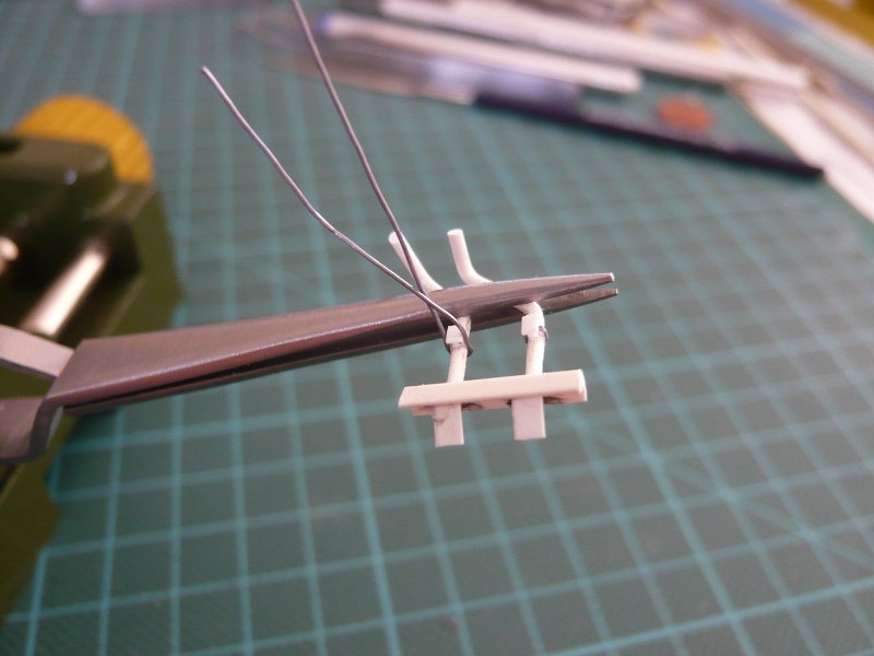
And so back to the trickier detail steps in the installation of mini-brackets, baffles and clamping rings in the following images.
The conclusion was again the stressful attachment of the lead wire, since gluing must be done with CA. ![]() If namely the first gluing is holding not immediately, there are problems, because then you have to remove the CA again only what is in these mini-contacts really crude. And then the excess wires must be removed with the cutter. It can happen, that the wire ring redissolves or breaks off the bracket.
If namely the first gluing is holding not immediately, there are problems, because then you have to remove the CA again only what is in these mini-contacts really crude. And then the excess wires must be removed with the cutter. It can happen, that the wire ring redissolves or breaks off the bracket. 

But then the second pipes pair was finally made,

and the pipes look like after the final fitting in the SRB holes,
which can be painted now. ![]()
1 Like
Hi folks,
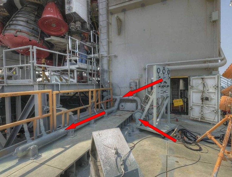
so that the paint is also worthwhile, I will scratch build another SSWS pipe. It is this line here, which runs around the SSME hole, as you can see here on the templates of the Blast Shield covers from the Paper Kit.
Thereafter, this ring line should obviously run through the TSM’s, which is not true, as one can see in the following image. Instead the supply lines come in front of both TSM’s out of the MLP deck and then branch into a strand with several nozzles along the hole.
3D-rotatable view of this area at nasatech
Source: nasatech.net
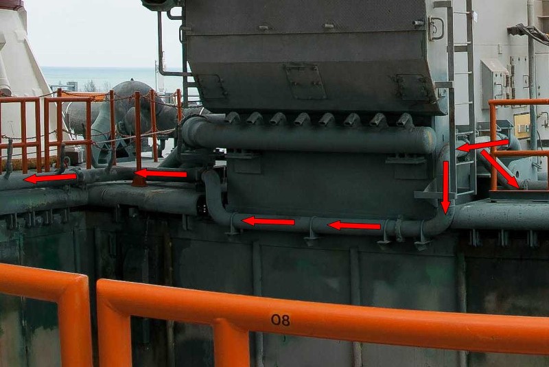
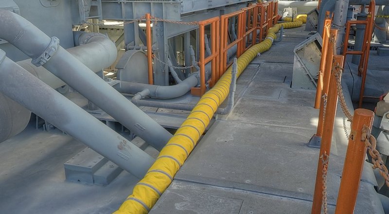
In this image one can see the rest of the line that runs along the top of the hole on the inside of the TSM’s along and then again to the top and around the hole.
Source: NASA
As one can see in the images and panoramic shots, this rear part of the line over the entire length has also a series of spray nozzles.
3D-rotatable view of this area at nasatech
Source: nasatech.net
So much for the presentation of this line, now I need only to determine the dimensions of the associated supports and nozzles, and then I can start with the scratch building. The diameters of the pipe and spray nozzles correspond with 1,4 mm and 0,5 mm with the already finished pipe on the rear wall. ![]()
2 Likes
Wow, I think you must have been either a surgeon or a plumber in a past life - when will you start the pressure-tests? ![]()
![]() Excellent & meticulous work Manfred
Excellent & meticulous work Manfred ![]()
Thanks Tim for your funny answer, I always say, in my next life I will be a gardener … ![]()
BTW, the SSWS isn’t finished yet, so the test will have to wait. The tricky pipe connections are yet to come. Stay tuned, you will be amazed. ![]()
1 Like
Hi Guys,
before continuing with these pipes, I have to correct something my last post. 
The presented piping system is not a part of the Sound Suppression Water Sytems (SSWS), as I had previously thought. As I have discovered these pipes belong to the Fire Suppression System (Firex) which is activated as a result of problems with the SSME main engines and means a launch cut off (Redundant Set Launch Sequencer - RSLS - abortion) at the last moment immediately before the SRBs are ignited.
I came across it in the evaluation of the reference material for the determination of the dimensions of the pipes and water nozzles, so among other things, when viewing photos and videos of SSWS tests. One can always only see the larger SSWS systems in the three exhaust holes and the Rain birds in action, but never these pipes of the SSME hole, but would not surprise, considering the haze of the massive volume of water.
But then I reminded me of images, especially where the fountains of water sprays were seen on both sides of the front hole in action, but just did not know where I should be looking.
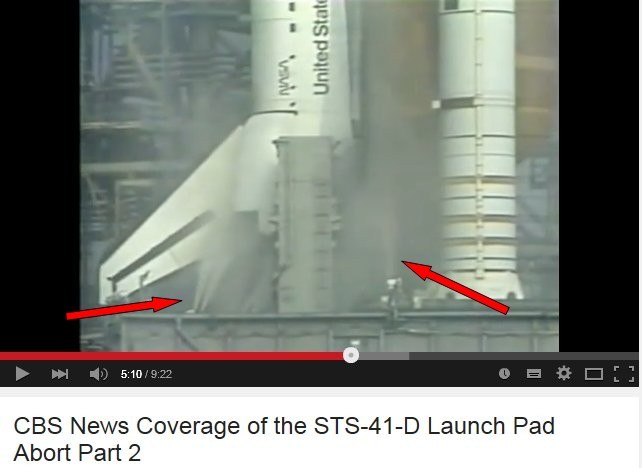
After a longer investigation of photos and videos from launch aborts I’ve then been able to find and hit the STS-41D mission, in which such a RSLS abort took place for the first time. Similar aborts there were also in the missions STS-51-F, STS-51, STS-55 and STS-68.
In this STS-41D-Video (from 4:48) one can see these water fountains in front of and behind the LOX-TSM after activation of the system.

And after this very interesting technique escapade again to practice and first again to the laborious determination of the required dimensions.
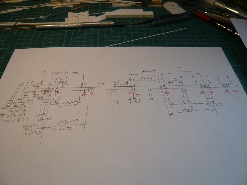
Here is my first time rough sketch with all sorts of sizes/calculations and positions of the pipes with spray nozzles from the Blast Shield on the back wall to the front of the SSME hole,
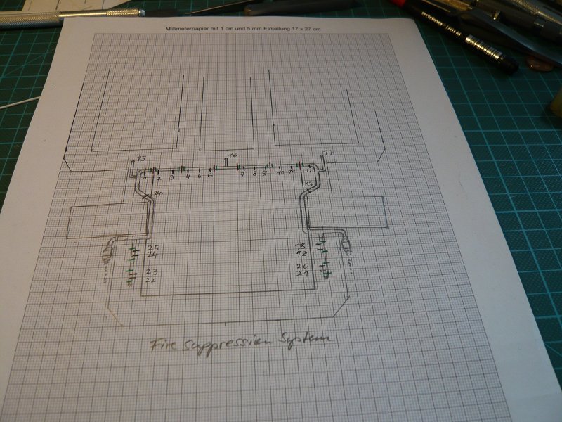
and here is my scale drawing with the supports (green), clamping rings (red) and the 25 spray nozzles (black), but this is hardly visible at this resolution.
And here are the materials that I want to use,
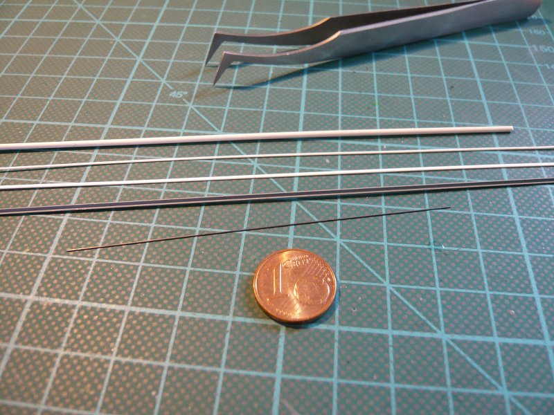
round profiles Ø 1,4 mm and 0,5 mm for the pipes and nozzles on the Blast Shield, an Evergreen strip 0,75 x 0,38 mm for the supports and 0,2 mm lead wire for the clamping rings and brass angle profile 1 x 1 mm for the supports below the TSMs.
That’s it for today, and next I will throw myself then boldly into this pleasure. ![]()
2 Likes
Hello everybody,
and now ready to begin the pipe bending for [color=blue]Fire Suppression System[/color], in which I want to go step by step. Although I’m not sure if I will be able to turn the whole line at once, but I will at least try.
If not, I would have to split the line, usefully then in each case on one of these supports below the TSM’s, or on the clamping band right, and cover the connecting point with it.

Source: NASA
The strands already shown with the two nozzle pairs forward before the TSM’s on the Blast Shield must be installed separately anyway.
3D-rotatable view of this area at nasatech

Source: nasatech.net
It was especially important to always compare the bends with the installation diagram,

as well as to try on the line on the MLP.  And as you can see, that already fits to the LOX TSM around quite well so far, although such tests are a delicate matter and I put the precious part rather quickly aside.

And that would be one half of the line made before, and it goes around the corner to the LH2 TSM.

So that to make these bends more closely, I again used my Balsa retainers, which give it more stability,

and the TSM replaced by a Balsa dummy, which is tough. ![]()

To adjust the height of the missing supports (0,75 x 0,38 mm) I put underneath a corresponding Evergreen strip of appropriate thickness.

To bend the tight curves above the Blast Shield this old TSM silhouette is a good orientation. ![]()


And now the acid test with the two TSM’s, which also is okay so far, both from the front,

and from the rear.

Now, of course, still missing a number of details such as the supports, clamping rings and nozzles at the rear part of the line, as well as the front two strands.
And then the ends of the line must be structured in front of the TSM’s that I have provisionally made longer. And at the beginning of the line from the upper deck there are this thickening with the flange (scroll there in the 2nd image) that I at least wanted to indicate. ![]()

Source: NASA
Let’s see what I will do next. ![]()
2 Likes
Hi friends,
and already there was the next surprise. By bending and adjusting the pipe for the Fire Suppression System above the Blast Shield of the TSM I have already noticed that the place was pretty tight there, what bothered me a little. And comparing this pipe with the running line above the TSM door then I noticed the different diameters, which should be the same.
And the final measurement actually found that I had once used for thicker TSM pipe Ø 1,2 mm rods, but on the other hand for the fire protection pipe Ø 1,4 mm. ![]()
This had also the consequence that the tight curves on the Blast Shield were a little too large, so that the two pipe ends directly in front next to the Blast Shield lay on the MLP deck. But there should still be a sufficient distance for the local thickening with the flange.
Purely by chance I still have found this great NASA Street view shot where you can see the details on location clearer than on the last image.

Source: NASA
To cut a long story short, I have provided new Evergreen profiles Ø 1,2 mm and have bent the pipe once more. But now I unfortunately realized that these rods are a bit more unruly in bending than those with Ø 1,4 mm. Firstly, the curves have repeatedly slightly bent up, and on the other they are with stronger bend even broken now and then, which had resulted some waste. ![]()
So I’ve been trying to preheat the pipe with a hair dryer, but this also was not successful because the opening was too large. So I bought this handy heat gun (Proxxon) with restrictor (Ø 9 mm).

And this device is almost perfect for preheating of the profiles, because you can heat exactly on the spot. ![]()
However, one needs a bit of tact, because the point to the softening of the plastic is reached relatively quickly, in which the rod suddenly becomes completely unstable. ![]() And since then the curves can not be bent smoothly and accurately enough, I had to refine my technique with the Balsa brackets for fixing the line sections.
And since then the curves can not be bent smoothly and accurately enough, I had to refine my technique with the Balsa brackets for fixing the line sections.
It is important to fasten firmly as possible to each section in front of the bend, so be clamped between the Balsa cards.

Then the bending point is preheated gently with the Proxxon, and at the softening point the line can then be easily bent with a balsa strips in the desired direction and fixed until cooling by means of pins.

Then each bend is “frozen” and retains its shape, as can be seen in the next picture.

And the fitting on the Blast Shield confirmed the perfect line run up to the TSM’s.

But now comes the tricky horizontal section below the TSMs that runs directly on top of the hole, and thus only about 2 mm lower than the previous line. So the line having to be clamped accordingly again.

But even this minimal bend can be done in this way.


And then the line can be unclamped again,

to carry out the next fitting. ![]()

This procedure is somewhat cumbersome, but ultimately leads to success, and that’s the main thing. ![]()
Next follows the same bend just a little further up, and then the remaining bends over the Blast Shield.
That’s it for today. ![]()
3 Likes
Hello everybody,
today I will go on with the bends at the Firex line, so first directly in front of the TSM upwards, and then over the Blast Shield to the right. And if I have measured correctly, the line between TSM and the front ladder should extend what has worked, fortunately.

For the bow behind the Blast Shield down I used again another Balsa jig.

Thereafter the line was re-clamped and then the bending followed obliquely forward. 

And up to this point it looks actually quite passable, in my opinion.

On this short end now I only need to install this thickening with the flange, which could be seen in advance.
Source: NASA
And so now for the scratch building of this part, for which I’ve bored up a round rod (Ø 2,3 mm).

In order to stay as much as possible when drilling in the center, first I have bored a smaller centering bore (Ø 0,8 mm) and subsequently bored up at Ø 1,3 mm, so that the 1,2 mm pipe fits well there through.


For the flange I have used an Evergreen strip (0,5 x 0,5 mm) and bent corresponding rings. For that I have wrapped the profile onto a core and subsequently heated with the Proxxon heat blower as long,

until it has retained the shape,

and then separated a few rings from the spiral.


For the clamping ring I bent rings from 0,3 mm lead wire,

and then glued both rings on the sleeve.


That’s it for now with this small stuff, true to the saying A penny saved is a penny earned. ![]()
3 Likes
Hallo friends,
here is the next update with the front end of the Firex line in front of the LOX TSM that takes bizarre forms slowly, and therefore be treated with caution.

At first I tried on the part with the flange.

Although the place in the corner next to the Blast Shield is close, the flange part fits there quite well.

Now, however, still missing the branching of the line forward, I’ve tried on. And then another thing of this place is a part, which has the same shape as the parts on the front and back of the TSM. These are presumably transport aids, which I had built during the re-construction of the TSMs. And see there, even this thing fits just about in between too.


Finally, I have still bent the line in front of the flange part and then cut where it empties into the upper deck.


And now to the tricky narrow and short bends above the Blast Shield, only this time on the other side, so everything is reversed. ![]()
And so the secure clamping of the line between the balsa boards slowly becomes already a delicate matter, because the need to sit tight as possible and must not move when bending under the hot-air shower. ![]()

In addition, you must now somehow protect the neighboring areas of the line too, because otherwise the rest could be deformed when it gets too hot in the vicinity, and then all the effort would have been for nothing. ![]()
But that’s not happening here at this point, fortunately, previously however, but already times now and then.

And how the test fitting shows, the line fits so far also quite good, as well as without the TSMs,

and with TSM’s, which of course is crucial.

Finally the second flange part was strung, cut the rest of the line and placed the branch line tentative.


So, with that my today’s destination is reached.
As next steps now the 18 tiny pipe supports and 25 spray nozzles are waiting for me, in front of what I already have little jitters. ![]()
But nevertheless I think it should be feasible, although it already is in the area of very small dimensions, what concerns the Water Nozzles. They are 0,5 mm in diameter, i.e. I also have to pre-drill the thin pipe (Ø 1,2 mm) with about this diameter in order to put the nozzles. And because thereby the cross section is fairly weakened, the line could already become quite unstable.
That’s why I tried this on a sample piece.

And as one can see, the test was successful, one just has to be careful not to pierce the line. ![]()
So please press again thumbs and stay tuned! ![]()
1 Like
Hi everybody,
but before I start tinkering these details to my so laboriously bent Firex-line, I tried different things in advance as a precaution, so there are no nasty surprises. ![]()
This concerned initially once the pre-drilling of the pipe and glue the spray nozzles. And when handling this specimen it actually came to feared kinking at one point that was drilled through.

That is why I again drilled in the next experiments only with a few turns and this time tried yet to prick up the nozzle ends after gluing slightly. This is a bit tricky because of the danger of breakage and also risky, but it worked for these two nozzles.

Then still a couple of adhesive experiments with MEK, right with pre-drilling, and left without, so just put the profile and painted at the foot with MEK.

While this holds first, as you can see, the adhesive contact is not yet stable enough to manipulate on the part, and gave up his spirit.
Then I made up my mind, the two lateral nozzle behind the first bend, which are angled twice,
3D-rotatable view of this area at nasatech

Source: nasatech.net
Then I made up my mind the two lateral nozzles behind the first bend, which are angled twice, and have this first bent only normal, without hot air. Because they’re so beautiful thin, I thought that maybe would be enough.

But after some time (30 min.) the nozzle had again bent back slightly. ![]()

Consequently, you have to help out more with hot air even when bending these thin profiles.

Next, I tried the support to a waste line, for which I have used Evergreen Strips (0,38 x 0,75 mm). For that I have short strips (each with slight overhang) initially glued under the line,

then also from behind,

and finally separated the overhangs.

Finally, I have glued even a clamping ring made of lead wire (Ø 0,3 mm) between the two supports, which is however hardly recognizable.

That would be something like the procedure, what I would have to perform well at my Firex line a number of times. But in hindsight, I think that it will be more favorable from the assembly process when I first glue all supports, then after that the holes are pre-drilled and the last nozzle glued, ![]() because the few nozzles already were standing in the way during sticking of the supports and cutting off the overhangs.
because the few nozzles already were standing in the way during sticking of the supports and cutting off the overhangs. ![]()
And in the same way the supports and the nozzles will be mounted on the front two branch lines. However, I’m still thinking if I previously glue these lines to the main line, or after gluing the front supports and nozzles, but probably the latter. ![]()
The final gluing of the entire line with all the bits and pieces around the SSME hole only can happen little by little, and support for support, and is likely to become probably quite stressful. ![]()
1 Like
That pipework is just phenomenal… It looks perfect … Absolutely amazing craftsmanship ![]()
1 Like
Thanks John, ![]()
well, then just wait until I’ve started into this labyrinth of the both SSWS ring lines,
3D-rotatable view of this area at nasatech

Source: nasatech.net
then things will go around. ![]()
1 Like
Hi friends,
now I will continue with the front two branch lines, the assembly process I have specified once more. Now I want to build the branch lines with the supports and nozzles separately and then mount on the main line, and finally all should be painted together.
In addition I have been a little bit experimenting with the structure of the supports. The supports are sitting on a base plate that is bolted to the Blast Shield, and support the tube only on the outside, as you can see in this image.
3D-rotatable view of this area at nasatech

Source: nasatech.net
And this structure, I have tried to replicate in different versions in which the difficulty is that the parts are only in the millimeter range.
These are the two branch lines (Ø 1,2 mm diameter) with the mark for the supports.

For the base plates Evergreen Strips 1,0 x 0,25 mm are used again with sufficient overhangs to facilitate further assembly.

And these are my first test with 1 mm “long” profile stubs, applied on the outside of the line, from left to right:
0,5 x 0,5 mm, 0,75 x 0,75 mm, and 0,38 x 0,75 mm.

For another test I have made a T-beam and glued a strip 0,5 x 0,5 mm on a strip 0,25 x 0,75 mm.

Of this I have removed a 1 mm stub,

thus expanding my test series.

Since the differences in white plastic are hardly visible, I have the line painted provisionally gray, whereby you can see the contours better.

Here is the legend about this:
1: 0,5 x 0,5 mm
2: T-beam, foot 0,5 x 0,5 mm on 0,25 x 0,75 mm
3: T-beam, foot 0,25 x 0,5 mm on 0,25 x 0,75 mm
4: 0,75 x 0,75 mm
5: 0,38 x 0,75 mm
6: 0,5 x 0,75 mm
Now I just have to decide, but even though I might almost exclude the composite T-beams as this seems to be too much affectation that the effort not worth it.
What do you think? ![]()
1 Like
I think NASA should rehire you full time
!!!
Edited.
3 Likes
He did work for NASA at one time.
Manfred, this is coming along great. Btw, I hope you have a good idea on how to keep it dust free after it’s all done. It will need a really, really, really, really, really HUGE plexiglass cover ![]()
2 Likes
Thanks John and Mike for your funny comments. ![]()
NASA admittedly hired Wernher von Braun for the Apollo Saturn V program,

Source: NASA
but unfortunately they must have overlooked me for their Space Shuttle program … ![]()
BTW, Mike, the dust-free showcase for the diorama is of course on my to-do list for a long time. ![]()
1 Like
Hi friends,
and because I love this crazy details so, I have dared and decided for this T-shaped pipe supports on the Firex line,

Source: NASA
and therefore measured the geometry on the basis of the close-up image again in more detail.

Source: NASA
Then I’ve made a new T-beam by gluing an Evergreen Strip 0,5 x 0,5 mm on a hand-carved Styrene Strip 0,2 x 0,7 mm, from which I carefully have tapped off 1 mm “long” stubs. That worked still relatively good, but the gluing of these midgets was then nothing for the faint hearted and succeded only with bated breath between two heartbeats. ![]()

After that, the overhangs were still cut off, and the branch line was completed, i.e. almost, because the Nozzles are missing still, but also will come.

And then I wanted to have a look on this line on the MLP and am more than satisfied with the result.


But now I have to get some fresh air for now. ![]()
3 Likes