Space Shuttle Launch Complex 39A with Challenger STS-6 (1:144)

Hello friends,

40 years ago today, Sally K. Ride († July 23, 2012) launched into space as the first American woman aboard the Challenger (STS-7).


left to right Sally Ride †, John Fabian, Robert Crippen, Norman Thagard, Frederick Hauck
Source: wikipedia.org


Source: wikipedia.org

Her legacy will be cherished forever.

2 Likes

Hi everybody,

now I will continue.

At the branch line in front of the LH2 TSM still missing the spray nozzles. For that I have used the thinnest Evergreen rods Ø 0,5 mm and sharpened the front slightly. And on this occasion I have mounted the clamping ring of 0,4 mm lead wire at the end.

Then I carefully pre-drilled the holes, then plugged in the nozzle stubs and glued with MEK.

And so does the environment around the SSME shaft around slowly take form.

So far so good, and so as not to come only out of practice, I have done the supports of the other branch pipe in front of the LOX TSM in the same way, as usual.

Now missing only the four nozzles,

and then it goes on to the rear main line with the local supports and nozzles.

Somehow these small stuff is pretty stressful, but that all does not help, what has to be, has to be.

2 Likes

Hello guys,

and thus continue on the back of the Firex main pipe where there are similarly structured supports and a lot of nozzles. The difference can be seen well on the next two panorama pictures, although you have to look closely.

3D-rotatable view of this area at nasatech

Source: nasatech.net

The base plate is screwed just at the end on the Blast Shield, the front is significantly narrower and the rear overhang is minimal.

3D-rotatable view of this area at nasatech

Source: nastech.net

Consequently, my supports look somewhat different from the front and consist of three parts. For the substructure I’ve composed a Styrene Strip 0,25 x 1,0 mm (length) and a strip 0,25 x 0,75 mm (short) and glued with MEK.

Now we continue on the template where I first marked on the line the numbered positions of the nozzles. The ten red marks indicate the location of the supports, the green belong to the clamping rings.

Then I lined up the lower parts and fixed with tape and glued the vertically standing buttocks (0,38 x 0,75 mm).

This angles, I then placed under the line to the red points and glued with MEK, initially in the right half,

and after re-clamping in the left half.

And now also the overhangs can be tapped off,

first the parts in front of the line,

and then behind them.

And so have already done the ten supports.

And as you can see, it all fits together well and still does not look bad.

And tomorrow it will become funny, then the tension rings and the remaining nozzles are waiting for me.

3 Likes

Hi everybody,

first I have to add the nozzles on the branch line in front of the LOX TSM, with which the two branch lines are now complete.

Then, as already announced, now to the clamping rings I’ve bent of 0,3 mm lead wire. On the back of the Firex main line there are six of them, two of them sit in the middle, next to the two single supports,

and the other four between the support pairs.

Then I pre-drilled the holes for the nozzles (Ø 0,5 mm). Since one can easily slip during drilling on the thin line (1,2 mm diameter) but that line was fixed again in a proven manner.

And then I started with the nozzles which have been seen more often.

3D-rotatable view of this area at nasatech

Source: nasatech.net

These are first of all the 12 about 3 mm long stubs on the back of the line, which are aligned obliquely forward towards the orbiter, and the three longer angled branches respectively right and left at the end behind the bows, and in the middle.

And even on these thin nozzle pipes there are clamping rings.

And the two angled nozzles in the last picture are sitting at this point here, where the space probably should be very narrow.
3D-rotatable view of this area at nasatech

Source: nasatech.net

And as you can see, behind this nozzle there is also a small support with a holding ring and a further clamping ring, and these things were then also still done.

Since there are also such clamping rings in front of the TSMs, these were also done.

And after that I tried on this angled nozzles,

and glued together with the three nozzle pipes with MEK.

And now to the nozzle stubs,

whereby the insertion of these tiny parts with the tweezers into the holes was extremely stressful,

which has not always worked right away.

But finally all 25 nozzles were then installed, and the sight of this bizarre structure will be quite impressive, I think.

And for today as a crowning finale the image with two TSMs which compensates for all effort.

The question of the space for the SSWS line above the angled nozzles but has left me no rest, so I had to check out right now of its dimensions.

Here you can see this place. For the thick ring line (24’'), coming from the left, I will use a rod with Ø 4,0 mm. The tubular transition then has Ø 2,5 mm and tapers in front of the TSM to Ø 1,8 mm, where are sitting further eight nozzles.


Source: nasatech.net

And here I have tried with such a profile Ø 1,8 mm if that still will fit through the gap under the ladder and behind the angled nozzle,

and it fits actually what now makes me feel relieved and confident.

That’s it for today.

3 Likes

That pipework is truly amazing, well done !

Thanks Sean for your nice compliment,

looks almost like a mini organ …

The attention to the smallest detail on this pipework is sublime . It is crazy good … Well beyond gold award level … Amazing

Thanks John for your nice words of praise for my work, I try to do my best.

Hi together,

so, let’s go now to the tricky SSWS pipes which are a little bit thicker and to the associated supports with clamping rings.

For this I can initially resort to my erstwhile pull-ups before the conversion of the SRB holes when I had started already with the SSWS.

Unfortunately, I can forget my former pipes (1:160) as they are a little too narrow and too short for the 1:144 holes.

In the following general layout drawing the position of the pipe supports of the 24’’ line (Ø 4,0 mm) is marked, and there are respectively 18 supports around each SRB hole.


Source: NASA

At the green marked points 14 supports are located with closing clamp bands to replace these line segments as needed or to service, as can be seen in the next image.

The remaining 4 supports on the red marked points having no such clamp bands. When evaluating the photographic material I have discovered some supports (1, 3, 8, 12, 14) and supplemented, which are missing in the drawing.


Source: NASA (Street-view)

Furthermore, it should be noted that all supports are standing on the MLP deck, while no. 10, 11 and 12 are on the Blast Shield. Accordingly, these supports have a shorter foot and also slightly different structure.

3D-rotatable view of this area at nasatech

Source: nasatech.net

As has been shown in a previous post (Reply #750), the 24’’ pipe (Ø 4,0 mm) behind the support 1 tapers to 14’’ (Ø 2,5 mm) which is why the local support has a special structure too.

3D-rotatable view of this area at nasatech

Source: nasatech.net

All remaining supports have otherwise the same structure as it is clearly seen here.


Source: nasatech.net

Such support I had at that time already been scratched, I actually had quite liked,

but from today’s perspective the dimensions (L = 5,0 mm, W = 3,2 mm), and in particular its clear height (4.0 mm) seem to be a bit too large.

And with that problems in determining the scaled dimensions inevitably reveal, which unfortunately is often difficult due to perspective distortion of reference photos.

In David Maier’s Paper kit these supports are unfortunately only hinted, whereat the clear heights of 2,5 mm respectively 1,5 mm appears to be too low.

Consequently, I made again a lot of measurements and estimates based on different images and perspectives and now I tend to a clearance of 3,5 mm on the deck, respectively 2,0 mm on the SRB Blast Shields, that are 1,5 mm high with me.

This arrangement I have now simulated with my old pipe in a test, for this I have used provisional support dummies of corresponding height. And in order to see how and to what height the line arrives at the inner corner of the TSM, I have provisionally glued the two tapers at the front end.

As this support arrangement actually fits quite well and I also like the look, I will now try to scratch build two matching support patterns.

Hello everybody,

on the problems arising from the perspective distortions of the images when determining the dimensions of the items needed for the supports I had already pointed out.

As an illustration, I have this image of the thick 24’’ pipe whose diameter (4 mm) usually was the reference value for the conversion to the model scale.


Source: NASA

BTW, the estimation of the clear height especially had given me a lot headache, but that is important, especially since it is identical to the height of the support.

As one can see here, the clear height should then be roughly equivalent to the pipe diameter, or about 4 mm. Because the evaluation of other photos from different perspectives with better resolution but gave predominantly smaller values by 3 mm, I’d at the end spoiled for choice and had to decide.


Source: NASA

And as already mentioned, I have now committed myself to 3.5 mm respectively 2,0 mm.

And so now, but the actual work.

For the most frequently occurring support (Type 1) next to the thick 24’’ ring line I’ve been thinking about the following structure, which consists of five elements on which I’ve fiddled for a while. Therefore, at first I was interested to see whether this structure would be realizable at all.


Source: NASA

As a basic element (1) I will this time use an Evergreen channel (2,5 x 1,1 mm), and for the two crescent-shaped supports (2) and the base plate (3) Styrene (0,25 mm). The foot consists of two parts, the upper part (5) is a jewelry pearl (Ø 1,3 x 1,2 mm) and the lower part (4) a Styrene disk (Ø 1,5 mm).

While the elements of the lower part (1, 3, 4, 5) should guarantee a uniform height, it will in particular depend on how to achieve the small crescent supports possibly with precise curves and always with the same height, so that all 30 supports at the end are also the same height. And these sickles I’ll punch with my Punch & Die Set, the maximum diameter accidentally is 4 mm.

Although on the reference photos everything looks relatively large in the measurement and scaling, at the end there are but rather small parts. And from the punched sickle remains at the required height and width also not much left.

The uniform spacing of these crescents results from the fact that they are glued on both sides with MEK to a Styrene Strip (0,25 x 1,5 mm), which is then glued to the Evergreen Channel what I have previously tried it out with two test strips.

And so here are the necessary parts. To assemble the foot parts I’ve been thinking about, to thread them on a pin through a centering bore and then to glue in order to ensure a uniform alignment.

After alignment and fixation the items of the upper part gluing was made again with MEK, which has really proven for such mini-contacts.

The gluing of the foot parts, however, is a little more difficult, since the glass bead must be carefully glued with CA, but this can remain unfortunately also stick to the needle.

This has also so far worked, so I was initially glad in view of the feasibility of construction.

After detailed contemplation of my respectable result but I have decided to enlarge the disks on the base plate to 1,7 mm in diameter (left), what should better fit into the picture.

But my joy did not last long unfortunately, because in the next handles the support disintegrated again in two parts.

So I had to think about another solution instead of the CA gluing, which has been obvious actually. For why should I not stay with the MEK gluing and use a Styrene rod Ø 0,5 mm as a centering aid, which could remain in the support? Why did I come not immediately to this solution …
And so one of the Nozzles has offered itself that was still close.

No sooner said than done, this little rod I first glued into the upper part, then strung the lower part and glued,

then only separated the rest under the base plate, and the case was settled.

And this support is now hopefully more stable and can withstand a little more.

Hi friends,

before I give in order the small series of Support Type 1, I have yet to try the other Support Type 2. It is similar in construction, but has instead of an Evergreen channel, only a disk on which the crescent-shaped supports sit, and is thus lower overall (2 mm).

The lower part is only 1 mm high and is made of the same base plate (3,0 x 3,0 x 0,25 mm) and the cover plate (2,5 x 3,5 x 0,25 mm), between which a disc (Ø 1,7 x 0,5 mm) is sitting as a short foot.

And on the cover plate sits the identical support part (photo, left edge) as the Type 1, again with crescents glued on both sides of a Styrene-Strip (0,25 x 1,5 mm), as here seen in the test arrangement.

For the final gluing of the parts with MEK again a Styrene rod Ø 0,5 mm was used as a centering and central axis.

And here are the two support types, the right of the larger Type 1, and left the little brother Type 2.

And so the small series can start now. While I still need only 5 supports Type 2, Type 1, however, still missing 29 pieces.

But do not worry, with patience and MEK should be manageable even still.

After the first two supports of each type were done, I was curious about how that with the clear height of the thick pipe on the deck (Type 1) and the SRB-Blast Shields (Type 2) would look like. And as you can see, with 3,5 mm respectively 2,0 mm that comes out quite well.

And also the thickening of the pipe at the transition to the 36’’ pipe (6,0 mm), which comes from the Flame Trench, has sufficient air above the Blast Shield and does not overlie.


Source: NASA

And so nothing gets in the way of the small-series start. That sounds fairly harmless, but will be guaranteed stressful, especially since for the 29 supports of Type 1 after all, about 200 items will be installed.

This is so, as I said, again a real test of patience, but also I hope to survive, especially since it’s not the first time.

1 Like

Hello everybody,

well, the garden asks incidentally so its toll on those hot days. But I still tried to keep going and finally the small series of Pipe Supports Type 2 to start, which I so need only 5 pieces.

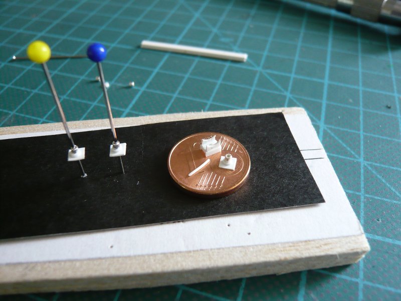
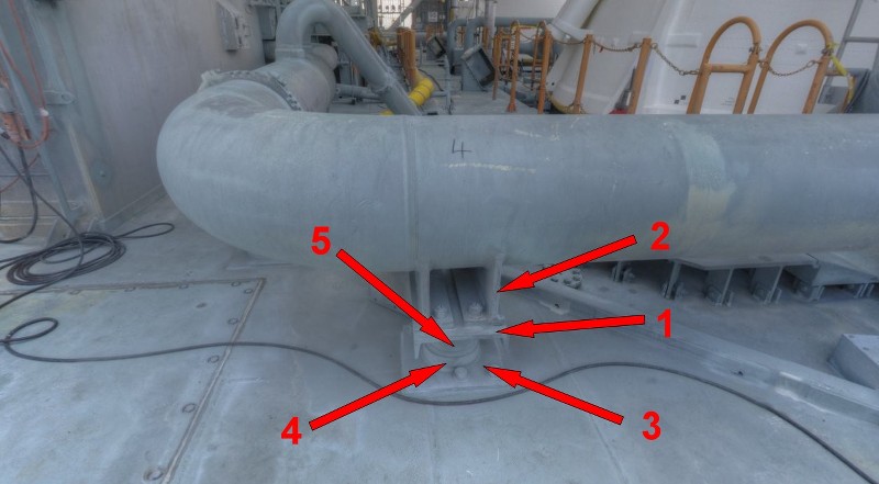
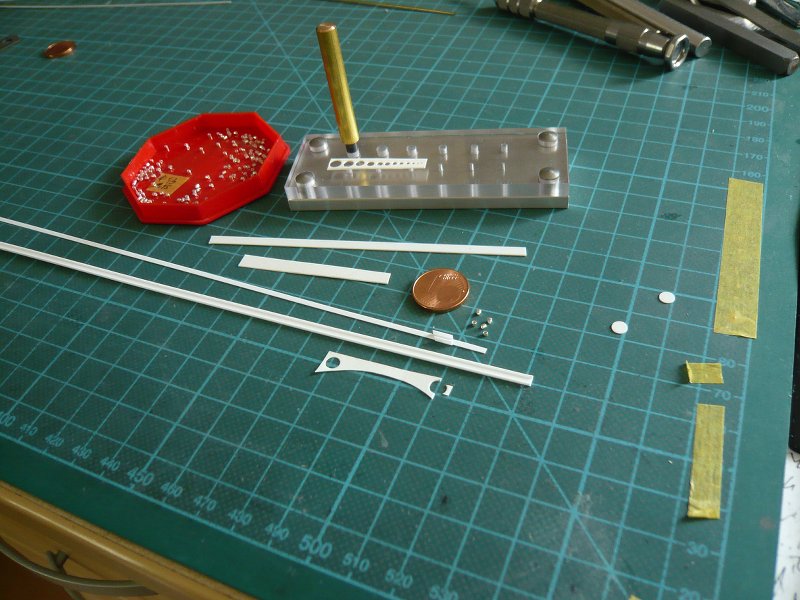
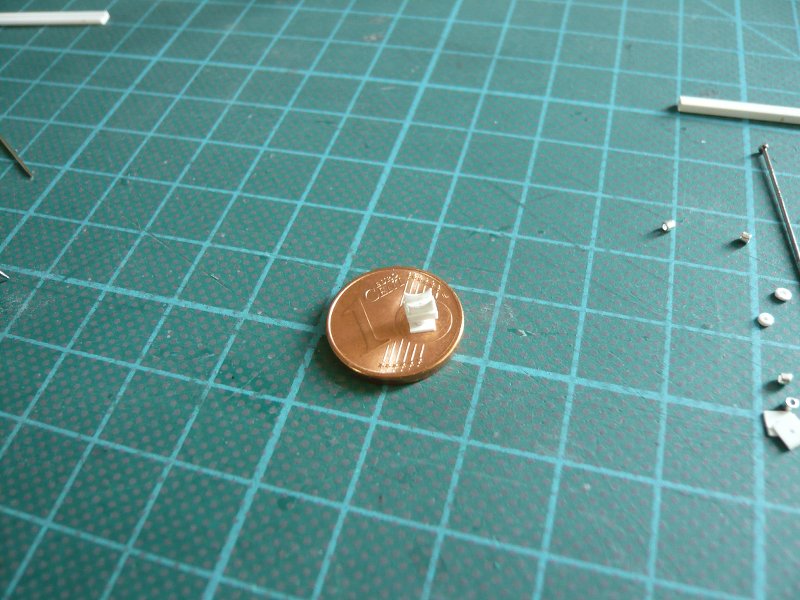
First to the preparation of the required items, as there would be the base plates (3 x 3 mm), feet (Ø 1,7 x 0,5 mm), the cover plates (2,5 x 3,5 x 0,25 mm) for the small sickles on which the pipes lie, and even sickles (0,25 mm). For this I’ve used my Punch&Die-Tool with 4 mm diameter as used already for the prototype.

In order to obtain possible a uniform height of 1 mm at the lowest point of the curve, I have used a corresponding spacers in the tool. And then it went on with punching, where you have to watch that one holds the punch vertically, since a small amount of play is present and the base plate is made of aluminum, which is not the last word.

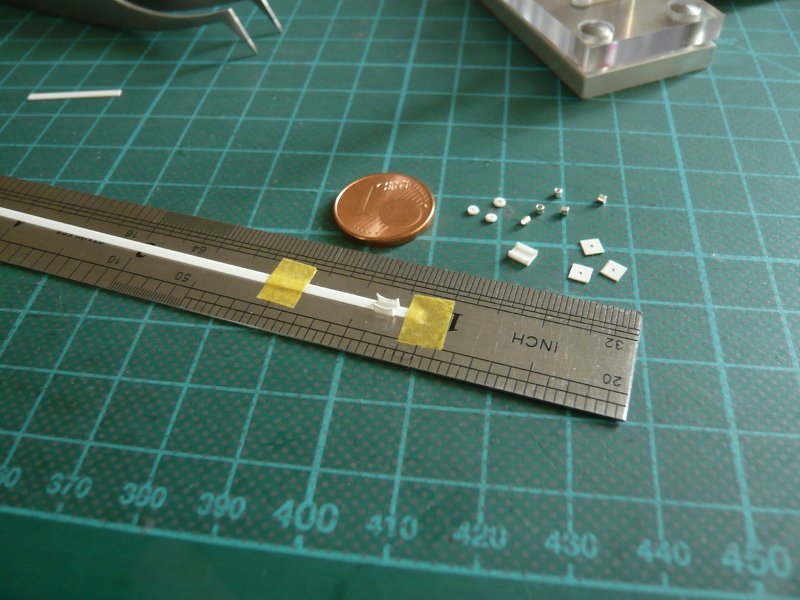
After that, I marked out in the strip 3 mm width of the sickles, which was quite a torture for the eyes, because this possible should be centered.

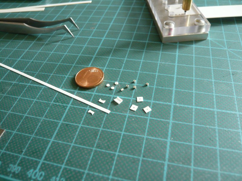
Then I have individually cut the sickles, but this is not quite succeeded, especially since there were a certain scattering of widths. Aside are the discs (Ø 1,7 mm) for the short legs and the base and upper plates.
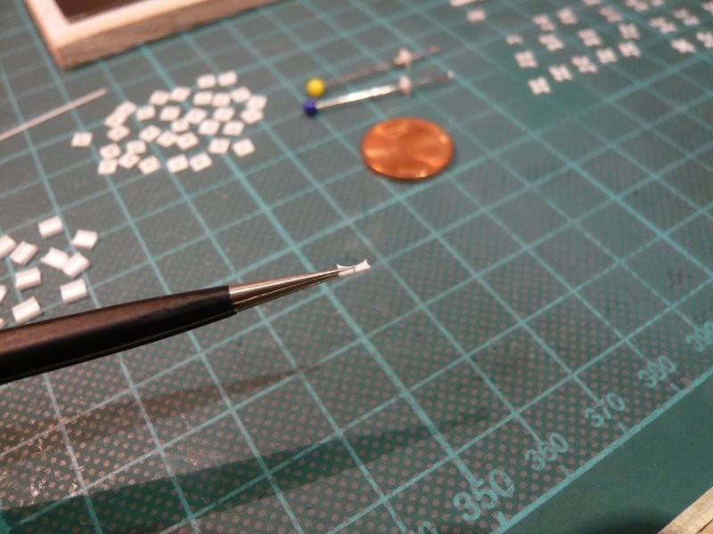
To make things worse, I have the sickles but not stored in pairs, so it was all messed up, what you can see here!

Although I have tried to sort the couples still halfway through laborious remeasuring, these couples were still relatively unequal, which would have meant complicated reworking. That’s why I’ve punched again a 2nd row and made it somewhat more accurately,

where I have tried starting from the middle to uniformly cut the couples on the ruler to 3 mm in length, as it were “hand-picked”.

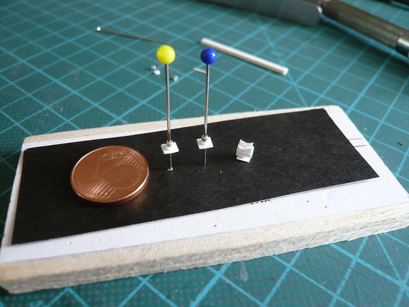
And thus the construction of the following supports was also more reproducible,

and thus also more evenly.

And so it went on, three type-2 support still missing,

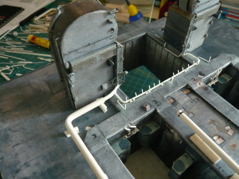
which followed immediately, so these six supports for the SRB Blast Shields finally are now complete.

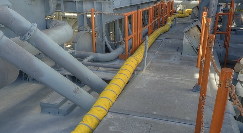
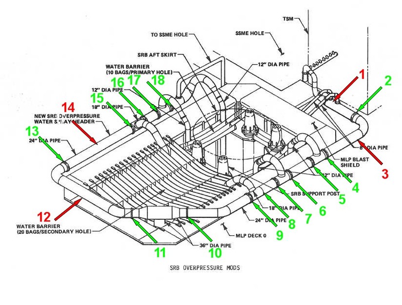
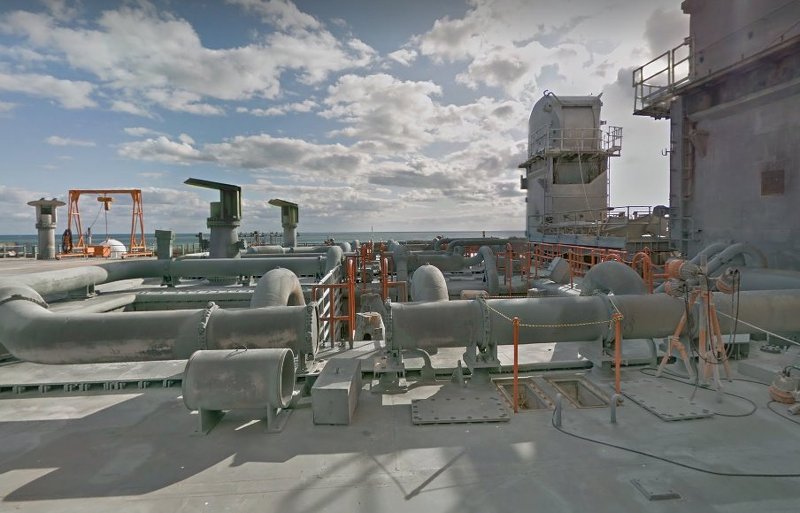
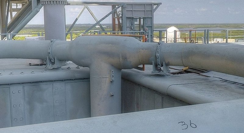
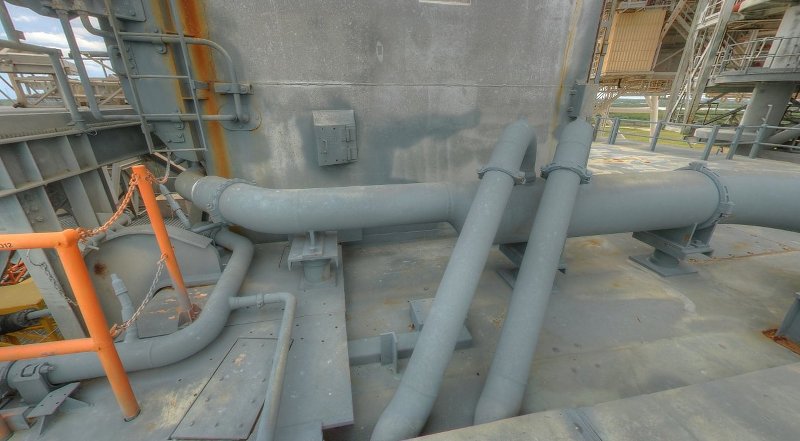
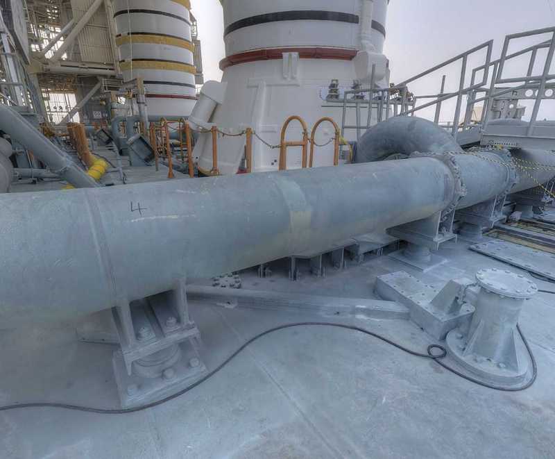
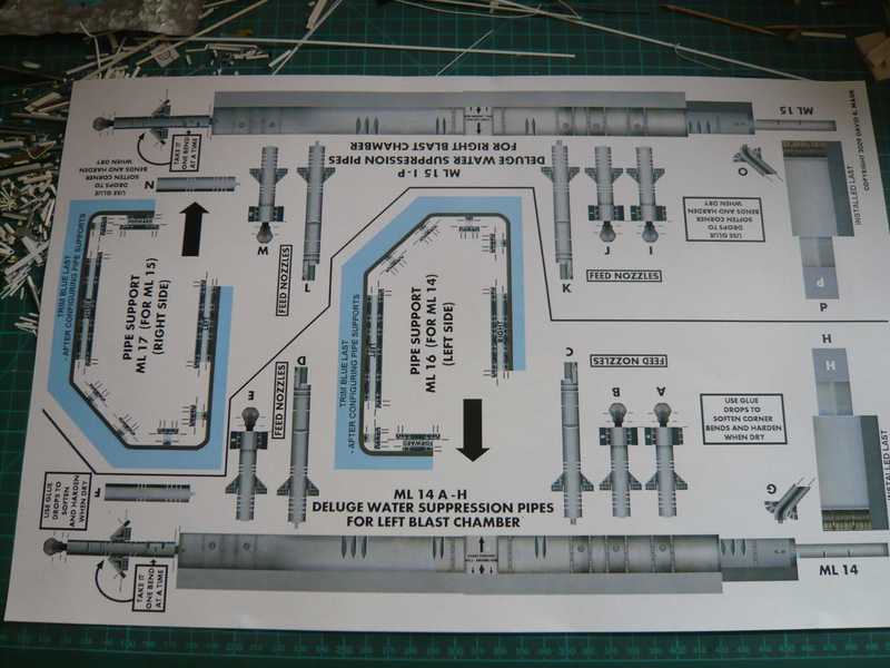
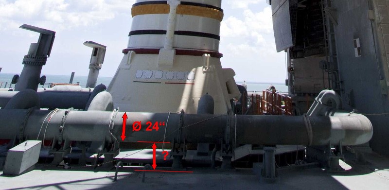
Now let’s go on with the small series of Type 1 Supports, which are arranged around the two SRB holes and carry the thick 24’’ SSWS line. Of which I need, after all, still 29 pieces, for what first had to be prepared a whole lot of small parts.

First, I have made the small sickles and this time I have acted differently. For that I have laid the sickle strip under a steel ruler, so that they overlap in each case 1,5 mm outwards, and then I have cut the sickle in each case 1,5 mm from the center behind the ruler edge that served as a stop for the cutter. And that worked really better and yielded 3 mm long sickles that have been straightened out a little here and there, if necessary.

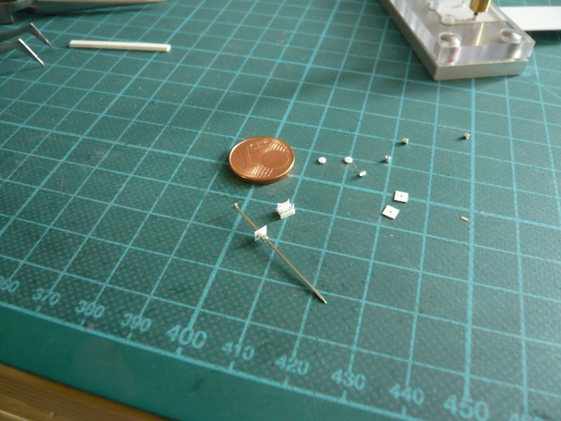
Then I’ve cut the 3 x 3 mm base plates and marked the centers for the holes, and then even punched the missing disks for the feet.

Now missing only the cover plates from Evergreen channels, which I’ve also cut by measuring with the steel ruler with 3,5 mm length, whereupon a safe stop has proven to be very helpful.

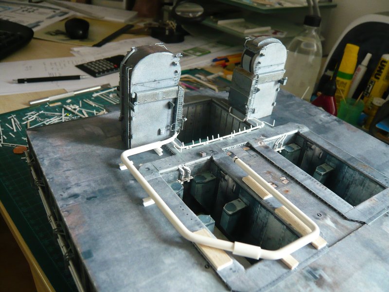
And so now everything is ready for the mounting of the supports, which will be the grand finale.

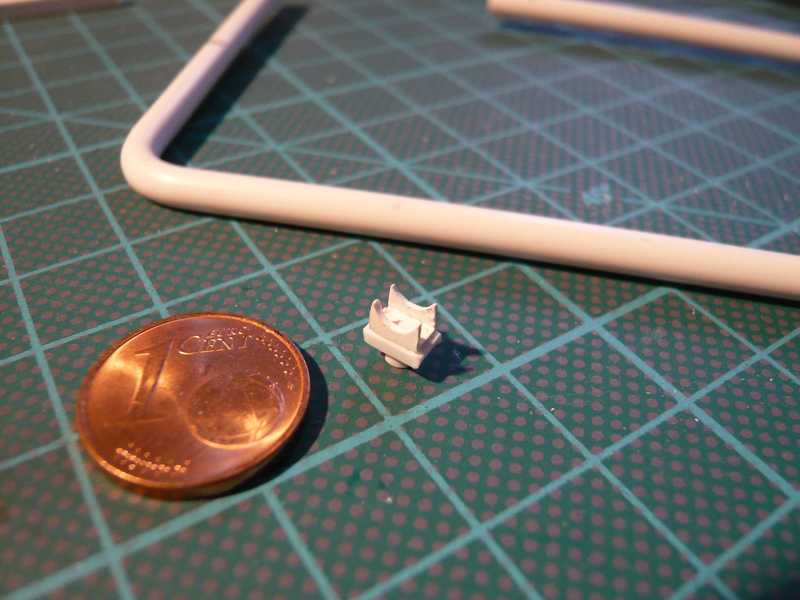
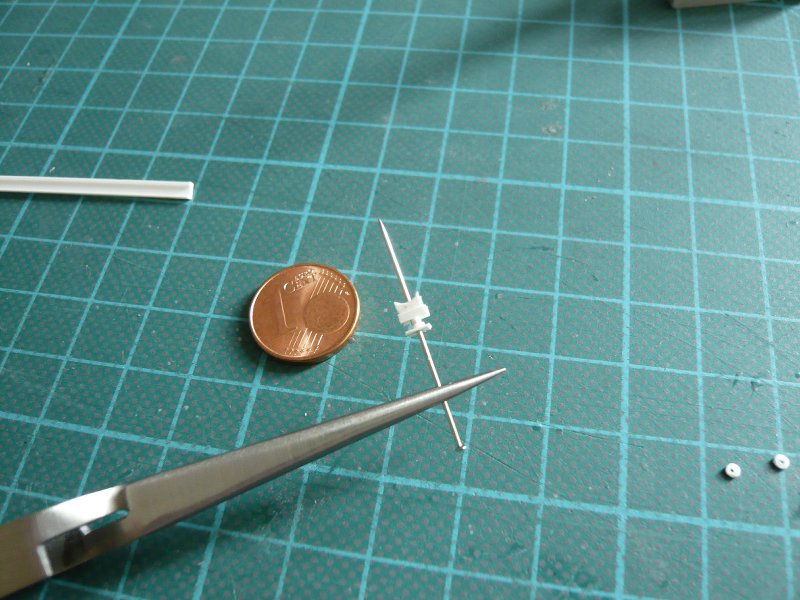
Yeah, that was a hard test of patience and pure stress for my old eyes, because I needed the head magnifying glass, and sneezing was strictly forbidden!

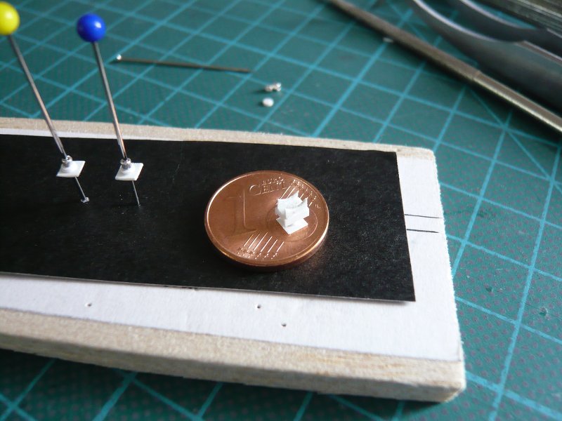
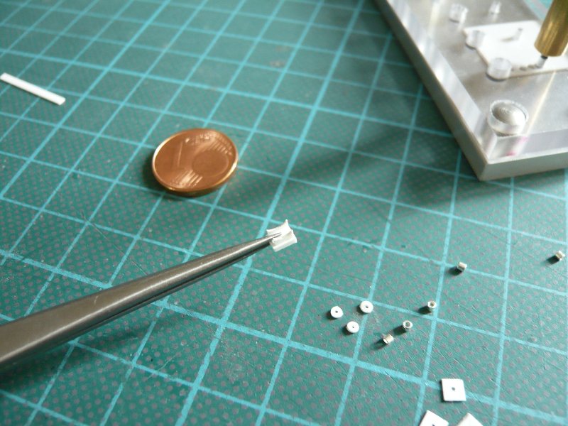
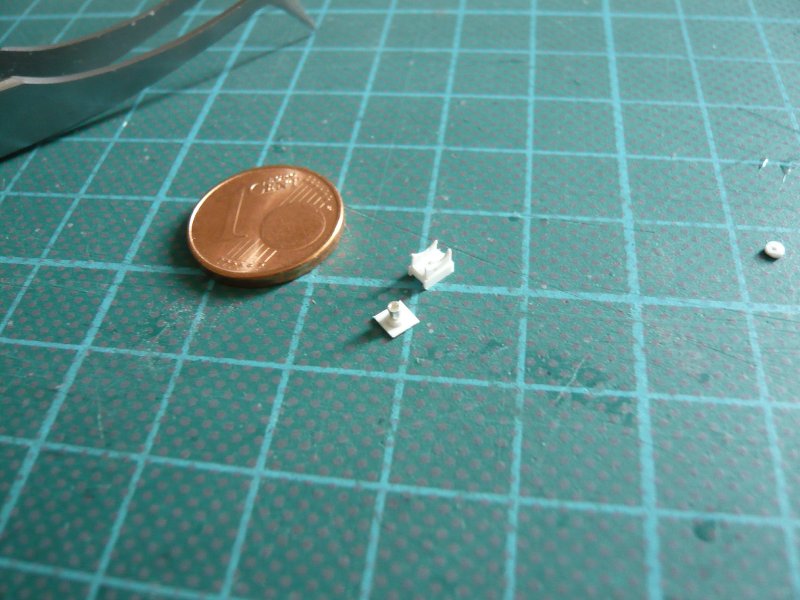
BTW, these parts are really tiny, and a few times I had to dive back down to the floor to look for the breakaways.

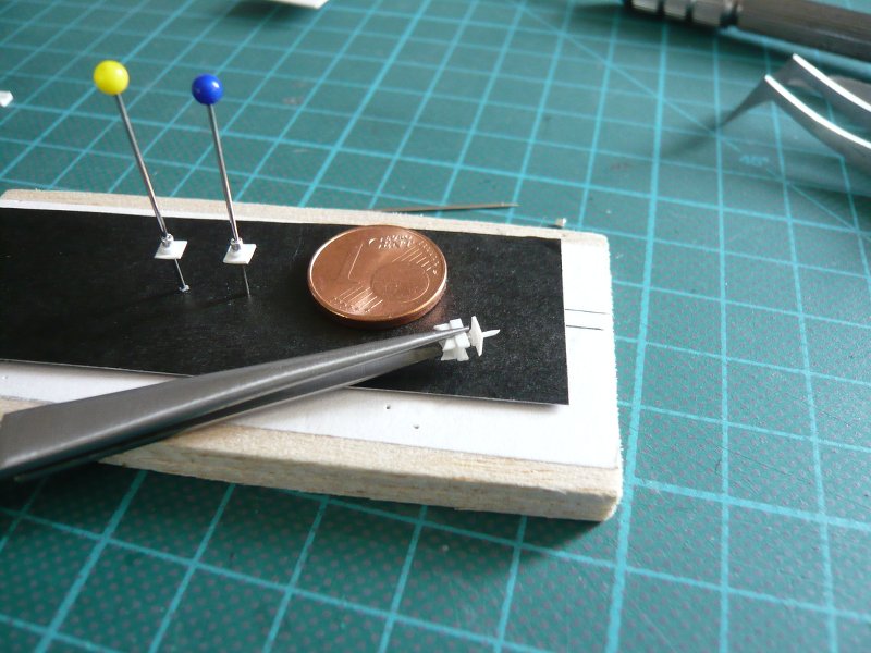
Only good thing I got myself some extra sharp tweezers,

otherwise you get these things hardly to grasp.

Let’s see how long that will take until all supports are finished, because those are a lot of hand grips, but there I have to struggle through, for better or worse …

And later all the tiny crazy clamping rings are waiting for me …

2 Likes

Hi all together,

let’s go to the next round of Support puzzles.

First had to be made the upper parts with the sickles. And that works best if you put the sickles between two steel rulers and aligns whereby its position is well secured. Then I glued the sickles with MEK.

Then the sickle plates were separated with the cutter.

Now it’s the lower parts turn, as usual, that is, center drilling the cover plates (Evergreen channel) and gluing the 0,5 mm rods, threading and gluing the foot-pearls and the pre-drilled discs and base plates.

The hardest part is then gluing the upper parts with the sickles on the cover plates of the lower parts, because that has to be relatively quickly aligned. And if that fits then, the finished support coming shortly in the slide caliper “vice” until the adhesive is fixed.

And here are the first finished Type 1 supports next to the six of Type 2. Although these are only three of 30 supports, but after all, the beginning is done.

Because I did not want to assemble a support to the other, but have prepared next all items, so bored all the plates and discs for the support rods centrically.

That was actually pure busywork, for which one needs angelic patience, which I still have, fortunately, but it was again considerable stress for the eyes, which is why some breaks had to be made!!!

Then I have glued all the support rods into the cover plates and threaded the foot-pearls,

and then placed and glued all foot discs.

Next it’s the base plates turn, but for now I’ve had enough …

1 Like

Hello friends,

it is still going on with the supports, now I have to stick all base plates.

Although this all looks very simple, but these many handles of threading and gluing the panels are grueling. Good thing I bought these pointed tweezers.

Thus, the filigree supports can be handed from one tweezer into the other for gluing the upper and lower parts.

When removing the center rod one must also be very careful so that nothing can be bent or even broken.

And thus 11 supports now at least are finished already.

For the remaining 19 supports I must however first glue the sickles, what will become stressful again.

But my magnifier is in any case already ready to hand.

But now let’s go to the final countdown, because I will compete the missing 19 supports, which must indeed come to an end.

My headset magnifier I have put on, and thus purely into the sickle turmoil, everything as usual according to the same procedure.

Thus, the first 12 sickle couples were done and now I need a new Evergreen Strip 0,25 x 1,5 mm.

And so the upper parts are finished (with a reserve part) and must be mounted only on the lower parts now.

For this, a steady hand and a stable basis now are in demand again, wherefore a cross tweezer is well suited.

Then just a droplet Revell Glue on the lower part, and with the pointed tweezer the upper part was placed and aligned immediately.

After that I glued around the upper part with MEK, better safe than sorry.

And now they are just waiting for the foot care,

and was then also soon done, as usual.

And so it is now done, and these 36 support from at least 282 parts are actually completed and I can make three crosses.

But do not worry, there are still other supports too, so it’s not.

These are, for example, these supports on the Blast Shields at the 18’’ branches running down here into the SRB holes.

3D-rotatable view of this area at nasatech

Source: nasatech.net

They look something different, otherwise it would be boring, and have again sickles to all abundance!

But now only the thick 24’’ pipes will come next from which these tubes branch off, and that means bending, all you’re worth …

1 Like

Wow buddy, you are on Fire. Just don’t listen to Smokey we need you to keep on jamming!

1 Like

Hi Mike,

yep, thanks to you I’ve caught a bit on fire surprisingly, so enjoy and be happy!

Posting by transferring my long NSF thread is not as time-consuming as I initially thought, and so I can simultaneously also update most of the old broken photo links in my NSF thread with current panorama links (nasatech.net), which gives benefit to all.

Hello folks,

before bending the 24’’ pipes, I once made a first attempt to indicate the tiny clamping rings.

And for that, I have first wound a few rings from Evergreen Strip 0,4 x 0,5 mm to a slightly thinner core (Ø 3 mm) and then blow-dried hot. The ring below the way, comes from a preliminary experiment with a profile 0,5 x 0,5 mm what me but already seems almost a bit too thick.

From the spiral I then separated me a few rings, one of which I have threaded to the thick pipe (Ø 4 mm) and then tentatively placed on three supports.

And so then it looks with three clamping rings.

From the optics, it certainly does not make a bad impression, I find. Maybe the screw connections might be indicated with a marker.

I almost think I should leave it at that, but I am still curious about your opinion.

Even a quick update to the clamping rings, with whom I have experimented a bit further.

Since I still wanted to try with the lead wire (Ø 0,5 mm), I had bent a few rings with Ø 4 mm to at least once to have the comparison to the strips.

At the marked points on the periphery the screw connections would now sitting with about 0,7 mm in length. To indicate this, I thought now to be able to press the gaps a little flat, but unfortunately that did not work.

Therefore here again for comparison three clamping rings, from left to right the lead wire 0,5 mm, a 0,25 x 0,5 mm strip and a 0,4 x 0,5 mm strip.

In my view, the 0,25 x 0,5 mm strip in the middle could almost be enough, right?
Maybe one could still indicate the screw connections, what I’m going to try yet.

And then we’ll see …

2 Likes

Hello everybody,

I have tried to indicate the screw connections of the clamping rings, and it was again a tricky thing with some surprises.

After I had made a winding off from the circumference of the 4 mm pipe with the intervals for the six screw connections, I have cut first 0,7 mm long pieces from an Evergreen Strip 0,25 x 0,5 mm. And as one can see, this is sometimes not as easy as it looks to produce these particles in a uniform length, but for the first experiments should that be enough.

The next little problem was then the bonding of these tiny parts on the Strip. First, I have with the needle in the left hand touched the parts and have deposed and detained as accurately as possible on the mark. And then I have brushed them with the right hand with MEK, which they sit relatively quickly fixed. And also for this promotion you need a steady hand, so nothing slips.

The gluing of the strip on the Pipe I have tried before, and it is advisable to first to glue only the starting point, which I have used CA, so that the strip is firmly seated.

But because the handling of the needle is such a windy thing, with the next ring I have tested yet another technique with a pointed tweezer, with which one can position the particles somewhat safer and more accurate and also hold better. And then also looked already more evenly.

And for the third ring I have used a 0,3 mm rod for the screw connections, but the central positioning of the thin round snippets with the tweezer was something trickier and has not become sufficiently uniform.

When I wanted to glue to the first ring after adhesion with CA on the pipe with MEK, there was a surprise, because the ring is broken suddenly, what has surprised me already. This is probably because of the curved under tension ring instantly softens on contact with the MEK brush and immediately breaks because that’s then happened again and again.

Therefore, I have glued the next ring with CA,

what has then also worked well and looks fairly decent.

And here you can see now the comparison of the clamping rings on the supports, left the already known type of 0,5 x 0,5 mm strip and the two right from 0,25 x 0,5 mm strips, without and with indicated screw connections.

This was the first attempt, and therefore I want to do no better or worse to, than it is. But that’s quite an effort taking a realistic view.

The screw connections one could still carefully slightly round, if they hold, what would surely look even better.

Now I’m curious first of all on your opinion, no matter how it may turn out.

3 Likes

Ok, no answer is also an answer, then let’s go on.

But to be honest, I’m torn back and forth and not quite in peace with myself, which is now the most viable solution.

I have just recounted again that would namely be 28 supports with 168 of these cute clamping rings, and this affair I imagine really creepy, especially since it also brutally would be for the eyes and would take quite a while.

But what kind of crazy things I’ve not done already …

Possibly I’m using at the end but still David Maier’s paper templates and glue the therein indicated clamping rings on the 0,25 x 0,5 mm strips that do not even look so bad for my taste.

But I can leave everything first of all to rest, because now I can amuse with the bending of the 24’’ lines, and previously the clamping rings are not needed.

1 Like