So very good… It’s great to watch you engineer this … The rings look great… I actually thought the middle one looked best to the eye, but that’s just my opinion… The screw blocks look very very fiddly… Top marks for doing them, and the whole part looks so much better… Great work
Thanks John for your opinion regarding the tricky clamping rings. ![]()
But I will first come back to the bending of the SSWS 24’’ ring lines, which I had already briefly started at the beginning, what will then be completed by the clamping rings at the end. 

1 Like
Hello everybody,
before the bending of the second ring line I still wanted to check their position on the MLP, here initially on the sketch, to which it fits very well. 
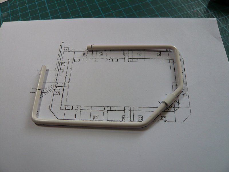
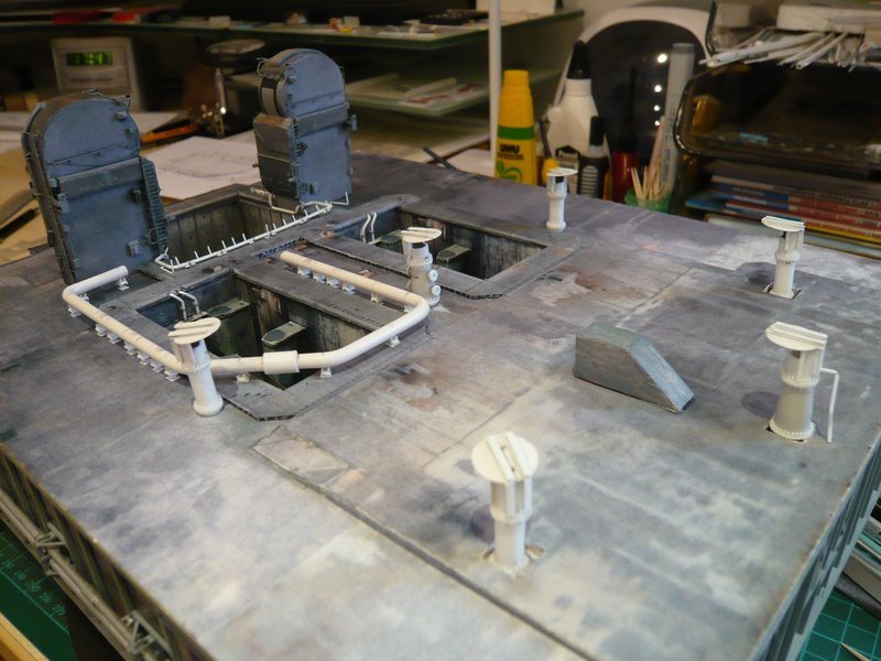
And here the positions of all 20 Pipe Supports are now marked,

whereby the 18 supports for 24’’ Ring line (Ø 4 mm) are already finished and waiting for the test, of which there are both some with clamping rings (green) as also without (red).
Support No. 1 (red) supports the 16’’ rejuvenation (Ø 2,5 mm) immediately in front of the LH2-TSM and is constructed a bit easier.
3D-rotatable view of this area at nasatech

Source: nasatech.net
And No. 6 (red) is this longer support below the 9’’ Pipe (Ø 1,4 mm) which is running into the SSME chamber.
3D-rotatable view of this area at nasatech
Source: nasatech.net
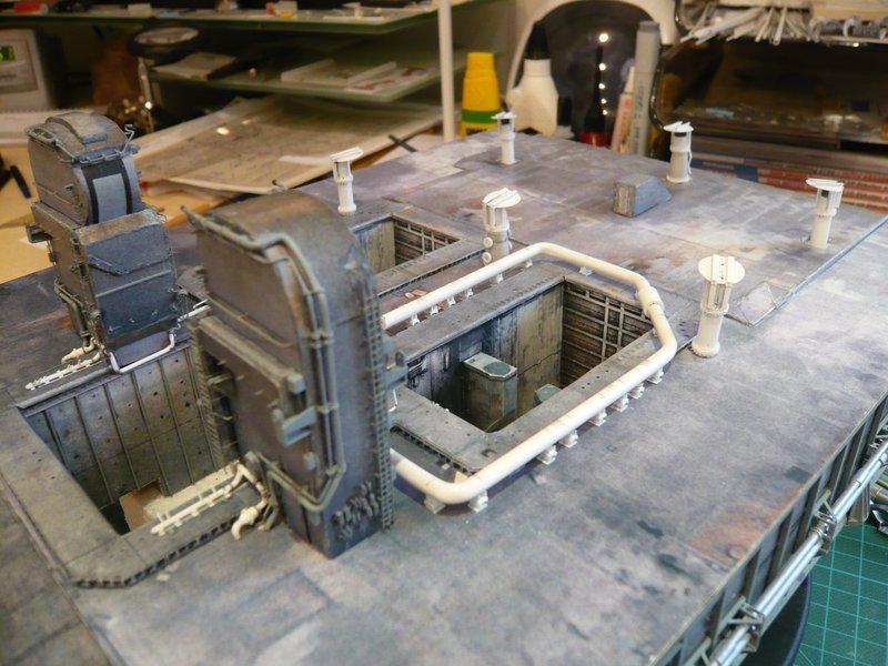
Here I have the ring line tentatively set on the 18 supports, whereby Nos. 1 and 6 (red) are missing.

But that is not enough, because for the holders of the arcuate outlets of both ring lines into the SRB-shafts are needed in each case 12 of these supports (in the sketch blue) which are standing on the Blast Shields. 
3D-rotatable view of this area at nasatech
Source: nasatech.net
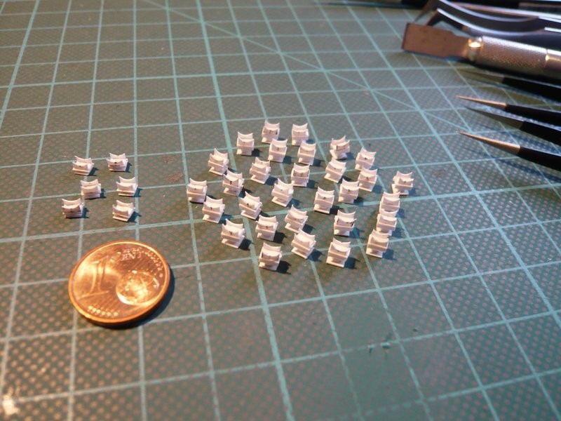
They have a slightly different substructure, but in any case I need 24 of these tiny sickle-shaped supports, I’m looking forward already. ![]()
And here I also have arranged the six pretty Rainbirds to complete the picture, whose scratch building I will show later in more detail.
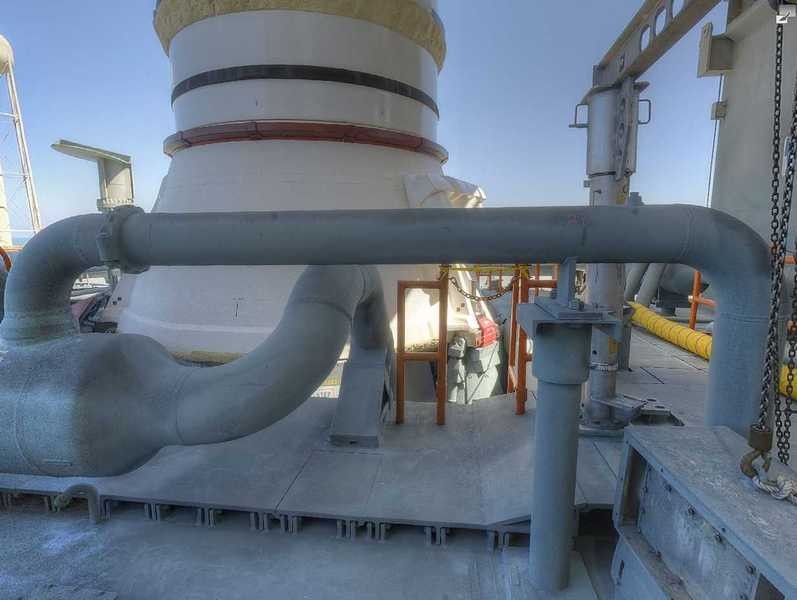
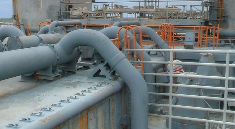
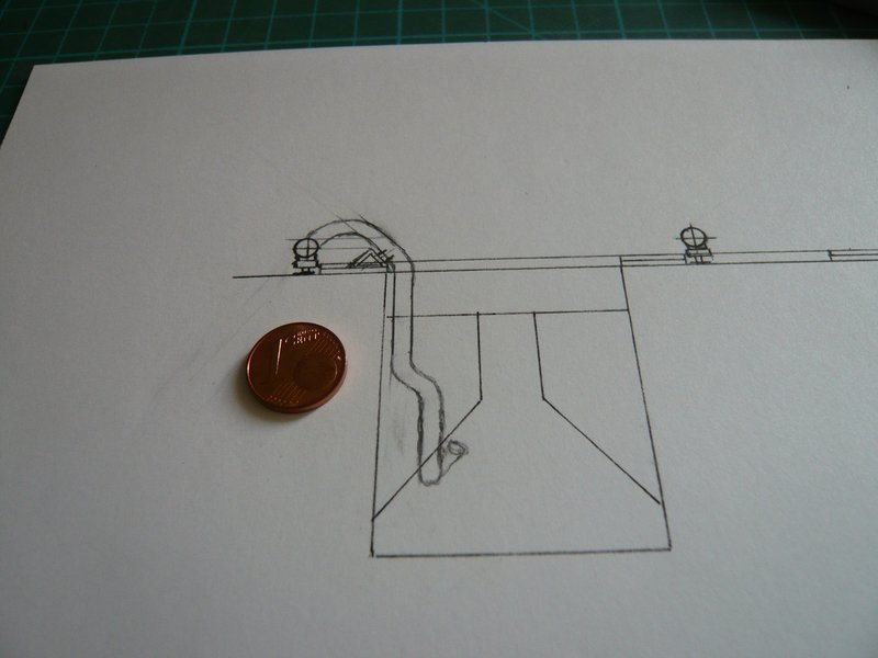
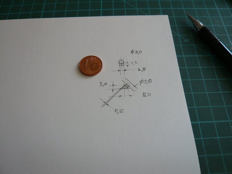
And so now follow the four rear 18’’ outlets (Ø 3 mm), for which I have drawn this sketch.
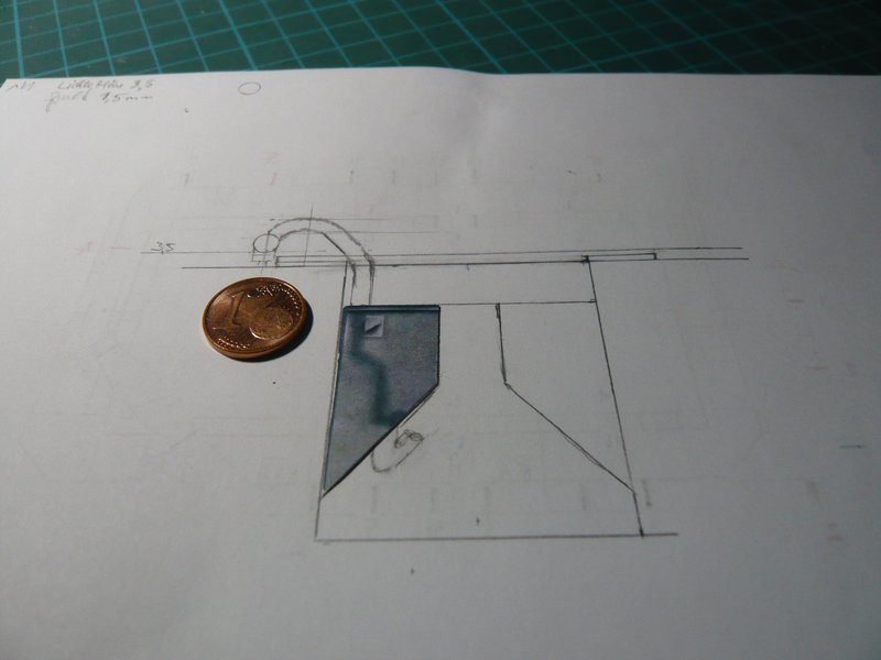
These are admittedly not tapered, but five-fold bent, and are ending below the SRB Supports.
3D-rotatable view of this area at nasatech
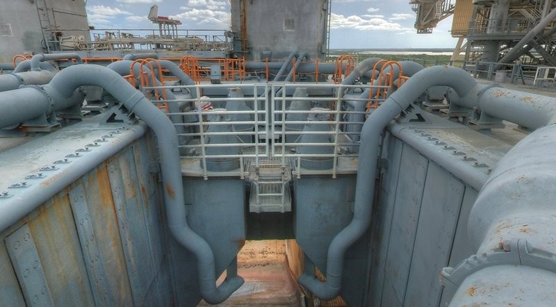
Source: nasatech.net
And because I need four of these tortuous “earthworms”, a balsa template will be worthwhile again.

2 Likes
Hello everybody,
let’s get started with the first act of the new bending orgy. 
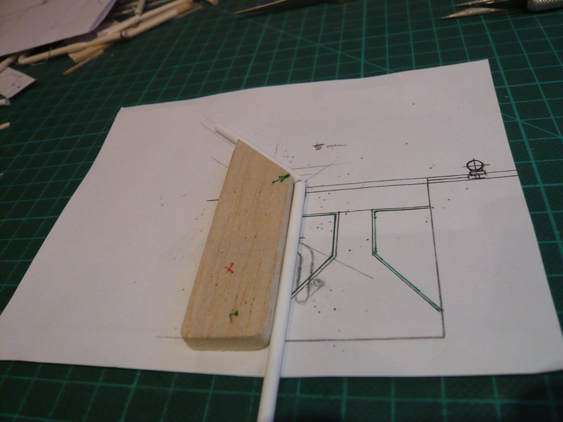
ere once again the sketch of the 18’’ outlet as a basis for the template, in which I have drawn already the pipe support on the SRB-Blast Shield, to this but later.
This time, the bending process is not as easy as with the ring line, in which it only once went all-around. 
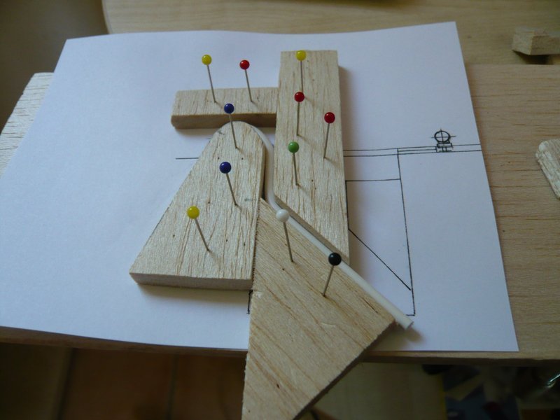
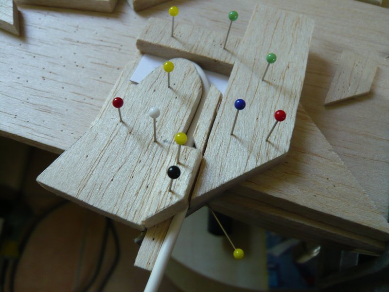
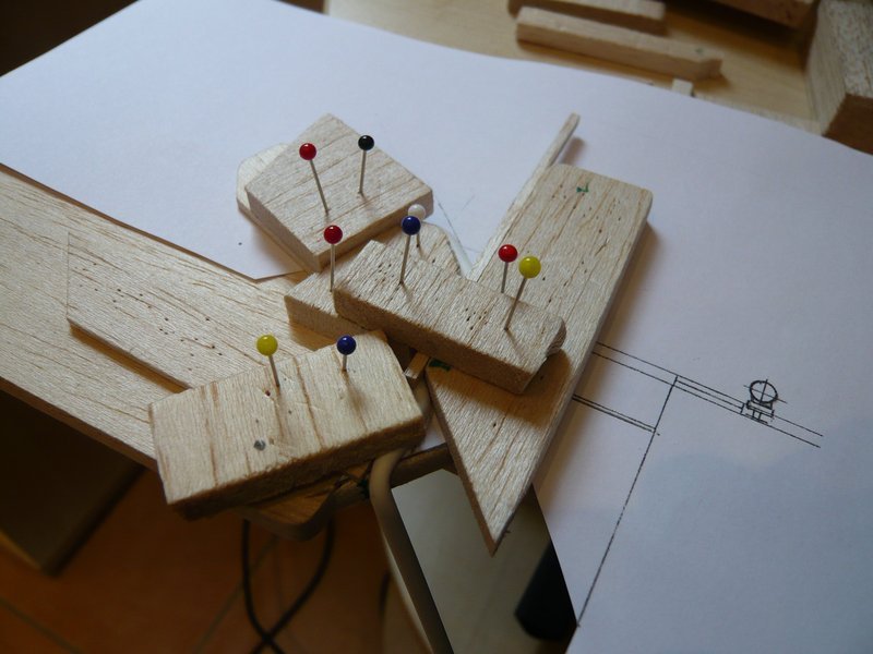
Therefore, this template (left in the image) can be used only for the upper rounding and the subsequent outlet, whereby a consistent holding is very important.
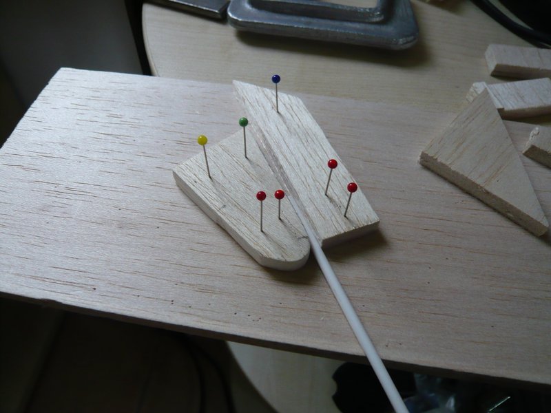
And during the stepwise bending then the hot air gun takes action.
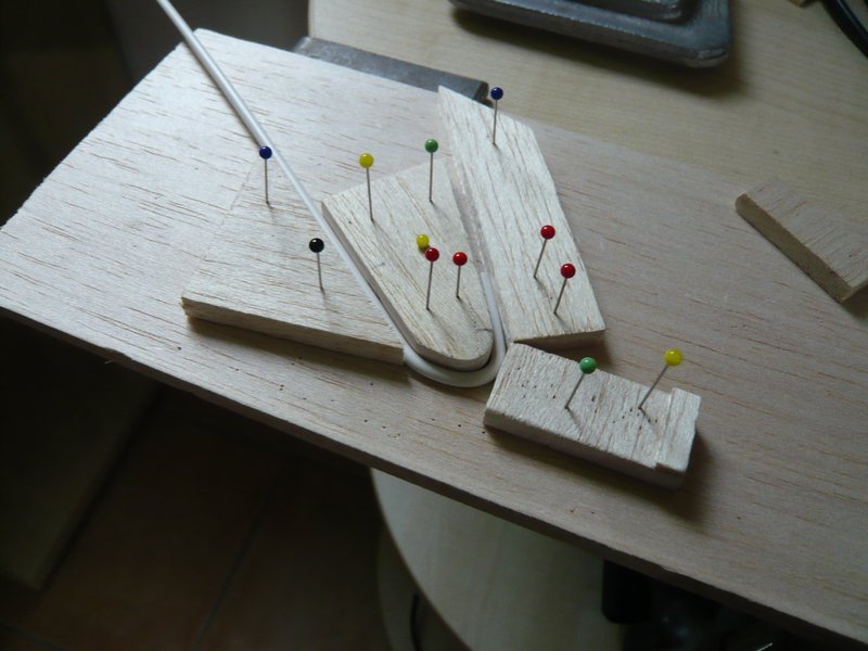
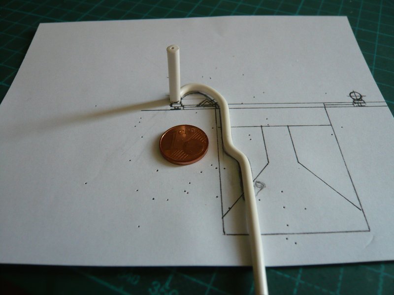
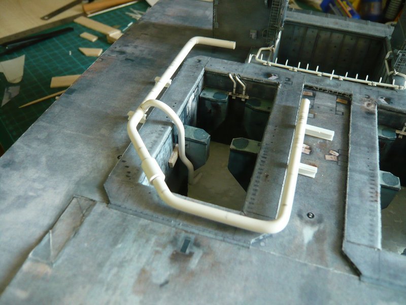
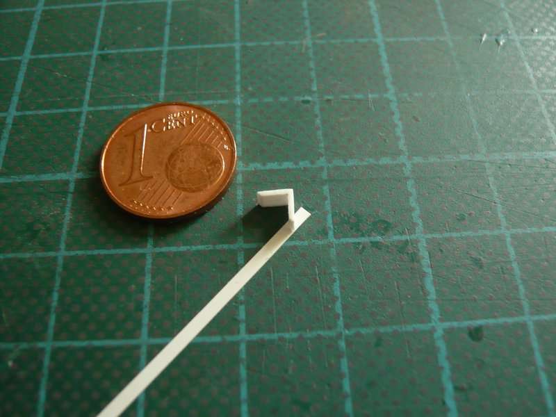
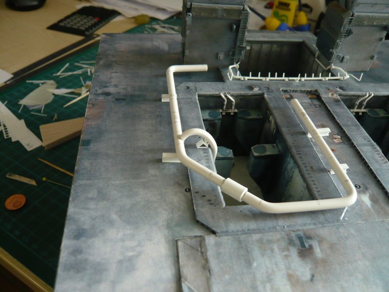
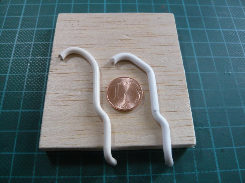
This is the intermediate result, which seems to be quite useful, only the short piece after the upper arch should actually be still a bit flatter, but it could not be aligned close enough. But it became probably something too hot for my fingers. ![]()
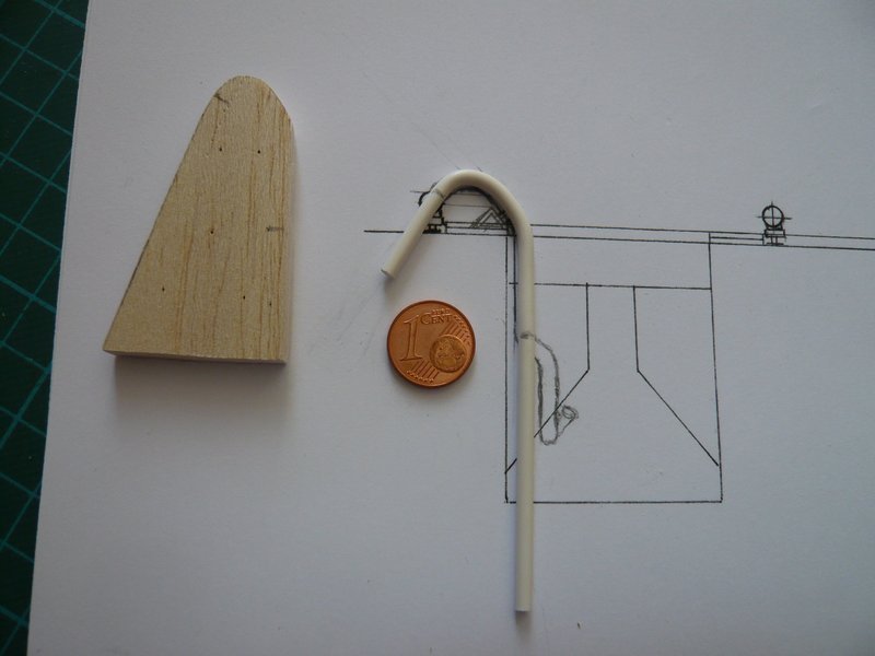
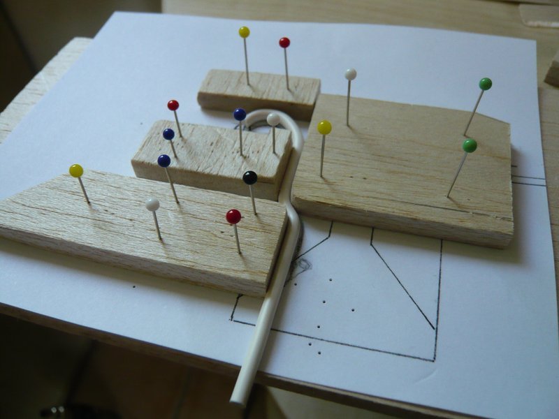
Now the overhang part can be separated and then the junction be rounded.
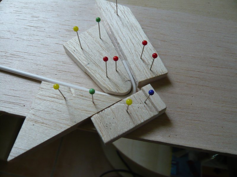
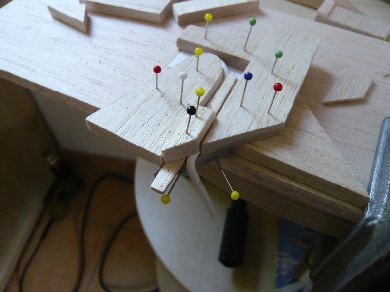
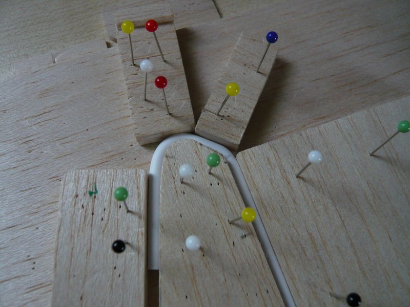
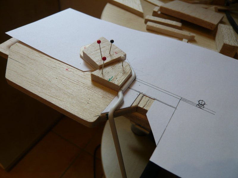
In order to bend the following short slant it must be re-clamped.
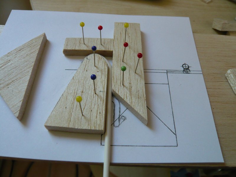
For this the rod must be aligned with the balsa triangle narrow to the slant. After fixation of the triangle with the pins it must be blow-dried again, and only after cooling, the clamps can be removed.
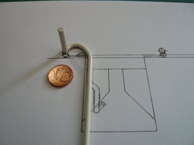
Thereafter, the rod should should fit snugly and not splay back again. And then follows the second bending downwards,
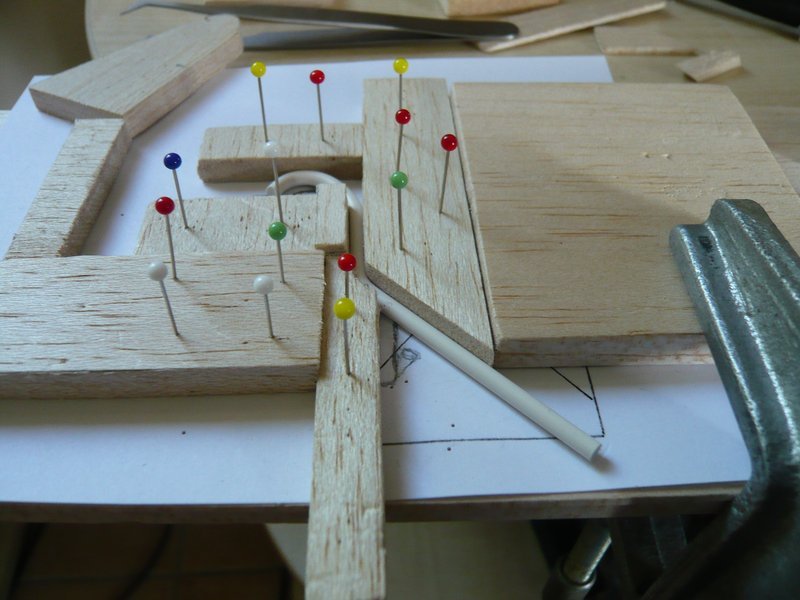
whereto I yet again have re-clamped and used a more stable board with slanted corner.
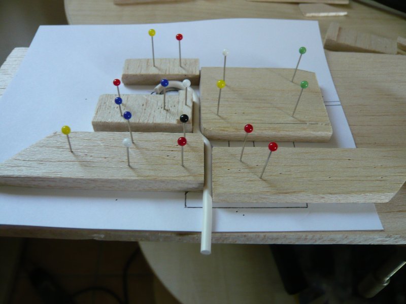
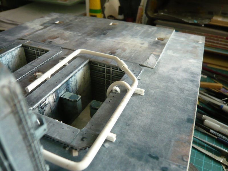
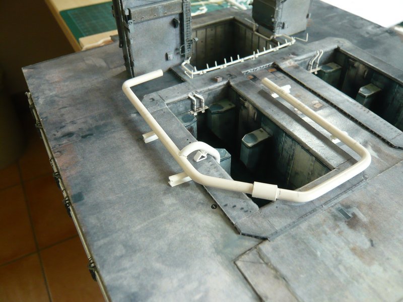
And this is the preliminary result, which can be quite impressive. ![]()
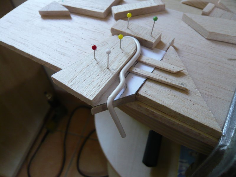
Now only the final bending til below the SRB support is missing, for which I still have to determine the distances and dimensions.
Source: nasatech.net
And now a short outlook at the initially mentioned pipe supports under the outlets.
Source: nasatech.net
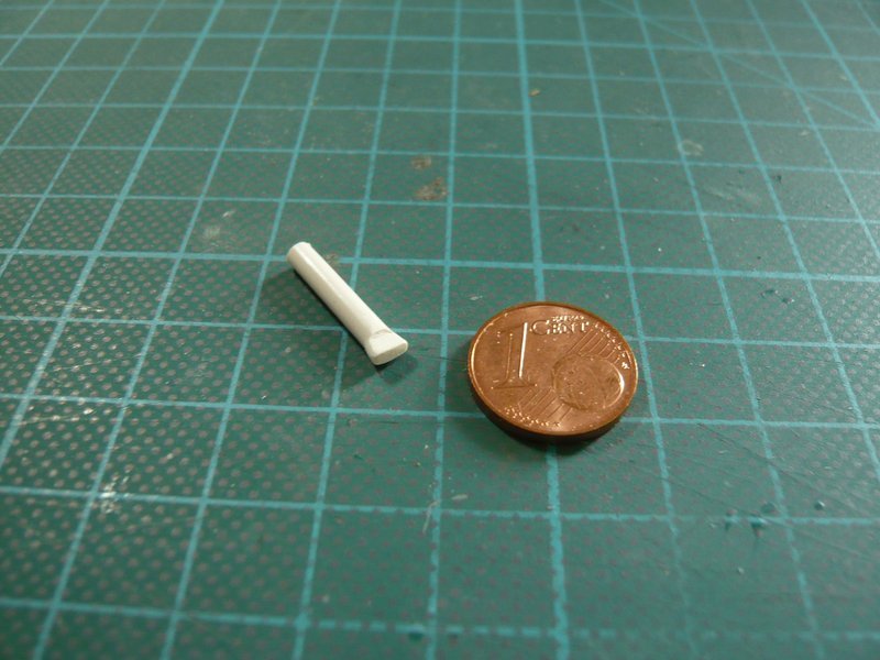
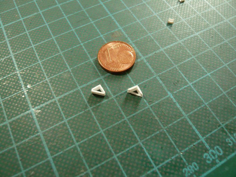
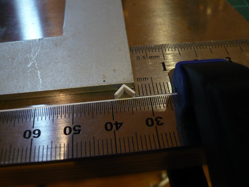
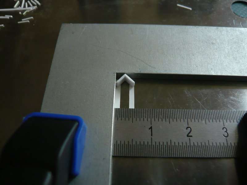
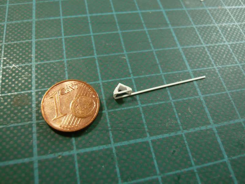
In this image all looks again relatively easy, the triangular base as well as the sickle shaped brackets, similar to those at the supports for the 24’’ ring line. But if one now outlines the real proportions in model scale, then this part shrinks considerably. ![]()
And this should be enough for today.
4 Likes
I absolutely love these jigs you make for the pipe bending … Genius ![]()
![]()
1 Like
Thanks John for your nice compliments. ![]()
Yep, that was a really creative phase by me 7 years ago,  always still a bending more …
 ![]()
Working two-dimensional in one plane, everything was still relatively easy, but just with the transition into three-dimensionality all jigs became crazier and more difficult to realize. ![]()
But then I won’t give up, cost what it may.
Where there is a will, there’s a way!
2 Likes
Just catching up here Manfred. Those images look great. The detail is getting better by the day. Do you ever sleep? I would be up all night doing this tiny detail and still not be able to get done what you doing. Top notch my friend. ![]()
1 Like
Thanks Mike for your kind words, ![]()
Of course I sleep, just like you, but often not enough when I go to bed at 1:30 a.m. because I’m posting new progress for you.
 Good Night & Nice Dreams
Skill comes with practice! - No pain, no gain!
2 Likes
No, no, no, no…all I know is…

2 Likes
Hi Mike,
You don’t need any understatement. Trial and error, or still better success! ![]()
![]()
Hello everybody,
I will tell you briefly what else happens, not much, but still gave it to me some new impressions and insights.
The last bending of the 18’’ outlet obliquely inwards til under the SRB Support was missing still, for which the outlet again was firmly clamped in with balsa boards,
and was then bent in the hot air stream.
Then I have the bent outlet temporarily hanged in the chamber and viewed from all sides, as well as compared with the reference pictures, whereby I have noticed a few things.
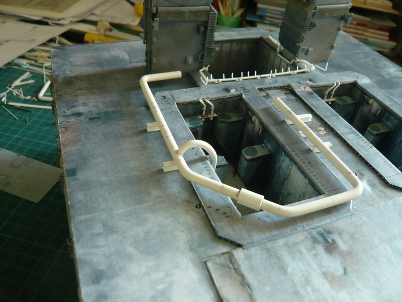
Thereby the 18’’ outlet (Ø 3 mm) optically seems to be a bit too small compared to the 24’’ ring line (Ø 4 mm), which is why I still will do a second attempt with an Evergreen rod Ø 3,2 mm. Sometimes making a few tenths already something. Furthermore the top arc is to me altogether a little bit too round, because the slant to the vertical part is too little marked. 
And then the last bending til below the slant of the SRB support lies a little too far below, namely further than it looks in the picture, what I’ll check in more detail.
Finally, I have tried to scratch the outlet opening at the end of the line,
3D-rotatable view of this area at nasatech
Source: nasatech.net
whereto I have simply flattened the 3 mm rod with pliers, which would almost suffice already.
Okay, that’s all not earth-shattering, but maybe I could make it still a bit better.
1 Like
And for these pipe supports at the rear 18’’ outlets I have now tried some variants.
3D-rotatable view of this area at nasatech
Source: nasatech.net
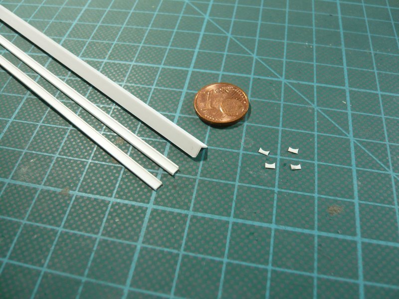
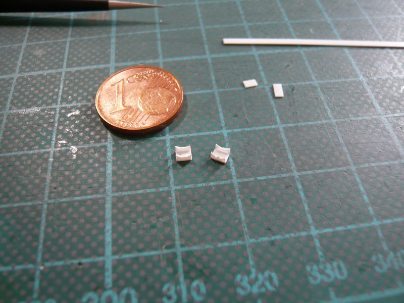
Here are some Evergreen profiles that come into question. And these are from top to bottom a 4 mm angle profile, a 2,5 mm channel, and the same profile, in which I have sanded the lateral webs in the front region down to a profile height of 0,75mm.
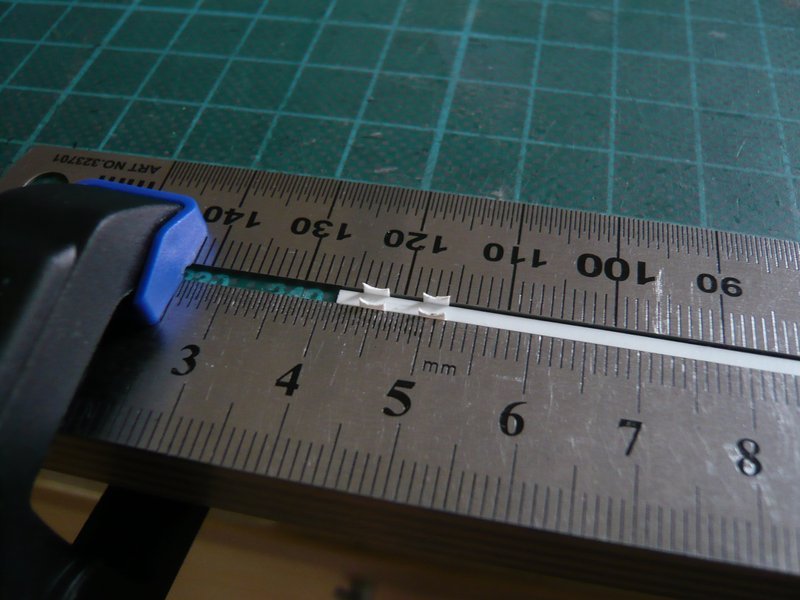
To the right already the first four sickles for pipe holders of the upper parts are ready,
which I have fastened again in proven manner and have glued with MEK.
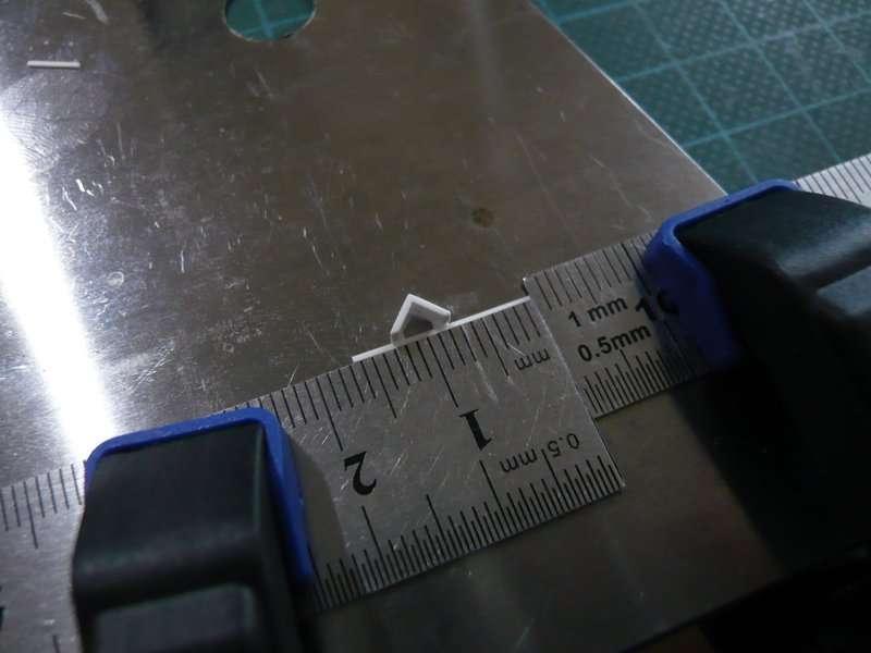
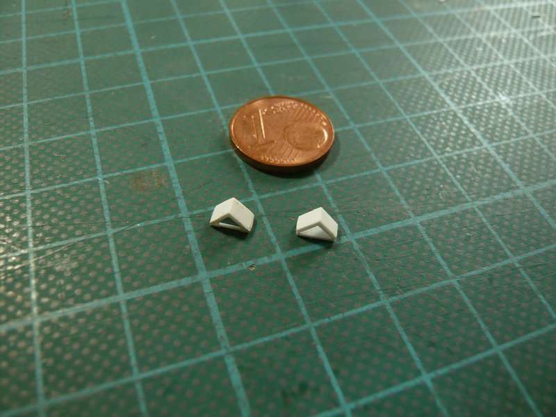
And this is initially the easiest variant for the triangular substructure, whereto I have glued a 4 mm Evergreen-angle onto a 0,5 mm base plate.
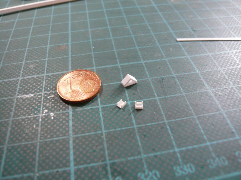

But as one can see in the picture, the substructures are actually open at the bottom and have two thin base struts.
3D-rotatable view of this area at nasatech

Source: nasatech.net
Therefore I wanted to try a downwardly open variant, and used the sanded down 2,5 mm Evergreen Channel. But therefor one has to deal immediately with miter cuts, which also must have the same length, what is easier said than done.
And then the slanted struts (0,25 x 0,75 mm) have to be glued, but this one is still too wide and is located too far up, since the angle must be sitting on the struts. Therefore, an Evergreen-Strip certainly should be better suited 0,25 x 0,5 mm.
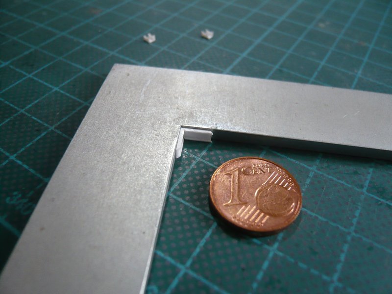
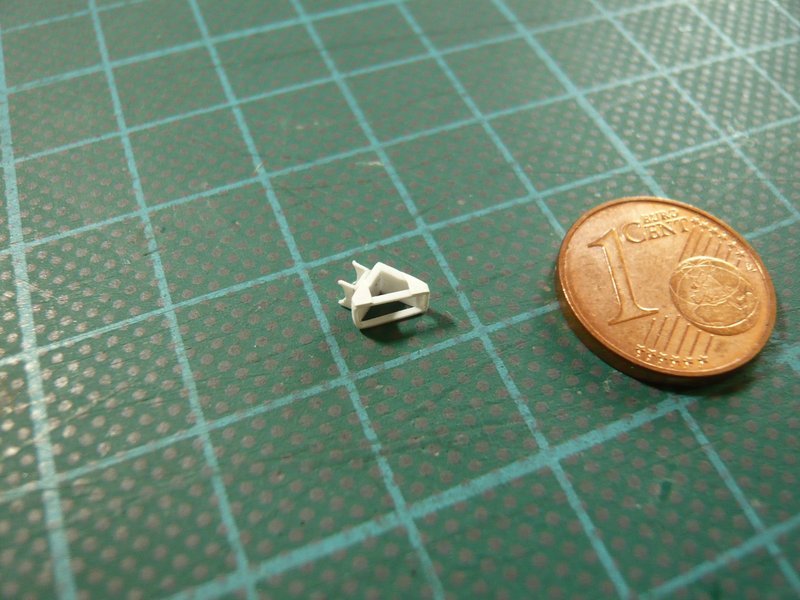
So I’ve been thinking about another possibility and have chosen this strip 0,25 x 0,5 mm for building of a thin frame.

But after the first two frame strips were glued laboriously separately, I had to realize that this could be no viable method obviously. 
But then I benefited that this thin strip can actually bend without breaking, which I have previously already experienced with similar strips.

So I have removed these two strips and started a new attempt, in which I wanted to try to bend the strip into a small frame and to glue under the angle. Although these are only tiny contact points, but with MEK it works well, but if they can withstand the bending, remains to be seen. ![]()

And with this bending it should be continued next, thereby I should benefit from another detail of these supports, which I previously wanted to leave off.
3 Likes
Hi friends,
first we need to talk about a silly thing happening to my linked nasatech.net panorama views, wherewith KitMaker has any problem, I don’t not why? ![]()
After my post yesterday, I double-checked the links, which worked with no error message.
When I wanted to open it now, I get this error message
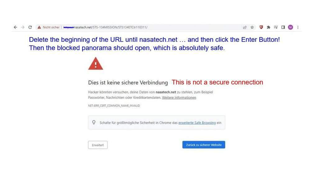
that this is not a secure connection and therefore is blocked, which I can’t explain.
Maybe an admin can explain it, otherwise I can omit these panorama links too which means less effort for me and would be the simplest solution. That should be only a bonus from me to you.
But I can also continue to link it as before. Then there is the following simple solution for you in order to see the great panorama views.
Delete in the opened website the beginning of the URL until nasatech.net … and then click the Enter Button! Then the blocked panorama view should be opened, which is absolutely safe too.
Rely on my friend John O’Connor, who has created a lot of overwhelming panoramic views of all the Lauch Complex 39A hardware on his websites, for which he has photo permission from NASA!
Hi everybody,
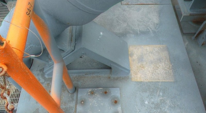
and thus to this support detail, although this every now and then was caught in my eye, but it was not previously appeared as so important to me and I therefore omit wanted. That are these welded stiffening plates, which are barely visible in these not linked nasatech.net images of MLP-3.
Source: NASA
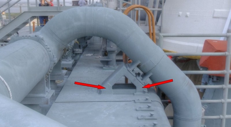
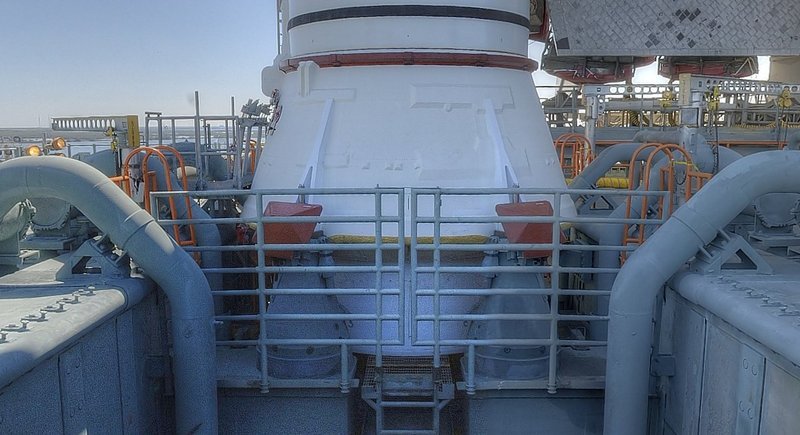
In this photo from the MLP-2 one can see them more clearly, but also recognizes that there are obviously different forms. ![]()
Source: NASA
And these plates vary actually from MLP to MLP and are themselves neither uniformly on a MLP on all supports, nor on the front and back of individual supports, what can be quite confusing at the moment.
Therefore, I have henceforth concentrated myself only on images from the MLP 2, and there are also supports (the left 18’’ outlet) mounted on the top which still have an additional third stiffening plate.
Notice this next nasatech.net image which is linked again.
3D-rotatable view of this area at nasatech
Source: nasatech.net
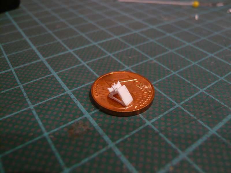
And these plates I have availed for bonding a filigree frame of a 0,25 x 0,5 mm strip, because without one, though minimal, bearing surface it would be probably become nothing.
For the plates at the base I have cut narrow strips of 0,1 mm Styrene and glued it onto the angle with MEK.


And on these strips, I have glued the frame strip (0,25 x 0,5 mm),
then I’ve cut the overhanging strips. And then, at the corner followed the first bend and bonding of the frame on the narrow side, etc. all around.

One just have to pay attention to solid support surfaces, then it will work, even if it is rather fidgety. ![]()
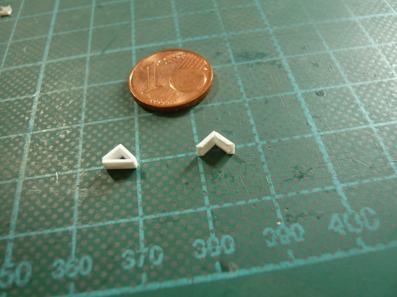
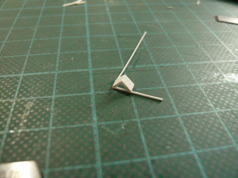
After this also the second Support variant with an open bottom was finished and is presented here with the first variant. ![]() Now may be glued even the plates on the back.
Now may be glued even the plates on the back.
And now also the top part with the sickles was glued, thus the support would be completed.
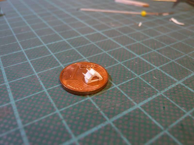
And the fitting of the first support on the MLP should not be missing.
Accordingly, I will stay with this variant, since the envisaged channel variant therefore has become superfluous.
3 Likes
16 posts were merged into an existing topic: HTTP vs. HTTPS image links
Hello friends,
as I had already indicated, with the first bend test of the 18’’ outlet I was not completely satisfied, because the upper bend downwards to the kink total still was too round what was due to the template.

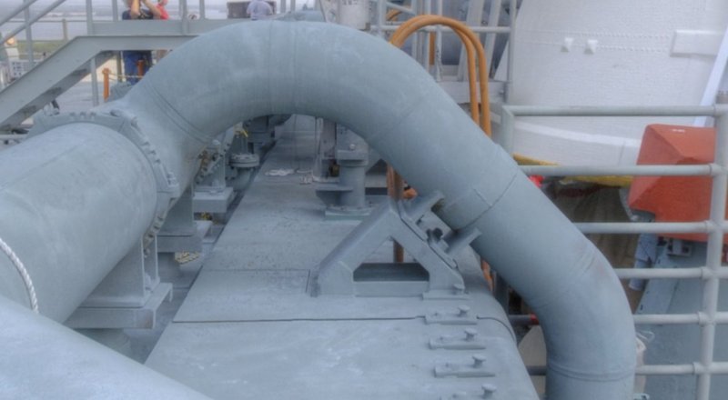
In reality, the piece above the support is until to the edge of the Blast Shield but straight, as one can see here.

Source: nasatech.net
In the meantime I’ve also bought Evergreen Rods Ø 3,2mm.
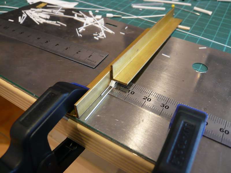
In order to get the bend at the second time right, I have bevelled the slight arc of the template, as well as choosen a different bending sequence and initially bent this kink only, whereby the top piece is straight.
And this straight piece now I have extra strongly fixed, so that it during the subsequent bending of the upper arc also remains straight. That was the whole trick, and this has worked actually.
Then I have tested how this looks in the SRB chamber, and I must say, much better.
Then followed the lower bendings, for which everything was fixed bombproof again,
what was worthwhile,
as becomes clear by comparing the two outlets. The first outlet was downwards even a bit too long, what I have also corrected.
And with this fitting now I’m more than satisfied, 
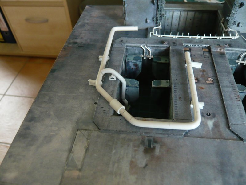
and can finally give rest. And so I will now also scratch the remaining three of these outlets even before then follow the outlets with the tapers.
6 Likes
Hello everybody,
meanwhile I have bent into shape the remaining three 18’’ outlets and have tried, to make them as congruent as possible. While this is relatively easy with the upper arch using the template,

but the lower bendings are more difficult because of the short distances, because one needs suitable balsa pieces and must clamp them multiply. And then one has to make absolutely sure that one must bend the last bending of the two inner outlets laterally reversed.

But that looks at least so far not bad. Now only missing the outflow openings, at which I’m still fiddling about. 

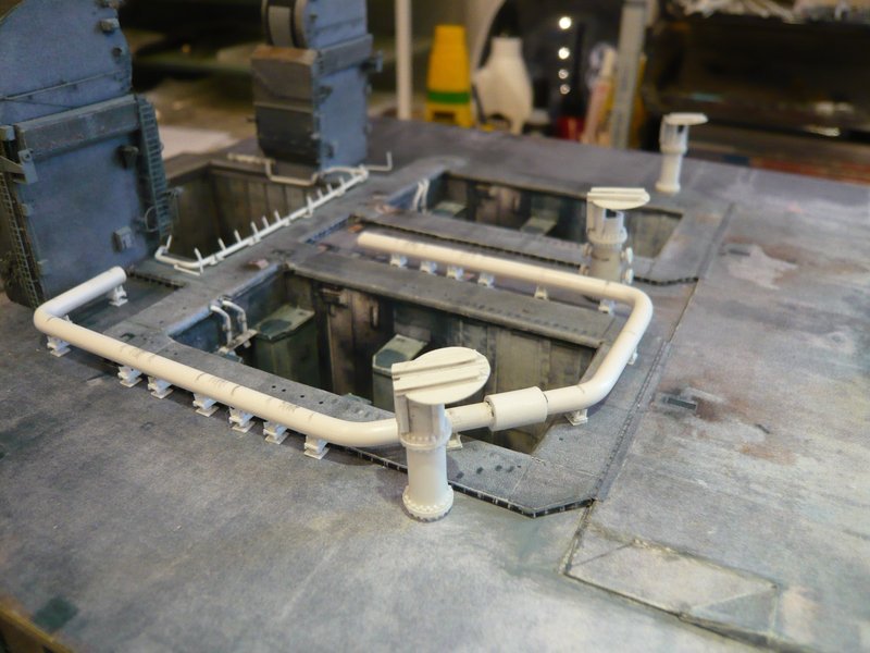
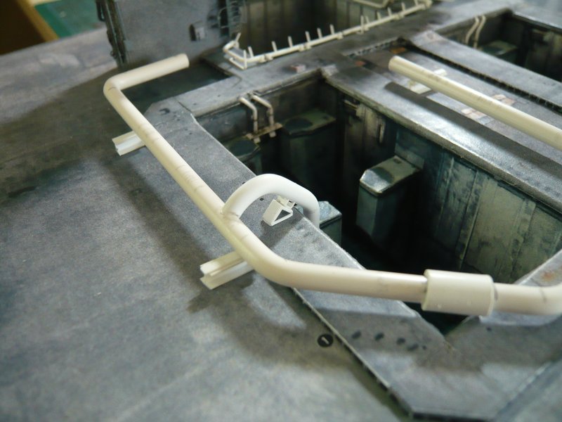
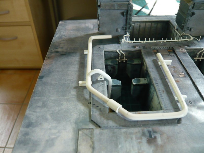
Then I have prepared two templates for accurate and especially stable positioning of the ring line above the SRB chamber because so far the test fitting of the disposals were pretty stressful, because the ring line is often slipped away from the support dummies. 


Now the ring line sits perfectly and relatively stable over the chamber, whereby the fitting of the outlets and later their installation becomes much easier.
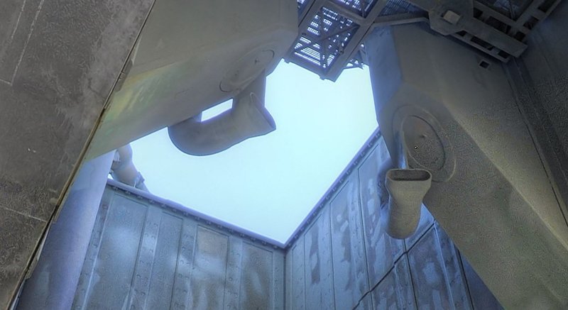
Well, and now the outlets between the SRB Supports come into play, which are rejuvenating downward after the top 18’’ arc to 12’’ (Ø 2 mm).

Source: nasatech.net
This I want to do, by bending the upper arcs according to the template and then the lower angled 2 mm outlet will be attached separately. And this transition is then modeled with Apoxie Sculpt.
I think at least that this technique should provide more uniform transitions than with the hot air draw technique. ![]()
And this I try then next time.
3 Likes
15 posts were split to a new topic: HTTP vs. HTTPS image links
Thanks Jim, ![]()
for the still missing nasatech links, I give in the new topic the page number and the image numbers for a final link via Robin’s mode with the heading 3D-rotatable view of this area at nasatech.
Then I continue to post and link in the same way or save myself the effort. After all, not everyone is as obsessed with detail as I am. ![]()
![]()
Hello everybody,
meanwhile I have bent into shape the remaining three 18’’ outlets and have tried, to make them as congruent as possible. While this is relatively easy with the upper arch using the template,

but the lower bendings are more difficult because of the short distances, because one needs suitable balsa pieces and must clamp them multiply. And then one has to make absolutely sure that one must bend the last bending of the two inner outlets laterally reversed.

But that looks at least so far not bad. Now only missing the outflow openings, at which I’m still fiddling about.

Then I have prepared two templates for accurate and especially stable positioning of the ring line above the SRB chamber because so far the test fitting of the disposals were pretty stressful, because the ring line is often slipped away from the support dummies.


Now the ring line sits perfectly and relatively stable over the chamber, whereby the fitting of the outlets and later their installation becomes much easier. ![]()
Well, and now the outlets between the SRB Supports come into play, which are rejuvenating downward after the top 18’’ arc to 12’’ (Ø 2 mm).
3D-rotatable view of this area at nasatech

Source: nasatech.net
This I want to do, by bending the upper arcs according to the template and then the lower angled 2 mm outlet will be attached separately. And this transition is then modeled with Apoxie Sculpt.
I think at least that this technique should provide more uniform transitions than with the hot air draw technique.
And this I try then next time. 
![]()
2 Likes