Pics are back! Awesome ![]()
Glad you can see them.
In order to ensure that I can butt glue the tapered portion of the lower shell to the previously-built straight portion. I needed to have an adapter that combined the straight and angled portion which could provide more gluing surface. Enter the 3D printer. I drew a curved adapter on SketchUp matching the included angle. It printed in 1 hour and 15 minutes and was just what was needed.
![]()
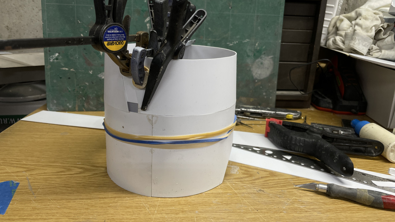
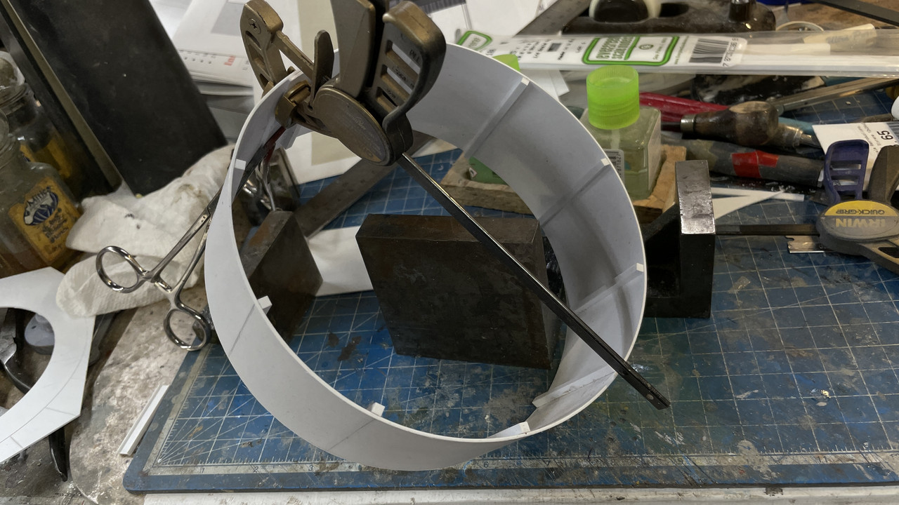
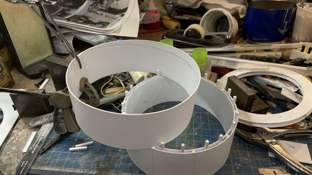
I cut out the tapered portion from the newly acquired styrene sheet using the glued-on-pattern method I used before. I glued the joint plate on one side, but did not glue the cone together. I waited to do this until the cone was almost entirely attached to the straight section, thereby taking up the slack as I went along and adjusting as I went.
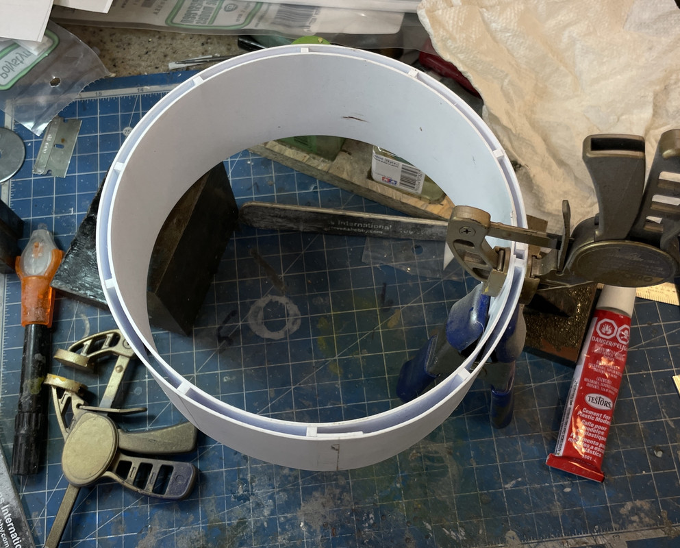
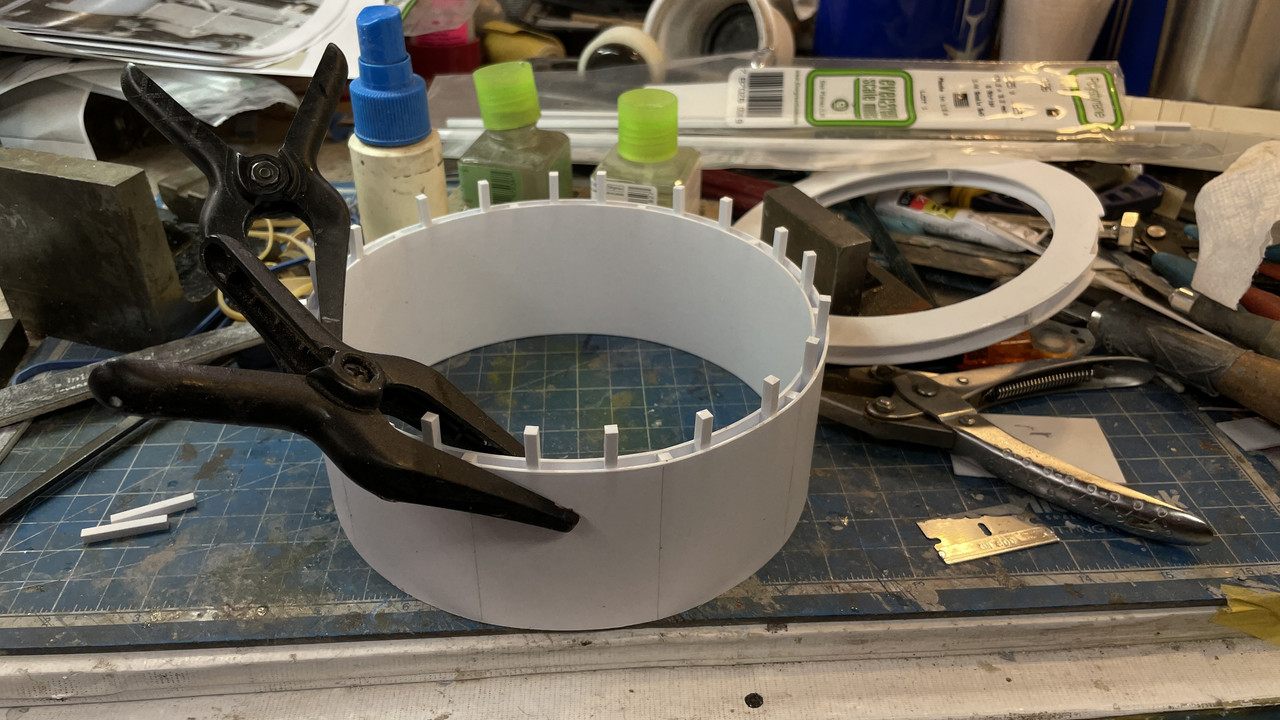
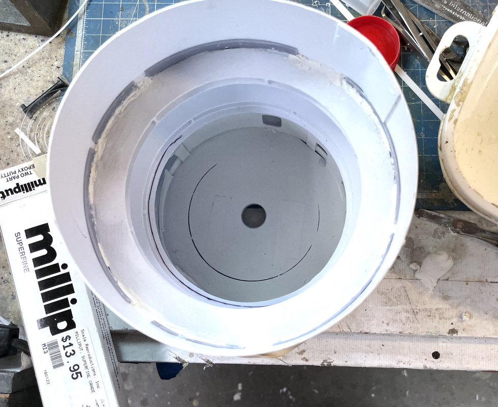
I used Gel CA to hold the adapters around the perimeter. The annular rings ARE NOT glued in, but later some thin CA did get down then causing a minor panic, since there’s a lot of stuff to do before I permanently glue them in. I got it loose quickly.
![]()
I could really use some longer clamps to get down the wall’s height a little better, but I made due.
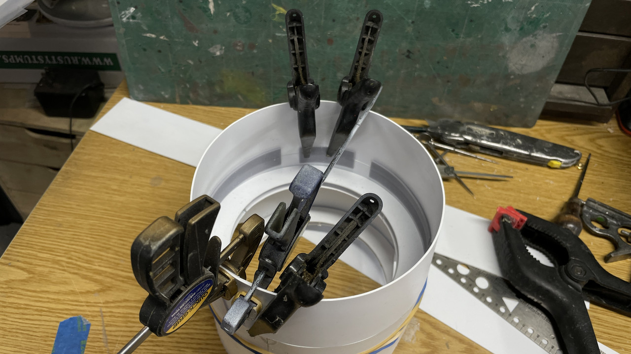
Gluing started out at the back center and worked around both ways towards the joint section. I glued the piece to the adapters using thin and med CA while trying to keep the long junction as close in contact as possible. I glued that line with solvent cement. There will be filling and filing to do, but that’s to be expected with pieces of this size and nature.
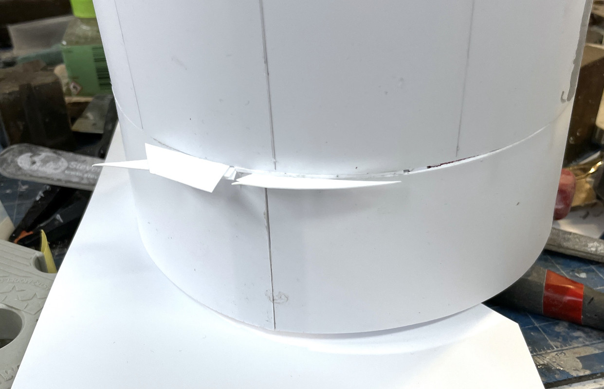
As with the other pattern-taken-from-SU-Unwrp and Flatten parts that I cut, there was a length discrepency here as well. In this case the flat part was short. To close this gap I’m filling it with some thing strips to better conform to a curve that would be difficult with such a narrow single piece. I can do wonders with filler and it will be fine. Besides, this is at the back of the model and will be covered by the upper barbette shell so it will be out of sight.

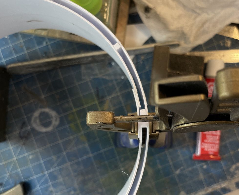
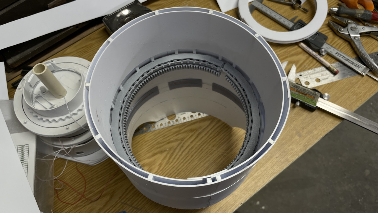
Just for fun, I decided to see how the roller track fit. This was a critical test and it passed with flying colors. The 3D printed part just dropped right where it was supposed to go. Amazing! The one dimension that I haven’t tested yet will be the pan deck sitting on the roller track and how much room will be below it. In other words, will the interior stack line up as it’s supposed to. I have absolutely no idea. It fit in the drawing… Hopefully it will fit or the shell would be too tall. I can fix too tall with some surgery. Too short would be a pain the butt…
Next session I’ll do the exterior filling and sanding.
I also cut both layers of the top barbette. Again, I’m not so sure about their lengths either, but I’ll figure it out. This thick barbette armored piece with be fabricated with an outer layer, 1/8" styrene spacers and then an inner sheet which, when all glued together and finished, will look like solid 14.75" inches of solid armor in 1:1 scale.
5 Likes
Brilliant progress, and so nice to see rubber bands working hard.Those, along with stone-age wooden clothes pegs are still my go-to tools….
Regarding the need for long callipers when clamps prove too short, I once used some small but strong magnets (from an old maglev train project I heloped my son with) to hold parts together beyond the reach of clamps – worked just fine ![]()
Fabulous build!
Amazing to watch process unfold!
Reminds of a few Mark Twaine’s quotes on education & school.
“I never let my schooling interfere with my education.”
“All schools, all colleges, have two great functions: to confer, and to conceal valuable knowledge.”
“God made the Idiot for practice, and then He made the School Board.”
Part of the beauty of being a miniaturist (sure sound more sexy than “model builder”) is the constant problem solving mode you have to be in, especially with a scratch-built monstrosity like this one. I often re-read the massive amount of words I’ve written in all the forums to which I contribute to accomplish several goals. First, it’s a blast to see how I’ve actually built some of this stuff since, like childbirth (so I’m told) you forget the pain and just look at the finished product with awe and wonder. And second, because I forget some of the tricks, techniques and work arounds I’ve used uto solve problems and may need to use again. I have one thread on O’Gauge Railroading’s forum where I describe the building of my railroad (still building) that’s been running continously for 10 years. I started it in 2012. I have some guys that have been following it since then.
Twain’s comments (as usual) are right on.
Only had a bit more than one hour in the shop, but made it productive. I got the upper armored barbette shell glued up. All that’s left is the slightly tapered (bottom o.d. slightly larger than top o.d.) shell and all the sheet stock parts will be constructed.
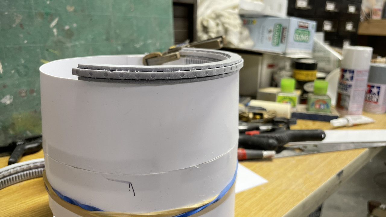
I used 1/8" square Evergreen bar stock to provide the spacers that will give the armored barbette its scale thickness. I spaced them every two inches and doubled up where the inner shell’s joint was going to fall.
![]()
I glued this to the round shape like the others with a splice plate and lots of strategic clamping. I never get it to adhere evenly across the entire face, and after some drying time, I went back and shot some thin CA into the gaps and changed the clamping scheme.
There was still some residual misalignment and gapping so I filled this with Bondic, power and hand sanded it all flush.
I then prepared the inner shell with it’s splice plate and got ready to join it to the outer shell. I was suspicious that the inner shell looked a little short so I made the splice plate a little oversized so there would be more room for the additional stock needed. It wasn’t much, less than a 1/4" Again, I started gluing the inner shell to the spacers at the point opposite to the final joint so the slack would build towards the joint.
Here is the final joint over the double spacer.
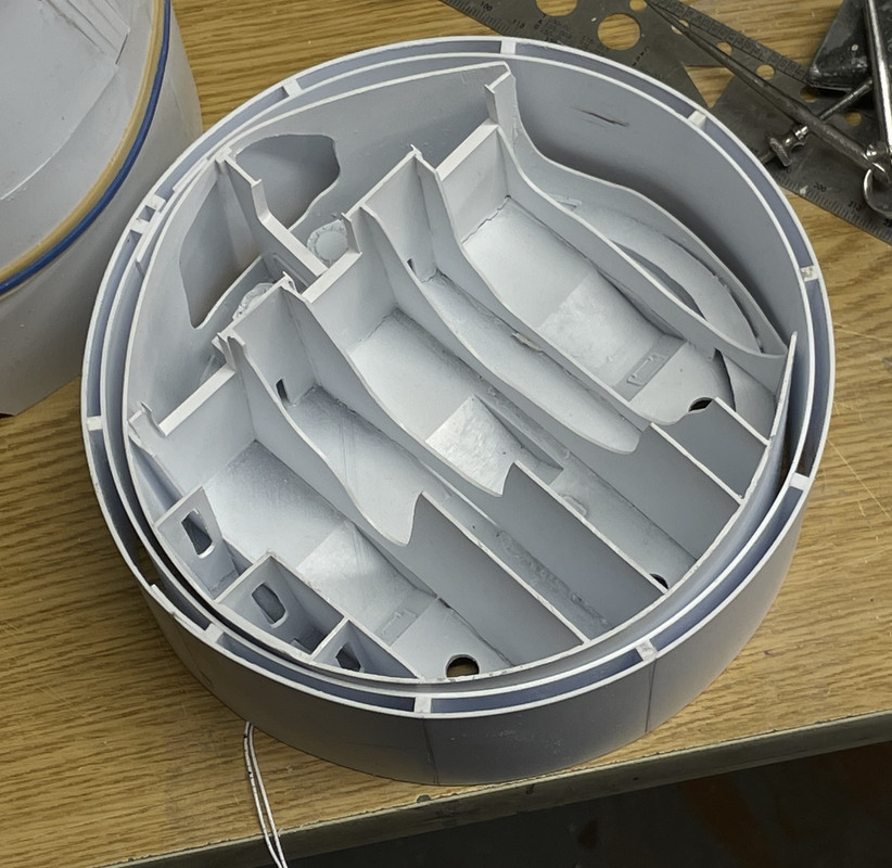
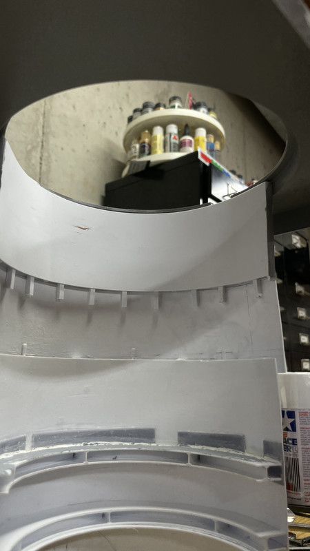
And here’s how the pan deck fits within the barbette upper drum. It fits closely like the prototype.
Tomorrow I will continue building the lower barbette skirt. The lower shell that I built yesterday joins the barbette structure at the lower edge of the lower barbette shell tieing it all together. It’s still chanllenging getting this big sheet stock stuff together, but I’m encouraged that it’s going better than expected.
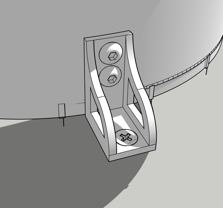
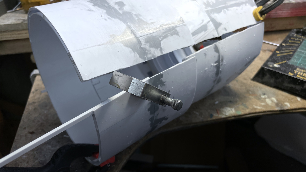
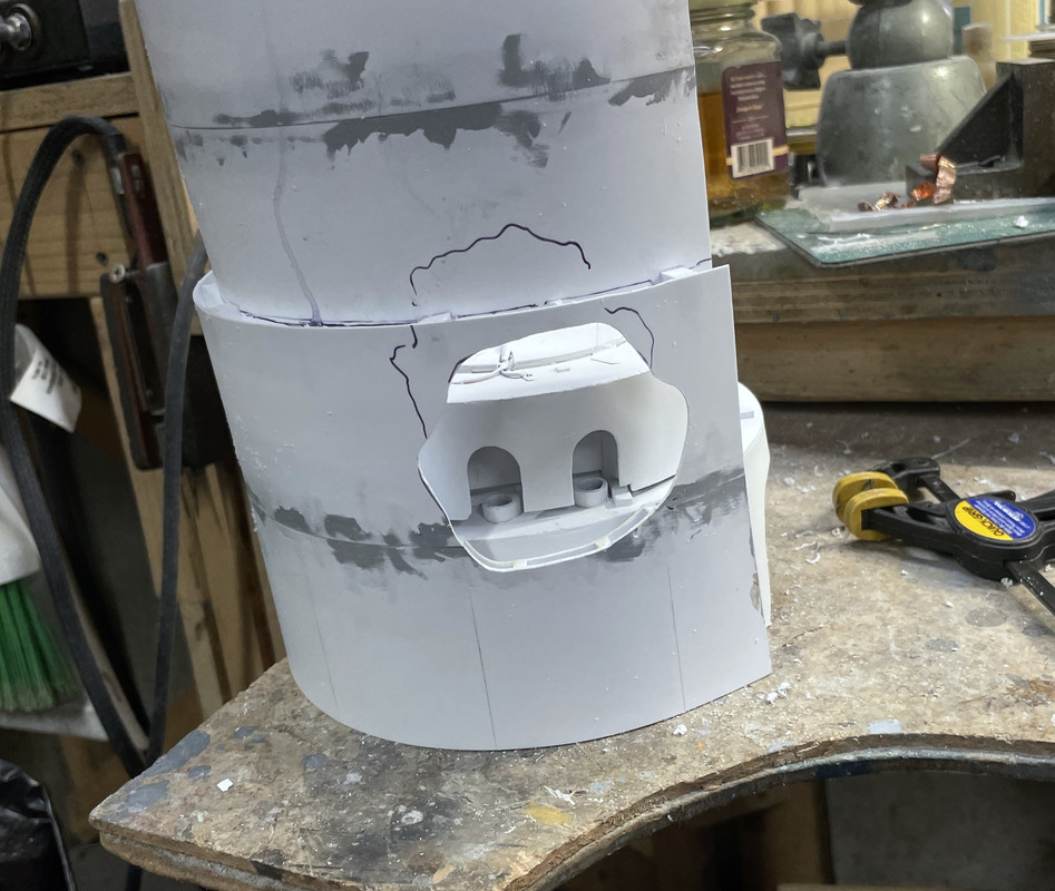
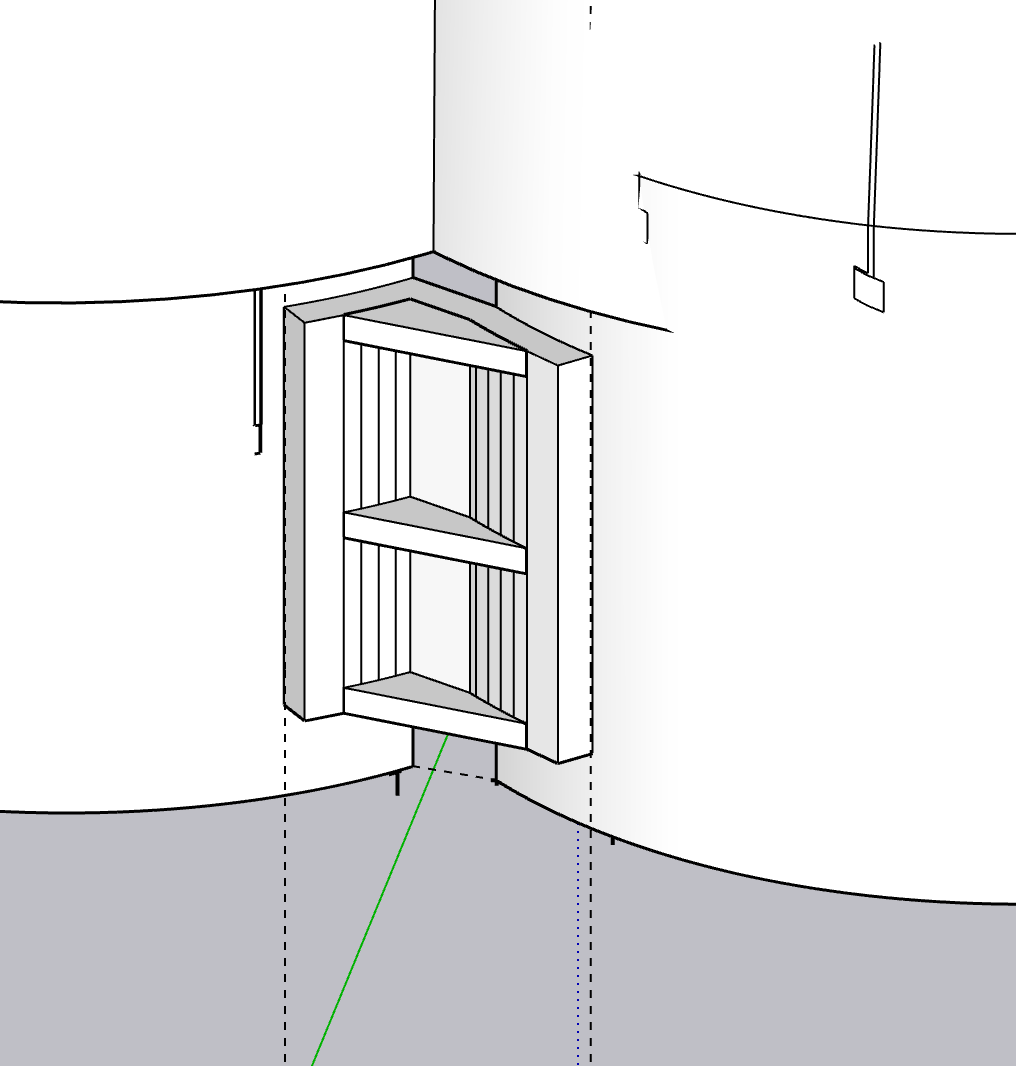
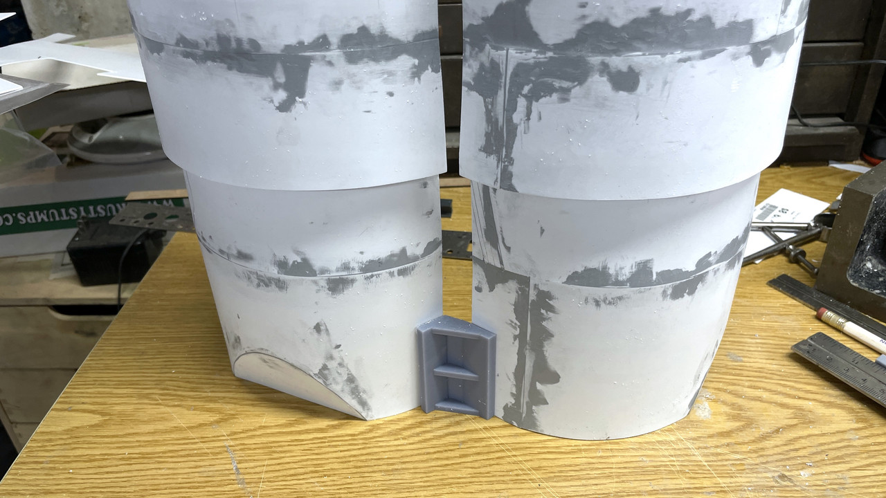
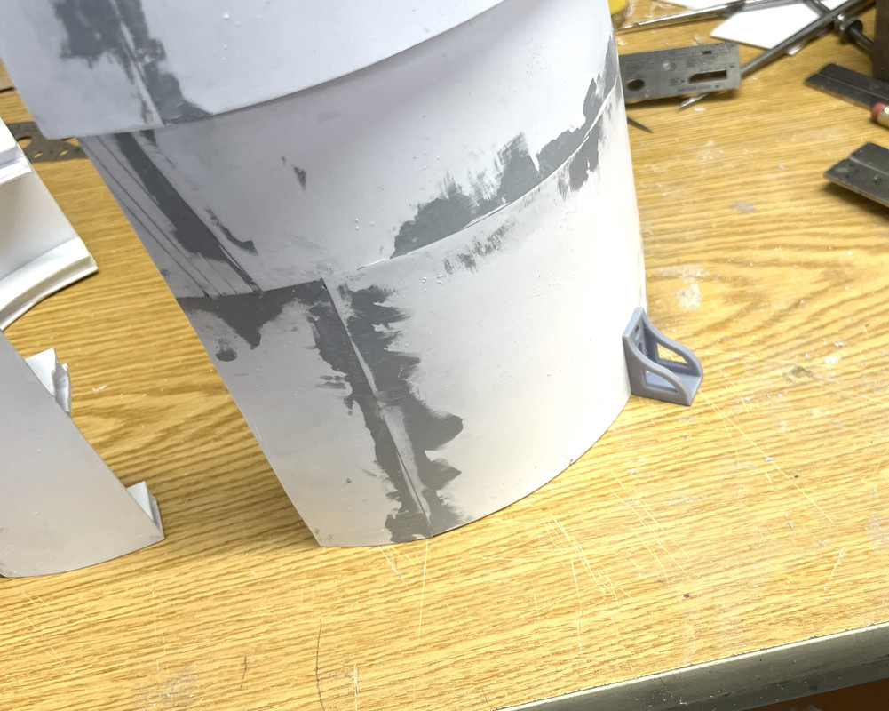
Believe it or not, there was still one more part to print. This is the stationary hydraulic bumper that’s affixed to the upper tapered shell on the lower assembly and provides a positive stock so the turret could not rotate in a position to either a) run afoul of the other turret and b) aim the guns at the ship itself.
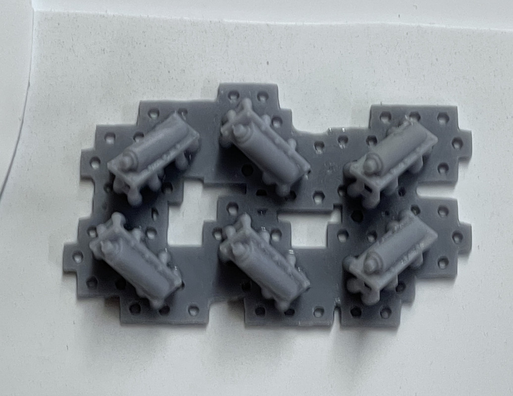
I originally was ignoring these two parts (R and L), since that part of the shell was not going to be visible to the viewer. But I awoke thinking about this this morning and decided to open the shell clamshells in two directions with only a small part permanently fixed to the back of the turret.
I will use the larger swing-away segment opening to the left that will expose the major cutaway sections, and then a smaller segment opening to expose the pinion gears and their relationship to the ring gear and roller track. I did 3D print a second hinge component and will put it to use. With that part of the shell being open, these two buffers would now be visible. Therefore, I had to print them. Took 20 minutes to draw it and 50 minutes to print them. There’s a right and left, but I only drew one hand and then mirrored the other one in the slicer itself which has this feature. As usual I print more than I need.
5 Likes
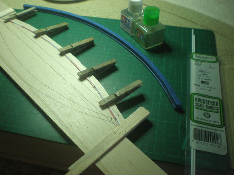
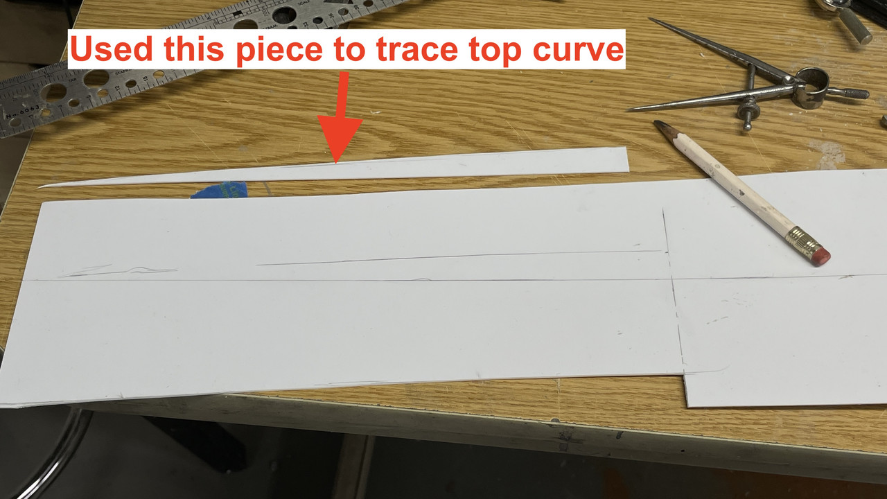
Work continued today on the barbette shells. I didn’t have a full-size pattern to trace cut the lower barbette skirt, so I did by taking the measurements from the non-scale drawing I printed. As with the other flat developed surfaces, I susepected this would need some tweaking and it did. To draw the long developed curves all I had was the mid-point height. I bent a steel ruler to form the curve and traced with a pencil. I only did one quarter of the curves (top and bottom) and then used the scrap piece to trace the same curve on the top. I cut the top and then used the same piece to trace the last curve on the bottom.
The piece was almost the correct length needing a little over 1/8" trimmed off the end to fit the upper barbette’s circumference.
In order to provide some substance I inserted 1/8" square stock into the upper barbette gaps and cemented them.
Glue up of the lower skirt went off without a hitch.
I glued the lower skirt to the upper armored section. There are some gaps, but I will take care of them probably with some slivers of styrene and then filler.
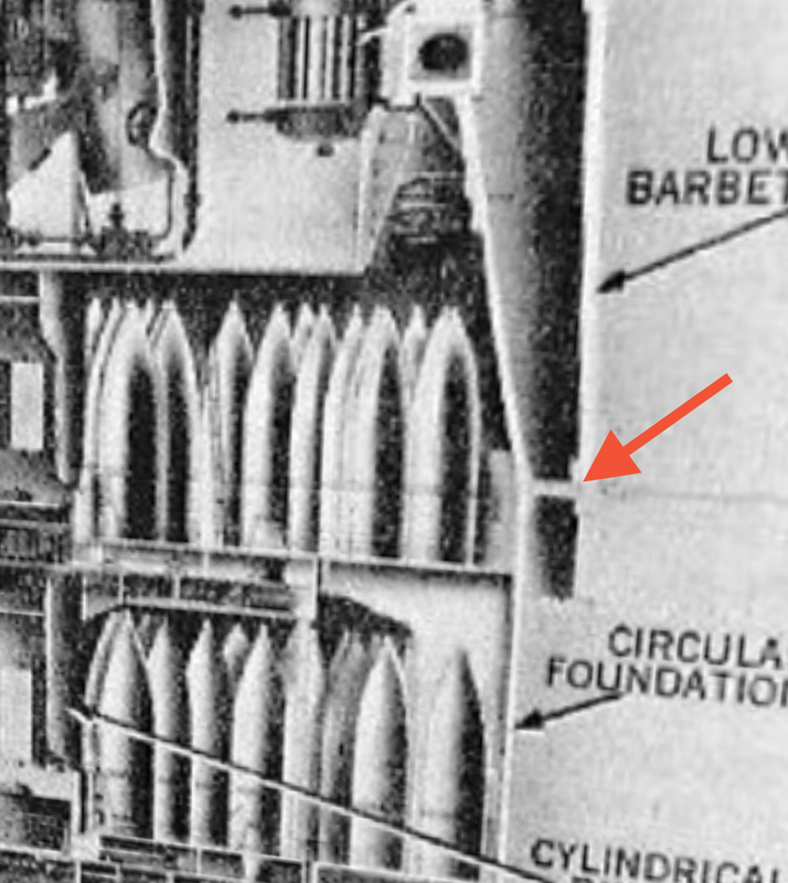
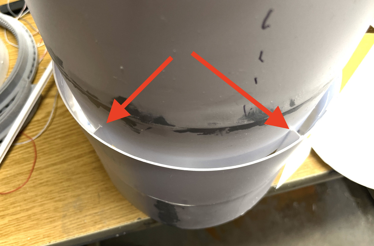
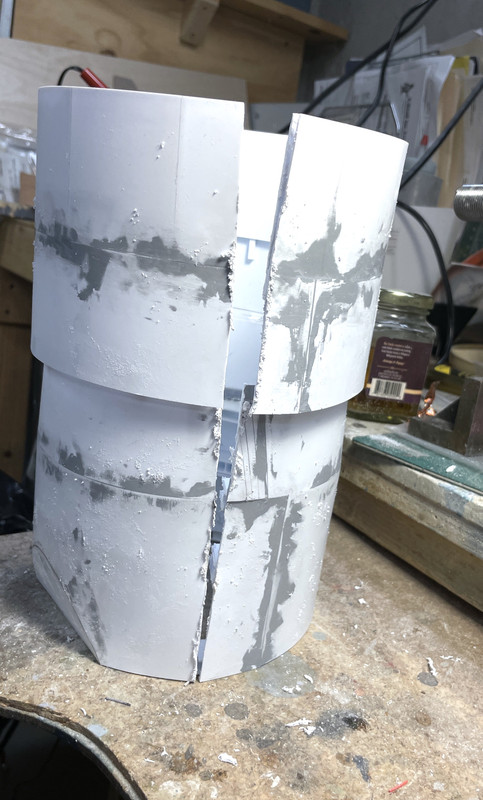
As you can see here in the best cross-section drawing I’ve found, the barbette joins the lower cylindrical bulkheads just at the crease at the junction of the tapered and straight sections. I needed to make a ring to fit this space. The shells are very flexible and not absoulutely round so capturing a perfect diameter was difficult. Notice that there’s some thick stuff on the other side of the taper/straight joint very similar to pieces that I 3D printed. Seems like life imitating art here.
The o.d. of the ring is somewhat undersized and the i.d. was somewhat too narrow. I was able to remove the excess stock from the inside diameter and get it to fit. I’m going to remake this ring with the new measurements. I’m out of big stock, so I’m going to make the ring out of multiple layers in segments with the joints staggered. I have lots of smaller pieces to do this. Having this ring correctly fitted is critcal to a good job.
![]()
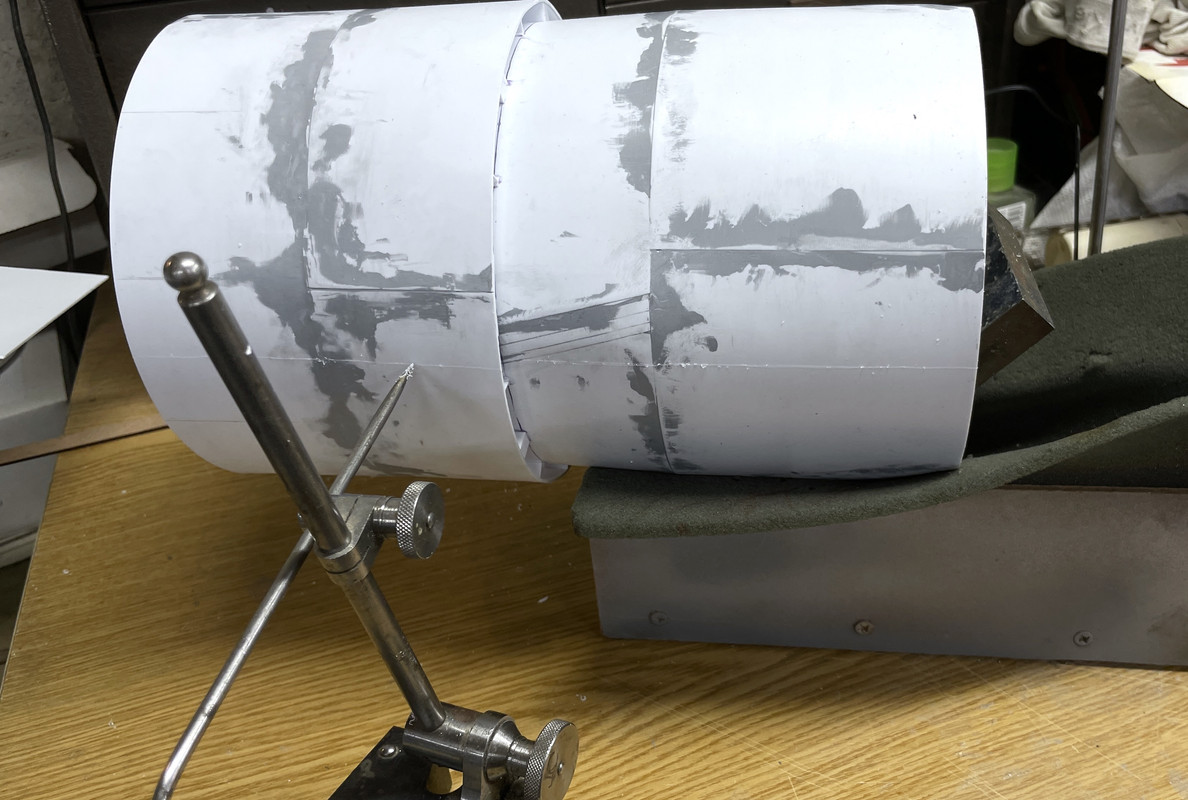
I tried dropping the barbette over the lower assembly and it sort of worked.
But… there’s a wrinkle. There’s always a wrinkle. The ring gear assembly has to fit within this space. It was another challenge to locate that critical part within the stack. And guess what? Those supports that I added earlier in the day were in the exact spot the ring gear is supposed to lie. I suspected adding something that thick would come back to bite me. It did.
In this picture, the ring is sitting too high.
That leaves me two choices. i can attempt to remove the supports wihout distroyings the structural integrity of the lower skirt’s joint, or I can notch the ring gear at each support and thereby get it to sit a the right height. Or maybe there’s a 3rd choice…perhaps I can split the difference. Remove some of the support and cut some shallower notches. That may work. More crafting. I will repeat myself. I suspected making these large tapered/cylindrical aspect of the build would be most ambiguous and I was correct. It will work out in the end.
7 Likes
Ouch – makes me wonder of they had a similar problem translating plans to reality with the 1:1 version. Zero expertise to offer, but logic suggests your 3rd option’s worth trying. If it doesn’t solve the fit problem you’re already half way there for option 1 or 2, and there’s no down-side.
The problem resolved itself. As you’ll read near the end, the correct positioning of the barbette cylinder doesn’t not go down far enough to intersect the ring gear’s position. I imagine the rear-world welding and forming all these interlocking bulkheads and tapered cylinders must have be very difficult indeed.
I started a short session by filling and sanding yesterday’s joinery. I am using some styrene strips to fill the big gaps and then use filler. Filler doesn’t like filling empty air. This will have all night to dry and I’ll trim and finish the filling tomorrow.
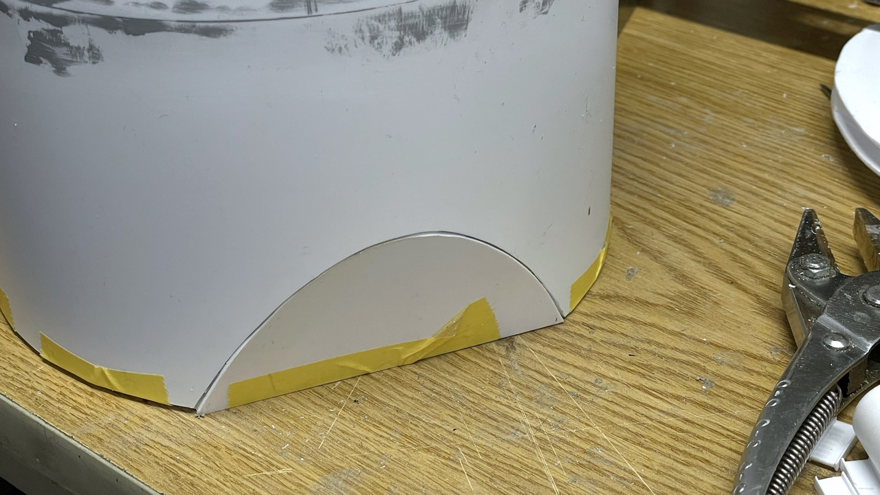
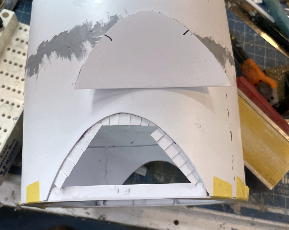
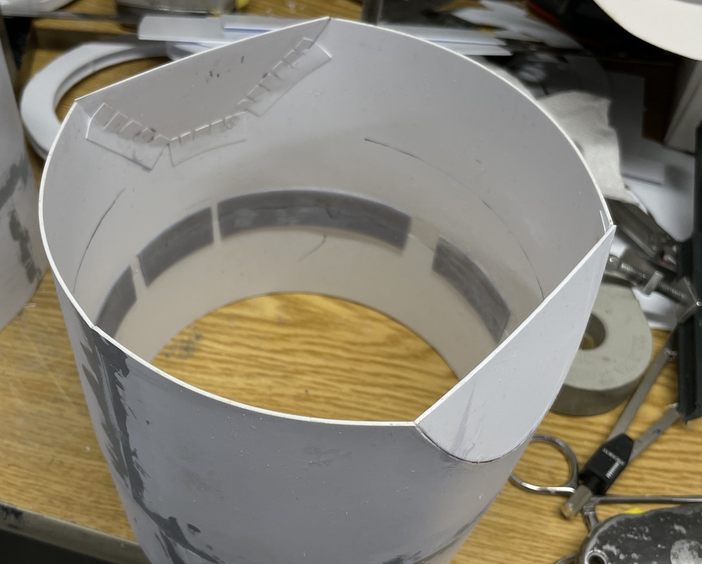
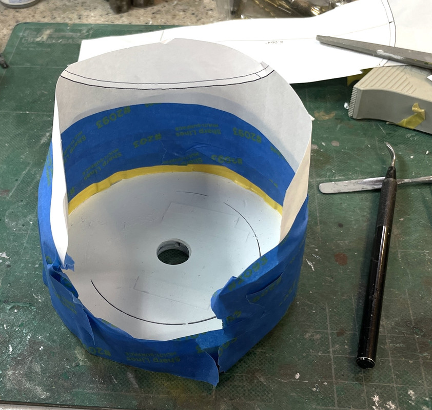
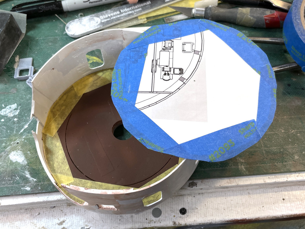
I also needed to get accurately cut truncate pieces. My first attempt at tracing the opening was way off becuase I was tracing the opening WITHOUT the bottom ring to stabilize the cylinder. As I pressed the cylinder down on the sheet stock to trace the opening it distorted and the cut piece didn’t fit. It re-did it, but this time with the ring installed and taped in place. I got two good tracings. I then did some final fitting and taped it in the opening to see how it worked.
I then had to figure a way to structural support this to glue it and came up with this. I was tempted to glue it, but held off because I have to be sure that I can get the annual rings into position, and these flat pieces close down the bottom opening. I’m at a point where the sequence of assembly is going to get real serious really fast. Some things better go in before some other things or it will not go togther.
I needed to adjust the size of the upper projectile flat ring since the i.d. of the space where it’s going is slightly narrower than the lower projective flats ring and it was also impacted by the those junction pieces holding on the tapered section. I needed to get an i.d. measurement of this space. I even resorted to making a measuring device that I could transfer those inner diameters to set the calipers for circle cutting. My dividers didn’t open wide enough (just a skosh over 6") necessitating the creation of a makeshift measurement transfer device… two pieces of Plastruct I-beam and an aluminum clamp. This worked, but the measurement I kept getting was the same as the ring I already had. I ended up marking the ring where the junction peices were. I notched the ring leaving the lands to actually contact the cylinders walls.

Then I tried like crazy to redo that spacing ring and still couldn’t get it the right size. Yesterday’s ring was a good 1/16" undersized. I cut a new ring, to laminate it to the existing one to give additional stiffness AND enable me to make it out of two pieces of styrene since I had no more pieces of sufficient size to cut a 6.25" circle. The pieces I cut ended up being undersized also… not as bad as the original ring, but still not right.
Then I had a flash of brilliance. The real ship uses structural steel to space and connect the barbette lower skit to the tapered inner shell. I wondered if some Evergreen I-beam would be the right size to fill this gap. I cut four pieces of the 1/4" I-beam and temporarily glued them to the perimeter at four points. And IT FIT!
At first, the fit was a little tight and distorting the inner cylinder, but then I realized that I was inserting the inner sleeve too far and getting to far into the tapered section. After carefully marking the actually overlap distance, the I-beams spacing was pretty darn good. I only need the I-beam pieces to be as long as the overlap. I went back and trimmed the ones I cut to this depth and then cut a bunch more using the Chopper with my depth stop mod. I then reglued 8 equidistant around the perimeter and tried the fit again.
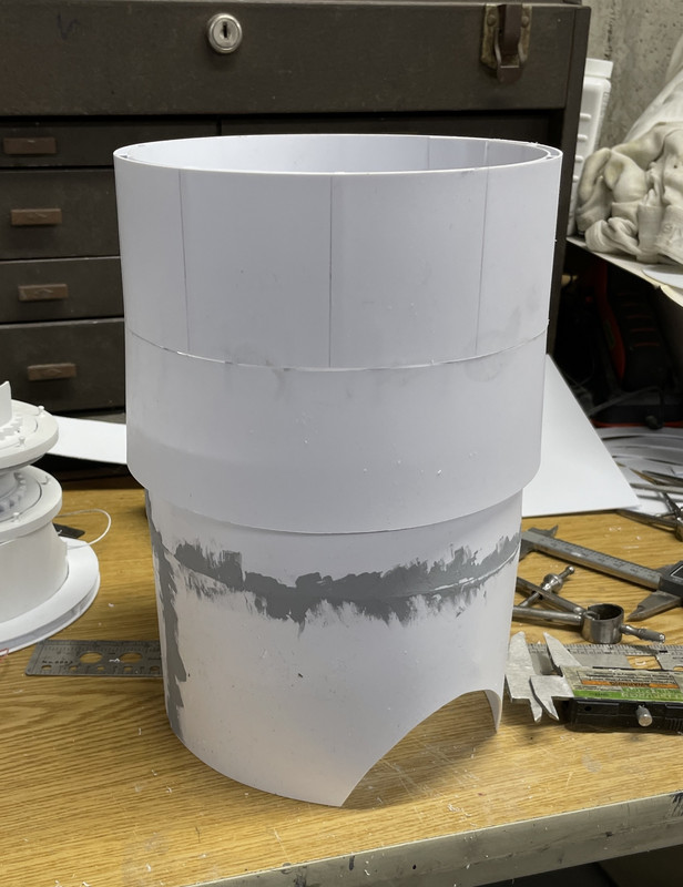
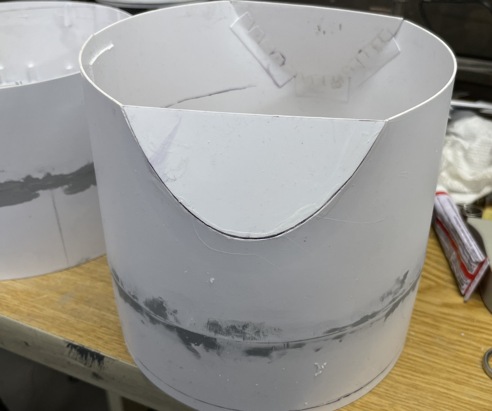
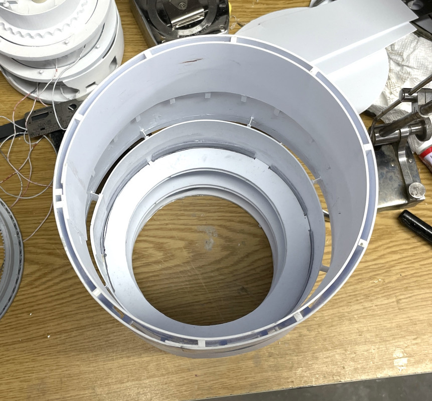
Here’s a vertical view of the intersection. Having the exact same sized spacers around the perimeter ensured that they are sitting in perfect concentricity. In this view you can see which is the foreward direction. The truncated cuts aren’t symmetrical…. they taper towards the bow since the ship at #1 turret is already starting to get pointy. It’s helpful to me as well since I can easily keep track of the orientation.
![]()
Again, I held off gluing all this together. I need to access the lower cyliinder a lot and will install the upper barbette later on. I also happily found out that the connection pieces I added yesterday DO NOT run afoul of the ring gear. They sit well above where the ring gear goes. It sits right on top of the lower tapered bulkhead’s top edge. And that’s a happy thing.
I also will set this up with a surface gauge to ensure that the top mounting surface is parallel wit the base before I glue it for good.
When all this is glued up as a solid I have to cut it apart for the clamshells. I also decided I’m just going to make a small cutaway to display the pinion gear area and leave the other clamshell as I originally was going to do it. I have to keep in mind where the 1/8" spaces and the I-beams are since I don’t want to have to slice through any of them. That would be bad.
5 Likes
I’m just about ready to prime all the outer bulkheads. After noodling it around a bit, I realized that I had to glue in the truncated faces now. There was too much fussing with it to have all the other ring decks in place. My styrene “fingers” worked pretty well, but I had to take care with the clamping. Thin styrene under action of solvent cement can decompose a bit and break rather than bend. I did break off a couple before I backed off on the clamping force.
On the front side of the joint I went around a filled it with Med. CA after pre-spraying with accelerator. My Med CA is aging a bit and needs a lot of help to get it to kick. I used my MicroMark power micro sander to knock off the high spots. I did mitigate the lumps by squeegeeing the CA with a straight razor blade before it set up.
After more sanding with various sanding sticks (wet with water), I filled it with Tamiya Filler and then sanded that when it set up
Meanwhile I was waiting for the massive filling job on the upper barbette cylinders to dry so I could get that contoured properly. Before the end of the day, all of that filler was sanded, refilled and sanded again.
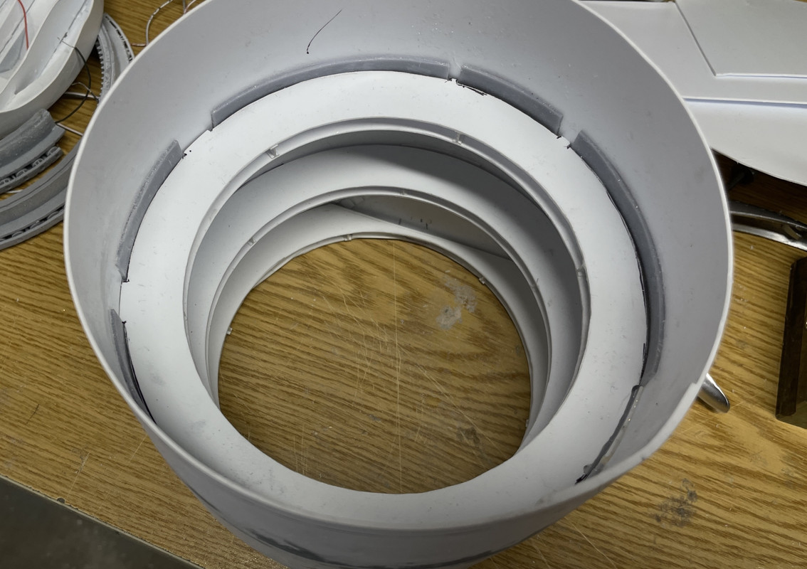
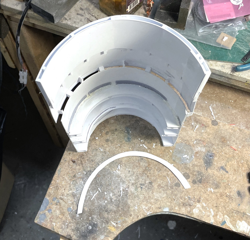
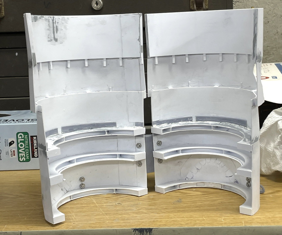
All the filling is now done. I test fit the rings to make sure I could assemble them with the truncated parts now glued in. I was able to put the lower ring in by angling it, and getting in the upper two circular annular decks from the top. They all fit nicely.
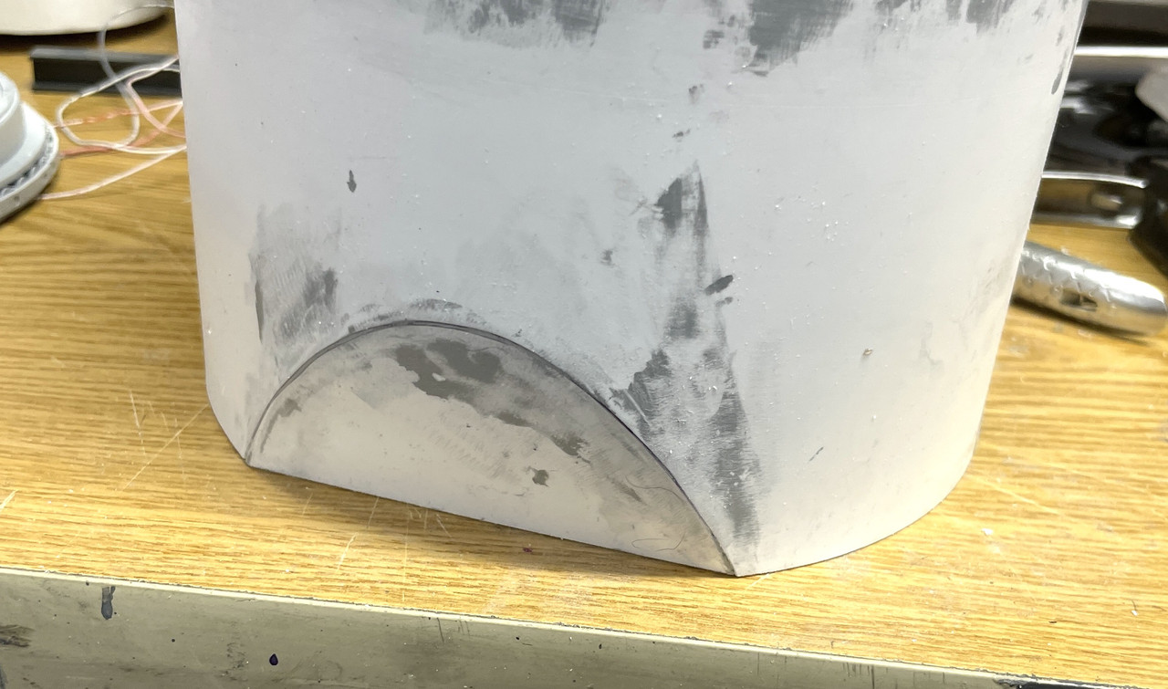
This view clearly shows how I notched that upper ring. I described this in words last post, but the picture is much more descriptive.
I also used a surface gauge to trace the top edge of the lower bulkhead assembly to ensure that it was parallel to the base. It wasn’t! I set the surface gauge scribe to the lowest point, and scribed a line revealing all the high stops. I cut off the excess plastic with a diamond-coated abrasive cutoff wheel and then a sanding drum on the Dremel Flexi-Shaft. I then sanded it flat on a piece of wet-or-dry emery paper glued to my granite surface plate. It reduced the overall height by about a 1/16" but that won’t matter in the scheme of things. I re-scribed the witness line for the barbette’s lower edge since the earlier line was based on the old top edge out-of-parallel line.
Here’s the entire bulkhead stack ready for glue up.
I was going to prime everything before gluing. I’m changing that. I’m going to glue the stack, then split it. Splitting it could make a mess so I’m not worry about paint. I will prime everything then… inside and out. Furthermore; it will be easier to paint and detail the annular decks. I’m depending on all those annular rings and the doubling of the upper barbette shell to keep the cylinders from opening up. It should be okay [:S]
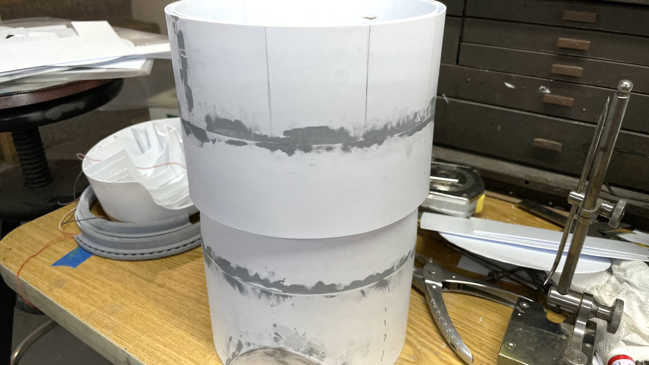
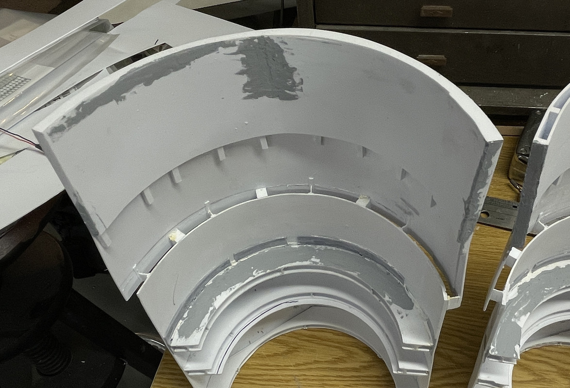
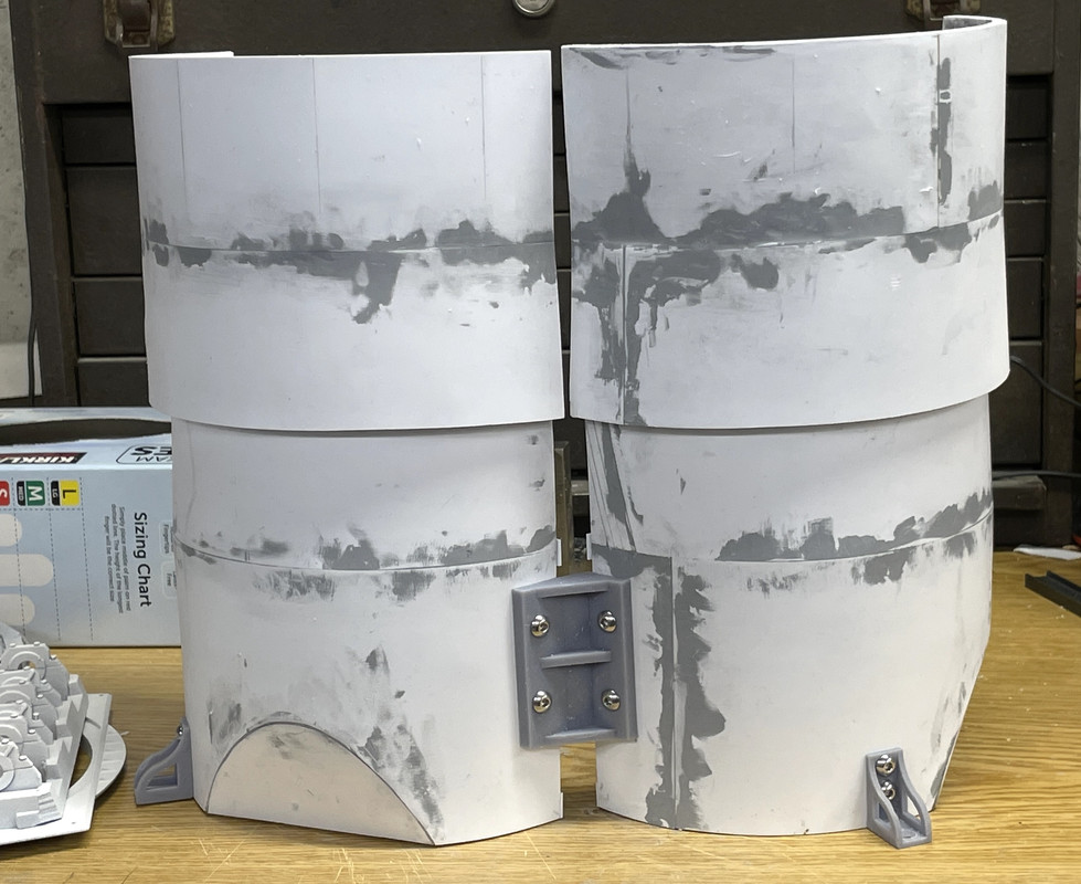
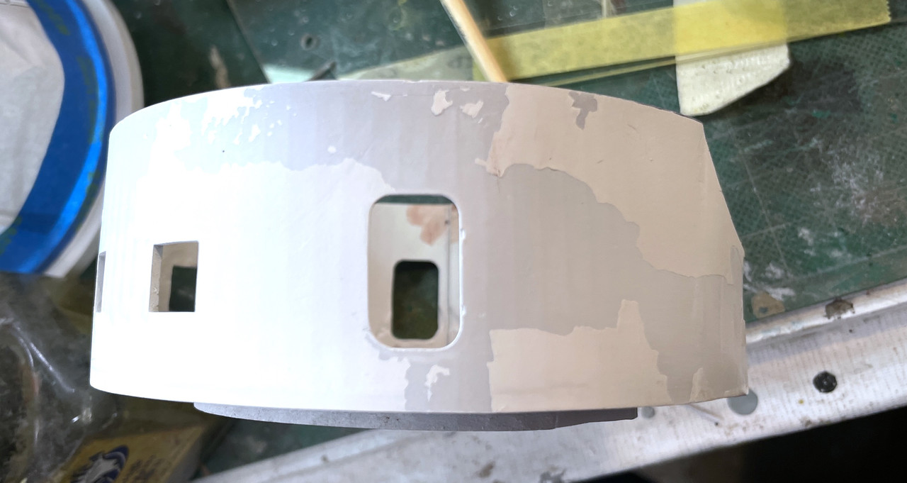
Here’s the stack from the outside showing all the filler necessary to make it look nice. This is the seam side and it will be facing rearward, so any imperfections (albeit minor) will not be viewable.
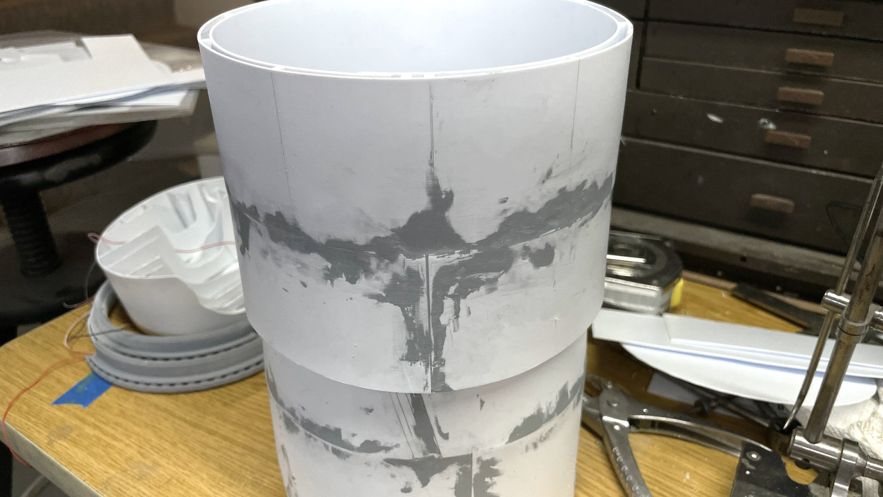
This is the viewing side.
As I said before, this was the most challenging and ambiguous aspect of the build for me. With it now complete and ready for final assembly, the rest of the construction should move along nicely. The change from this raw material to finish painted parts will be dramatic and I am looking forward to it.
7 Likes
Rare Sunday night report…
First of all, even though we live in Louisville, KY, we spent the first 64 years of our lives living in and around Philadelphia and the Phillies are now going to the World Series.
I’ve been troubled trying to figure out the best way to add a small detail on the model—the ladder rungs attached to the central column. I was going to use wire to make these, but the question was how to install them off the model and then get the column through the holes in each deck. I could install them off the model and cut relief notches in the decks so the rungs could pass through. While this could work, it seemed a bit dubious.
This morning the thought came to me to 3D print the rungs—correctly shaped I might add—with just a small substrate underneath to a) space them properly and b) facilitate their installation.
This is what I drew:
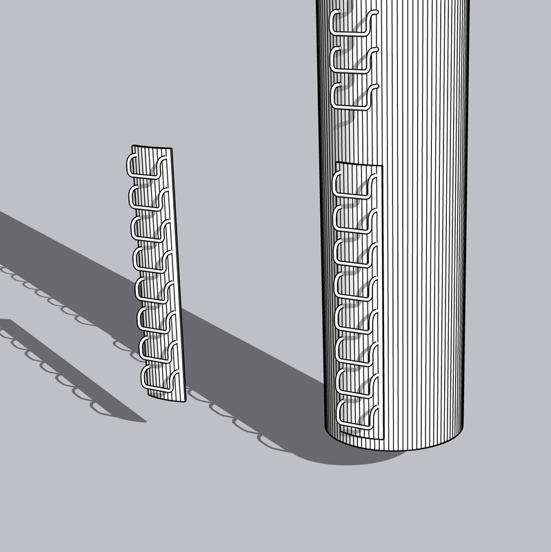
By building in the correct curvature for the 5/8" column, and keeping reasonably thin, the substrate would practicaly be invisible. I need three sets: Powder flat to Proj. Flat 2, Proj. Flat 2 to Proj. Flat 1 and Proj Flat 1 to the Electric Deck. I made five. The rungs are very fine and will surely break some.
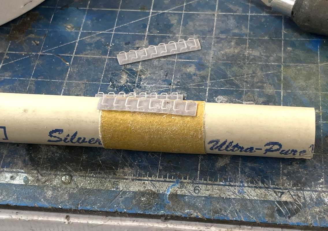
The print took less than hour and here’s the results.


I trimmed this one just a bit and then post-cured it to see how tough it is, and it will do just fine. I can now install the ladder rungs along with installing all the other apparatus on each deck before placing the next one of top. You can just see the slight curvature of the substrate so it will nestle into the column’s curvature.
Boy! Having that 3D printer does magical things!
Tomorrow will be a full work session. Hopefully I’ll do some more outdoors painting since the weather will be perfect.
8 Likes
The ladder rung sets are cleaned up. I used a different end nipper with very sharp edges to carefully remove the supports attached to the rungs themselves and was rewarded with very little breakage. I got three perfect pieces out of the five. I used the Dremel with Flexi-shaft with a spherical diamond burr to clean off the majority of the support nubs on the back. I then attached a piece of self-adhesive fine grit sandpaper to the same piece of tubing that’s going to be the central column and finished sanded the back.
With the back contoured correctly, the fit is really good. I won’t be installing these until the decks are in place. I will install them before the deck above gets put in place giving me good accees to the column. The Xacto knife gives a good indication of scale.
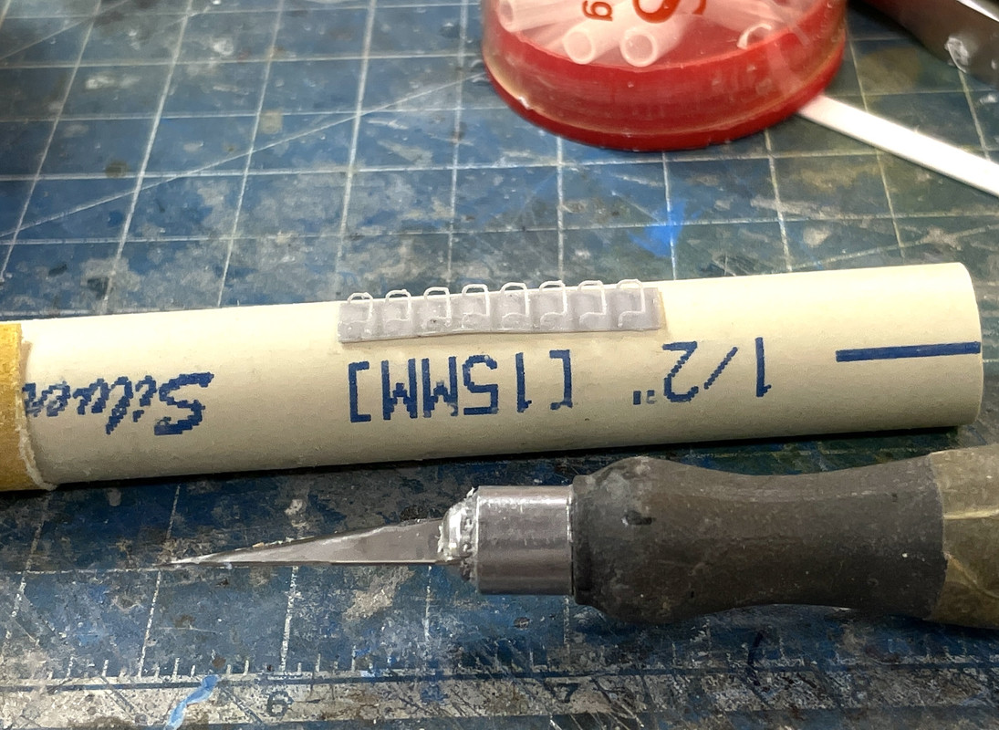
I put these away in a plastic cup with a lid so nothing will happen to them until I’m ready.
I had sort of a milestone day. The three ring decks are now glued in place. I also used epoxy putty to fill any remaining gaps to the shell walls and waiting for that to cure.
Before installing the number 2 ring, I needed to do a slight modification to the ring. The powder flat walls, being 3D printed, were not perfectly circular and the projectile flat didn’t sit nicely on it. It would rest on one side, but fall in on the other. I made a single-layer, slightly smalled i.d. ring, and glued this to the projectile flat one’s ring bottom, thereby making a nice seat for the proj flat to rest on.
There were some gaps in the ring’s fit due to some slight out-of-roundness of the shell. I made some 0.040" shims that I glued to the ring before installing. I tapered the ends of the shim so it would transition smoothly to the areas that fit tightly.
With that change, I was able to assemble, not glue, the #1 projectile flat ring which now rested squarey on the powder flat, and tested this by dropping the projectile flat onto this. When it was aligned nicely, I first used solvent cement, and then filled bigger gaps using Testor’s tube cement. I let this cure a bit and then got ready to do proj. flat’s #2 ring.
My concept of notching the ring to fit into the spaces between the 3D printed transition pieces didn’t work. Reason? When the lower ring was actually glued in and tight, the cylinder no longer flexed enough to get this ring in with those nubs sticking out. They had to go. No loss… I also shaved some stock off the lower ring in the assembly so it would slip over that sharp edge of the 3D printed transition pieces. With that change the ring got into position. I double checked by height marks on the cylinder’s i.d. since the stack was now 0.040" higher due to that extra spacer ring I added to proj ring #1. I then set a small combination square to that depth. I started gluing at one quadrant with the ring pressed up against the square, then went across the diameter, and again pressed it against the square and glued it. I finished up with the other two quadrants using the square.
This ring needed to be glued in with CA since the UV resin is unaffected by solvent cement. I used only med. CA. I went around once, added more accelerator, and then filled more gaps. There were still more gaps. In this case I used Milliput epoxy putty. The material was still not fully cured at the end of the session. I will do some final finishing on this tomorrow.
I could now go back and remove the powder flat and finally glue the bottom ring into place. Again, I used a combination of solvent cement, tube cement and med CA. With the lower edges of the truncated flat finally glued to the bottom. I went around and did final sanding and filling of the lower cylindrical structure.
I measured the spacing for parallelism between proj deck 1 and 2 and was rewarded by the tolerance of a max of .004" around the circumference. This accuacy will be appreciated when installing the deckf supports.
Everthing will be cured tomorrow and I will do any final finishing. I will then glue the barbette portion in place. When that’s dry, the GREAT SPLITTING will take place and we’ll see how it all hangs togther. After splitting I’ll install any angle supports and deck girders (already printed) and then do the priming and painting of this major structure.
7 Likes
Amazing updates and it’s looking terrific with how it’s all going together.
Things like this, and more so the real thing are mind boggling with how the engineering all ties in and it all ticks over to get a gun firing. ![]()
1 Like
I am really impressed with all your construction work. Most of the time I understand hardly anything you write, but that is moslty due to the lack of knowlede on my side. Yet your pictures speak volumes.
2 Likes
I am in awe of the naval architects who can fit all this stuff into a steel shell and make it float and do it for 80 years… that’s how old the New Jersey is.
I hope you can understand more of what I’m doing. I try to take some of the mystery out of it. Many of the things you read in the modeling press don’t get into the trials and tribulations we builders go through.
Short workday… PT, but did some good stuff. I added some more spacers around the perimeter of the Barbette/Lower Bulkhead junction. The interface between the two is just a bit over a 1/4" long and it’s critical. I didn’t have any more of the 1/4" I-beam so I substituted some 1/4" square stock. It’s not visible, so it doesn’t matter. It’s not very secure. The only place I didn’t insert it was at the splice plate where the gap was significantly narrower. The picture is looking bottom up which is why they’re out of sight.
![]()
While this was setting I actually started some finish painting, putting on a coat of Tamiya Flat White with the airbrush on everything that was going to be white. I did NOT do this on the insides of the rear gun compartments or the back bulkhead. The Tamiya Flat White Primer is pretty white and I wanted this coat to no be dissolvable by Tamiya alcohol based paints. If I overpainted them with the flat white, I would need to seal the surface with Dullcoat so the colors wouldn’t bleed.
I didn’t take any pictures of this painting since you can’t really see any difference with the primer coat.
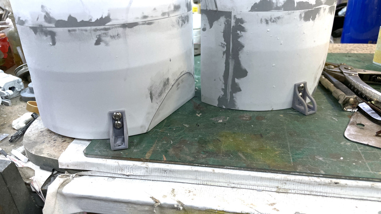
I needed to have a secure way to tie all this flimsy styrene sheet stock to the wooden display base so I drew something that would do the trick. Two of these brackets will tie the shells to the base. They’ll be in back and not easily seen. The center pieces will be held by the center column. I have a nice supply of M4 button head screws that will be held with nuts on the inside (or outside… whichever works best).
They just finished printing. I will be splitting the shells tomorrow and will be adding these brackets before painting.
7 Likes
My Impressed meter’s beyond repair, now looking for one rated for atmospheric re-entry. A thought about a wooden base, would it be worth covering in a thin metal sheet of steel-painted brass or equivalent? I suppose an argument against that being it could look bare without bulkheads & rivets…maybe you could build the rest of the ship around it. ![]()
3 Likes
Thanks for the terrific response! The deck is teak and as you’ll see further down, I have some challenges regarding the deck.
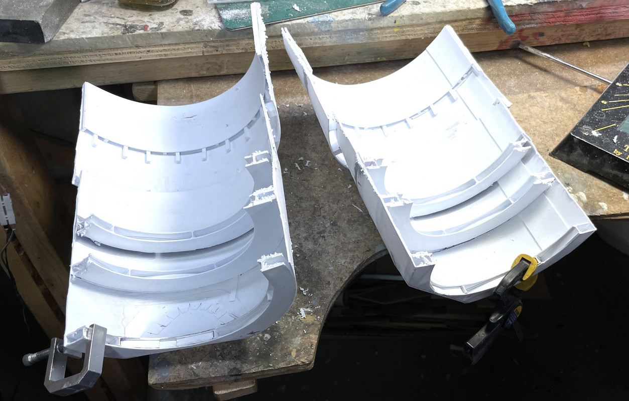
There was some serious modeling going on today. It was like cutting the Hope Diamond. One wrong cleave and all you have is worthless diamond dust. Well… maybe not quite that hyperbolic, but there was a significant probability that I could wreck over two week’s work and about $25 worth of styrene, and I didn’t have more stock to make another one.
Today was a BFD! A milestone day to be sure. I did get the shells split without wrecking them. I found that my hinge idea needed some revision, and I found that I can’t use the large kit decking piece.
Let’s start with the disection…
I scribed a horizontal line down the center of each side of the bulkhead assembly using my Starratt surface gauge. i supported the straight portion in a jig I made to support my O’gauge locomotices when repairing them. After scribing the line down the center on one side, I rotated the jig, without moving the bulkhead and scribed the opposite side. I was rewarded with two lines on opposite sides. I then highlighted the lines with a fine Sharpie using a straight edge.
How to separate them. I thought of using a razor saw and quickly dispelled that idea. I had to cut not just the skin, but the inner skins on the doubled portions and all the way through the annual decks. I ended up using a rather large abrasive cutoff wheel intended for cutting steel. When you abrasively try to cut styrene you essentially melt your way through it, but through it I got. The cut was ragged and not particularly straight, but it was within the margin of error and was fixable.
Where the cut occurred where there was no blocking piece right there, the styrene was spreading out. Before cutting the second side, I added new 1/8" stock to bring it right to the cut edge thereby stabiling the edge from further delamination and getting a head start on closing off the edges to simulate the solid armor plating.
I then cut side two and was presented with two shells that DID NOT COMPLETELY DECOMPOSE. There was some spreading at the exposed corners of the annular decks.
That aluminum clamp was used (among others) to re-secure these edges so I could glue them. I needed solvent cement; tube cement; and thin, med, thick and gel CA to finally get these springy bits to stay put. I do have fears about them holding up in the muesum envvironment and may need to do something else to ensure they stay attached.
On the open shell, the top will be visible and needed to be closed off to simulate the solid armor. I traced the shape onto some styrene and cut it out using the scribe and snap method (as will all the other pieces).
The above picture also shows that the open ends are all filled with stock and sanded flush, but not filled yet. I glued the top strip with solvent cement and held in place with some strips of Tamiya narrow masking tape. This image also shows several other features. I removed the parts of the of the inner-cylinder spacers that were peeking out over the edges of the lower tapered bulkhead to ensure that the ring gear/roller track will nestle in properly. There is also copious amounts of Tamiya filler that will be sanded before painting in the next session.
Both shells were now fully filled and rough sanded. Whew!
It was also time to open the last cutaway that would expose the pinion gear area. I assembled the structure with the pan deck and electric deck, rotated the shell to the proper orientation and drew the place the opening would go. I used the Dremel with a carbide router to rough out the hole. It too had to penetrate multiple layers, which I then cleaned with a sanding from on the same Dremel. In this image everything is upside down. Because the armor plate doubling will be on the top of the opening, I don’t think it will be visible, but I may fill the gaps with Milliput to make it look solid too.
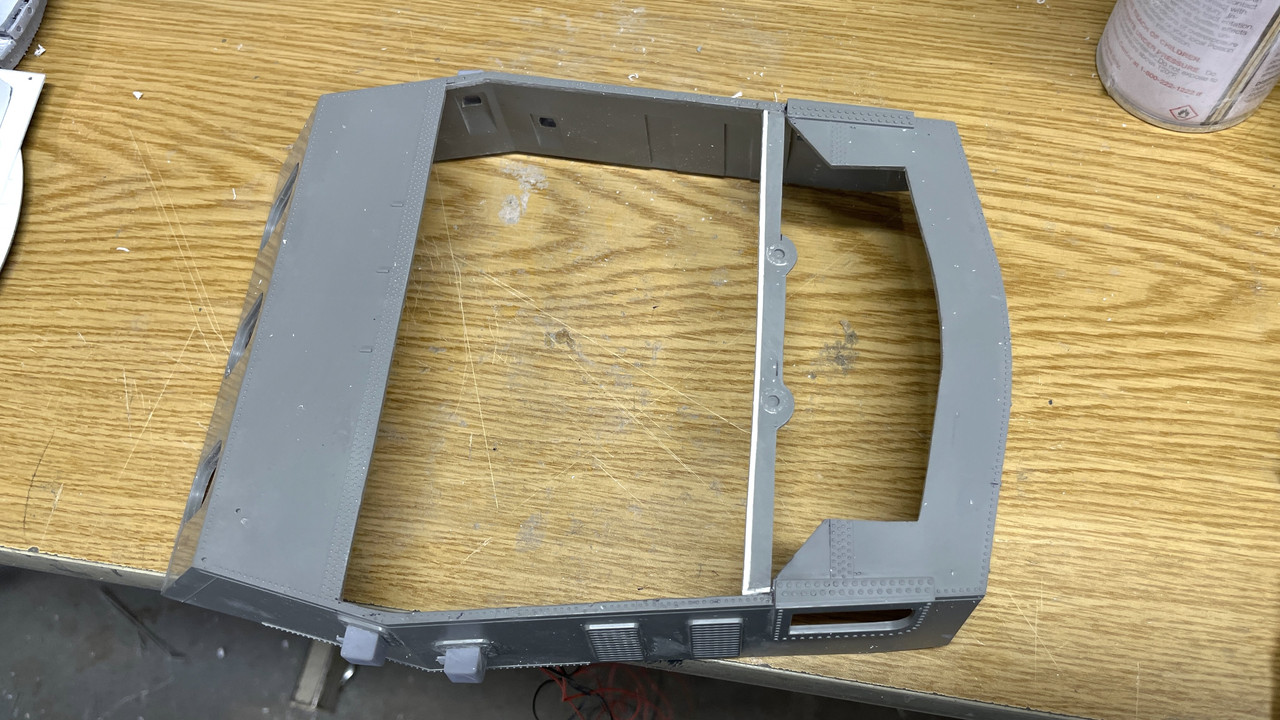
I was finally at a point where I could actually figure out how this was going to go together. I found out that I COULD NOT USE the kit’s large deck molding. I was planning on using it, but again, like the rangefinder ears that I didn’t draw and therefore didn’t include with the width measurements, I didn’t draw this part either. And it doesn’t work at all. Here’s why.
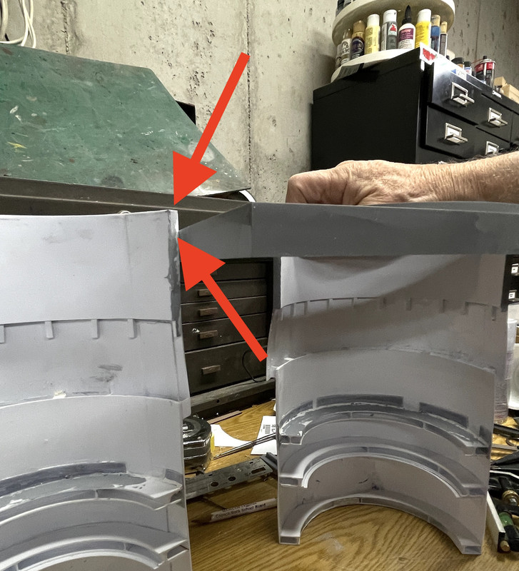
That difference in apparent height, is because the fixed shell slips up inside the raised gun house mounting, but the deck walls and deck and about 1/4" lower. To connect the open shell with the fixed one, I either have to mount the fixed shell lower or cut off the excess on the open one. And both choices create a mess since the bulkhead height is determined by the collective height of the internal decks. This view shows how the deck piece overlaps the shell from below. It looks great snuggled there, but screws everything up.
So I’m not using it. I’m going to mount the lower gun house plate directly on the fixed shell and the open shell now aligns perfectly. I may make a flat deck simulation piece. I found out from Ryan Syzmanski today that the teak decking planks are 5" wide. I might want to plank a piece with real wood stained teak… just think’n.
Here are the shells with just the gun house bottom. And it works!

The last thing was to see if my hinge idea worked. It really didn’t. It’s not wide enough to provide a good mounting surface.
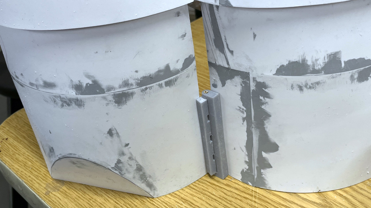
Furhtermore, since these shells are not moving, a hinge is overkill. I’m going to permanently screw the shells down to the baseplate. BTW: the brackets came out well and I will also be mounting them before painting. I’m just going to draw and 3D print an angle bracket that will hold the shells in the correct relationship, and that will be that.
With the shells on their way to completion, all the painting will commence in full. I got a green light to use the spray booth at my wonderful local hobby shop so I can spray the solvent-based paint when the weather isn’t cooperating. I’ve started playing with getting the right shades of gray to paint the apparatus and guns. This is the gun in the un-restored #3 turret and it looks kinda like haze gray to me. I may be able to use it for the guns. For the equipment, I’m going with a darker shade. This is pano that I took. You can see that the door frame is a darker shade than the gun’s yoke. I also have to add those ladder rungs you see in the lower left. The gun captain uses them to get up the alcove and out of the way of the maddening 4 foot gun recoil.

So… like I said. it was a heckuva day. I am very relieved to have the bulkheads done. The rest of the job, while painstaking, will be fun.
5 Likes
As predicted, short session today, but did get some stuff done.
This morning I drew in about 5 minutes a new junction piece to tie the two shells together.
Here’s the printed junction block. I have some clear space on the other side of the bulkheads to put the mounting screws. It’s way stronger than it has to be.
Because I drew this part directly in conjunction with the bulkhead drawings, I was able to build in the curvature on the back (both legs). You place the part INTO the other shape and “Intersect Faces”. What your left with is a line or lines of exactly where the two surfaces intersect and you can then shape the part to that line. The curves matched perfectly. While it’s not essential in this instance since I’m relying on screws and nuts to hold it, having perfectly matched surfaces is great if you’re going to glue them together. With the screws, having the surfaces matched will not introduce any stresses to straighen out the curves.
Also, here’s the finished mounting bracket(s). There are two of them. Between the massive junction pieces and the mounting brackets, plus the secure mounting of the central column, the model should be pretty secure.
I spent some time sanding and finishing the filler that I applied yesterday. I got one shell done. I will finish the other one tomorrow and maybe, just maybe might be abe to get the primer put on tomorrow. The weather is looking pretty good being in the mid-60s and sunny.
I also took time to clean off the workspace in preparation for painting everything. It was an unholy mess. They say, “a clean desk is the sign of a sick mind.” So what’s the opposite when it comes to work benches?
4 Likes
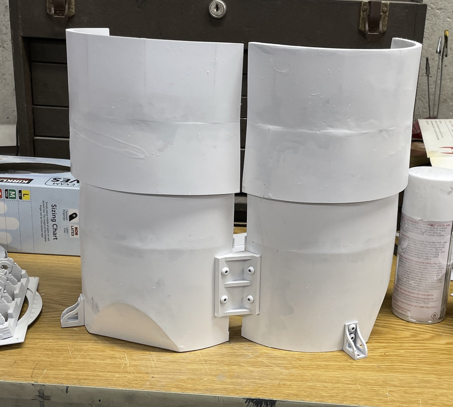
Weather cooperated this afternoon with temp at 68° F and a little breeze, so after doing some more work on the shells, I DID get to prime them.
I located and attached the base mounting brackets. Having the shells sitting flat on their bottoms, I marked the upper hole location with a Sharpie and drilled a small 1/32" pilot hole. I opened the hole with a 4mm drill. I’m using 4 X 8mm hex-button-head screws and nuts. I fastened the top screw and then drilled the bottom through the bracket’s hole. I was able to accurately located the lower hole by shining my work light through the translucent styrene so I could visualize where the annular decks were.
I fastened them in place in prep for painting.
I then positioned the center junction piece and again marked one hole on one leg. Did the same drill routine and mounted the one side with one screw and then drilled the second hole. I fastened the one side, brought the other shell into position, marked its first hole and then repeated the drill.
I mounted the bracket permanently and painted the shells with the hardware in place.
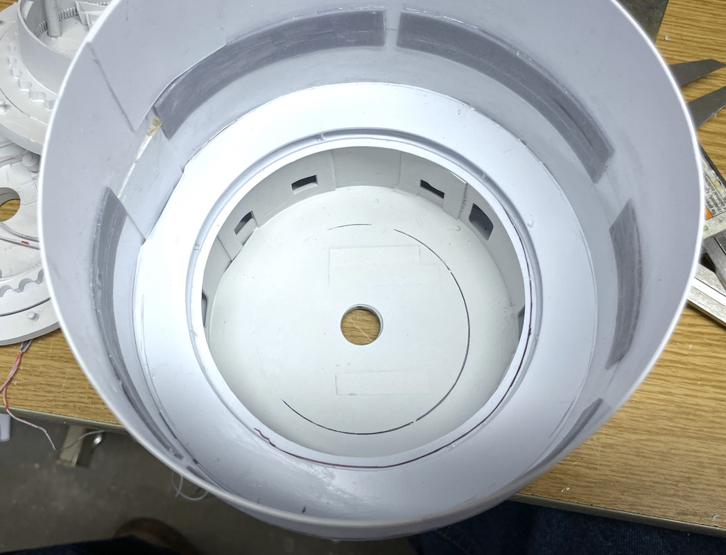
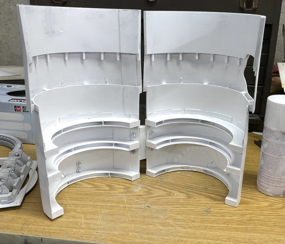
And the interior view;
Notice in the above, I added some cover pieces on the open ends of the annular decks. I didn’t like how ragged they looked AND there was some epoxy filler in some that was very hard to remove. The viewers probably won’t object to this. I also broke loose one of the decks when I was applying pressure on the structure during the drilling/screwing operation. I was worried about the structural integrity of these joints and my fears were well-founded.
Here’s the outside of the just primed shells. I couldn’t really see the piant laying on. I was wearing my chemical respirator AND safety googles besides my normal glasses, and couldn’t see much of what was going on. Ergo, I got some runs. White is a tough color to spray for that reason. I smeared the paint with my nitrile-gloved finger to reduce its height and will do some post-priming finishing to restore the surface before finish coats.
And the insides,
And I even started masking the rotating decks. I got the powder flat and the first projectile flat masked to paint the deck portion. The powder flat gets a linoleum brown and the projectile flats gets burnt iron since they are bare steel. The inner portion might be linoleum or painted steel, but the rotating parts are bare steel with heavy coatings of grease so the projectiles can be easily slid to the hoists.
Have a great weekend and Happy Halloween for all those readers who live in places where this is celebrated. In Louisville, Halloween is a big deal, in many casse more so than Christmas. There’s a street, Hillcrest, where the decorations are so over the top, that 1,000s of people visit there. When the houses are sold, the decorations are conveyed with the property and the new owners are honor-bound to keep it going.
4 Likes
Remember when I said that the fun part was starting now that I’m painting and assembling? Well… perhaps I spoke too soon “Premature adulation”. Before I get into this, I did a punchlist item: I installed the periscope mount that spans the open area of the gun house. I tacked it in place with solvent cement and then pulled out the big guns… J-B Weld 50-Minute Epoxy. This little strip was part of the scrap that I removed when cutting open the gun house roof, and is essential to hold the kit exterior periscope part and my detailed interior periscope part. I was champing at the bitt to take the gun house out and paint the inside white using the Rustoleum since I was effectively out of Tamiya primer (again!). Then I realized that this important piece needed to be in place before any painting.
I finished masking the projectile flats and then did another punch list item: I had to make the penetrations into the powder flat to mount the exterior powder scuttle parts and the access hatches to go from the turret proper to the magazine. To make the holes correspond to their interior bulkhead counterparts, I put masking tape over the powder flat walls and traced the openings, then transferred the tape to the outer shells. I scribed a datum line corresponding to the correct height and put the tape down. I had to guesstimate where the holes would go since the shell is in the open position. Furthermore; while I’m modeling turret #1, the scuttle placement seems to be of turret #2 or 3. There are not port and starboard access points on turret#1 since this is truncated due to interference of the ship’s framing.
Additional complication stems from the junction bracket holding the two shells apart which DOES NOT exist on the real ship.
Here’s the tape applied to the shells.

The radius for the door opening’s round corners is just about 1/8" and I have a nice 1/4" drill with a point for drilling plastics. A plastic bit has a sharper included angle than a normal twist drill. I used a small drill to find the center that would give the right curvature, and then drilled the four corners.
After opening up the corners, I removed the rest of the stock with the carbide router.
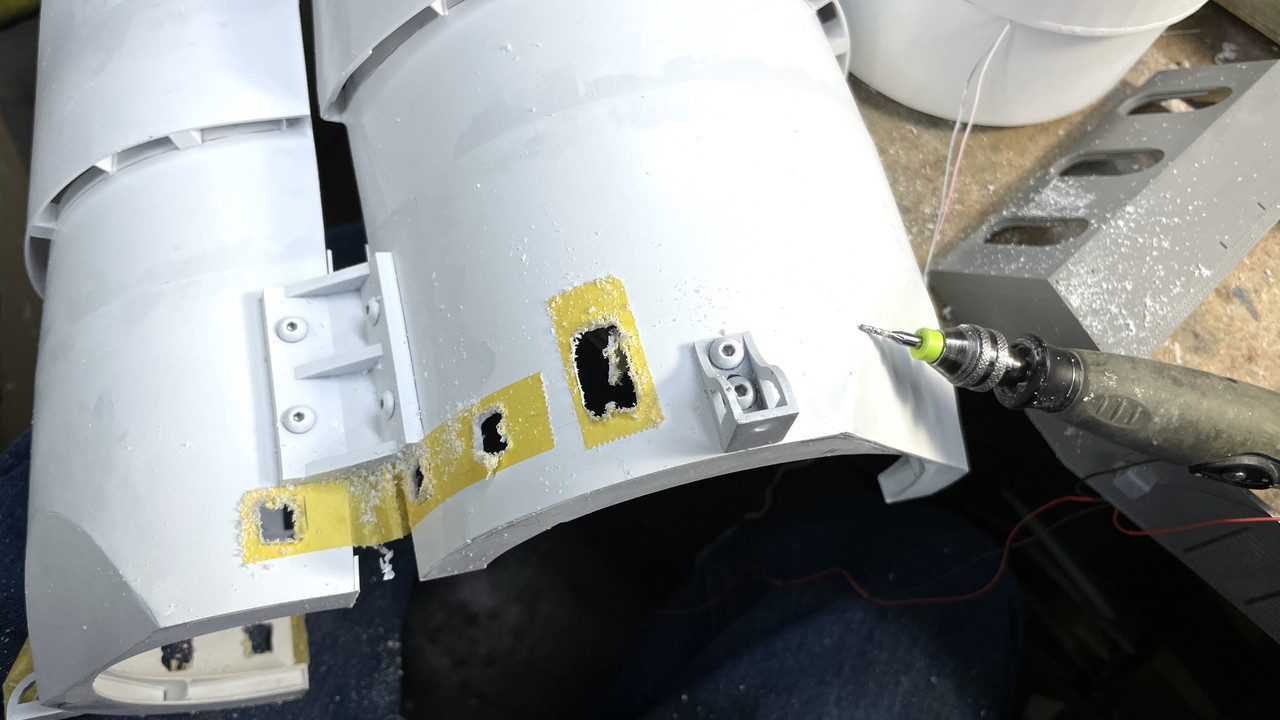
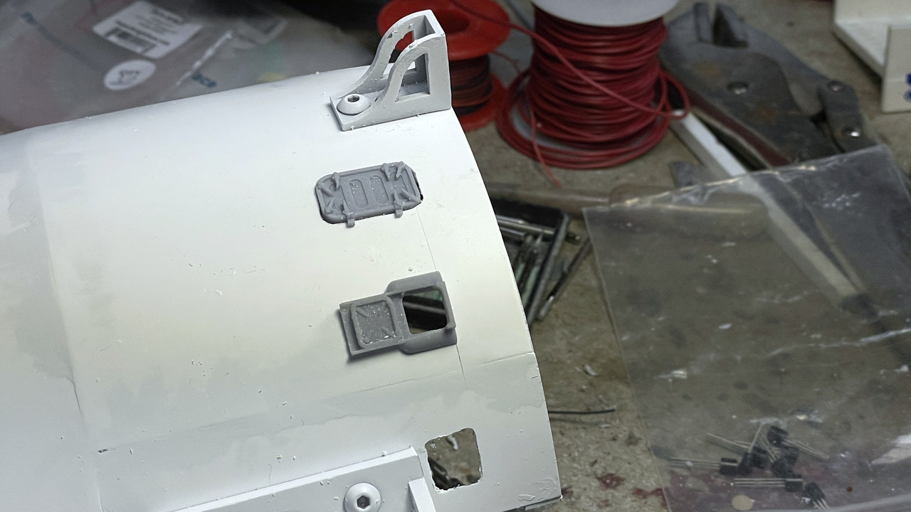
I used the actual 3D printed parts to shape the final openings and did so with the power micro-sander and some jewelers files. Could use a smidgeon of filler…Notice how the junction bracket inpinges on the place where the scuttle door.
Then the nightmare ensued… When I was doing the primer painting outside last week, I ran out of the Tamiya primer and turned to Rust-oleum white 2 in 1 primer. This was a TERRIBLE MISTAKE!!!
While I’m sure that this paint does have good adhesion to plastic which is noted on the label, it appears to have ABSOLUTELY NO ADHESION over Tamiya white primer. I airbrushed the linoleum brown (which looked good, I might add) and then pulled the tape off and with it came 50% of the Rust-oleum with it. Disaster!
I went aroud with more tape and pulled off as much of it as I could. After this I repainted it with a mix of Tamiya Flat and Gloss White.
I needed to remask this whole deal covering up the newly painted linoleum. I used the wide Tamiya tape trimmed to the perimeter and then cut a custom mask for the buik.
I resprayed the white and then pulled the tape… which was the last thing I did before dinner. This is what happened: Rust-oleum nightmare Part Deux!

I’m not going to remask, I’m just going to brush paint the linoleum brown. What I’m fearing is what’s going to happen when I pull the tape off the projectile flats… ugh! I still have to mask and paint the decking on the electric and pan decks, and they too have been sprayed with the Rust-oleum. So instead of breezing through this part of the project, I’m in crisis mode with a lot of redos. Really a big, unexpected, pain in the butt!
The model will get built… it’s just not a straight line.
5 Likes
Very strange, I never knew that the only thing Tamiya primer can’t handle is another primer. Some fiendish repellent in their recipe to deter competitors perhaps? No doubt I’ve skipped a cog somewhere so pls remind me what’s the purpose of primer-over-primer?
It almost looks like Grand Scale Chipping, perfect if this was going to be a rusting derelict. ![]()
1 Like